1998 OPEL FRONTERA check engine
[x] Cancel search: check enginePage 1081 of 6000
6D1–2
ENGINE ELECTRICAL
Battery
General Description
There are six battery fluid caps on top of the battery.
These are covered by a paper label.
The battery is completely sealed except for the six small
vent holes on the side. These vent holes permit the
escape of small amounts of gas generated by the battery.
This type of battery has the following advantages over
conventional batteries:
1. There is no need to add water during the entire
service life of the battery.
2. The battery protects itself against overcharging.
The battery will refuse to accept an extensive charge.
(A conventional battery will accept an excessive
charge, resulting in gassing and loss of battery fluid.)
3. The battery is much less vulnerable to self discharge
than a conventional type battery.
Diagnosis
1. Visual Inspection
Inspect the battery for obvious physical damage, such as
a cracked or broken case, which would permit electrolyte
loss.
Replace the battery if obvious physical damage is
discovered during inspection.
Check for any other physical damage and correct it as
necessary.
2. Hydrometer Check
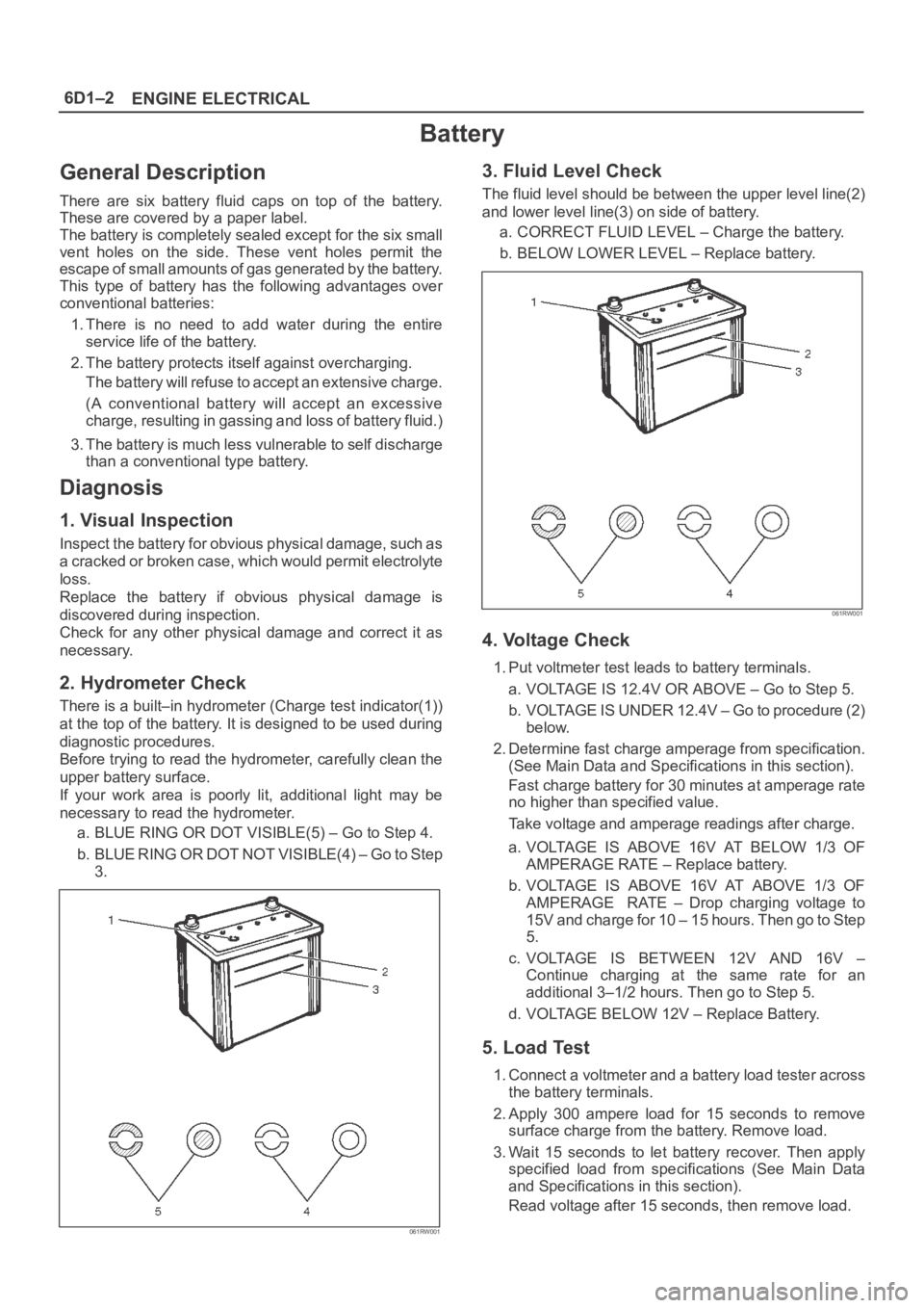
There is a built–in hydrometer (Charge test indicator(1))
at the top of the battery. It is designed to be used during
diagnostic procedures.
Before trying to read the hydrometer, carefully clean the
upper battery surface.
If your work area is poorly lit, additional light may be
necessary to read the hydrometer.
a. BLUE RING OR DOT VISIBLE(5) – Go to Step 4.
b . B L U E R I N G O R D O T N O T V I S I B L E ( 4 ) – G o t o S t e p
3.
061RW001
3. Fluid Level Check
The fluid level should be between the upper level line(2)
and lower level line(3) on side of battery.
a. CORRECT FLUID LEVEL – Charge the battery.
b. BELOW LOWER LEVEL – Replace battery.
061RW001
4. Voltage Check
1. Put voltmeter test leads to battery terminals.
a. VOLTAGE IS 12.4V OR ABOVE – Go to Step 5.
b. VOLTAGE IS UNDER 12.4V – Go to procedure (2)
below.
2. Determine fast charge amperage from specification.
(See Main Data and Specifications in this section).
Fast charge battery for 30 minutes at amperage rate
no higher than specified value.
Take voltage and amperage readings after charge.
a. VOLTAGE IS ABOVE 16V AT BELOW 1/3 OF
AMPERAGE RATE – Replace battery.
b. VOLTAGE IS ABOVE 16V AT ABOVE 1/3 OF
AMPERAGE RATE – Drop charging voltage to
15V and charge for 10 – 15 hours. Then go to Step
5.
c. VOLTAGE IS BETWEEN 12V AND 16V –
Continue charging at the same rate for an
additional 3–1/2 hours. Then go to Step 5.
d. VOLTAGE BELOW 12V – Replace Battery.
5. Load Test
1. Connect a voltmeter and a battery load tester across
the battery terminals.
2. Apply 300 ampere load for 15 seconds to remove
surface charge from the battery. Remove load.
3. Wait 15 seconds to let battery recover. Then apply
specified load from specifications (See Main Data
and Specifications in this section).
Read voltage after 15 seconds, then remove load.
Page 1089 of 6000
6D2–4
IGNITION SYSTEM
Spark Plug
Removal
1. Remove spark plugs.
Inspection and Repair
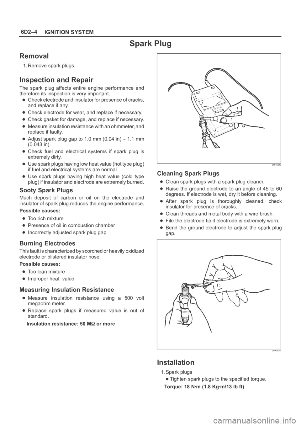
The spark plug affects entire engine performance and
therefore its inspection is very important.
Check electrode and insulator for presence of cracks,
and replace if any.
Check electrode for wear, and replace if necessary.
Check gasket for damage, and replace if necessary.
Measure insulation resistance with an ohmmeter, and
replace if faulty.
Adjust spark plug gap to 1.0 mm (0.04 in) 1.1 mm
(0.043 in).
Check fuel and electrical systems if spark plug is
extremely dirty.
Use spark plugs having low heat value (hot type plug)
if fuel and electrical systems are normal.
Use spark plugs having high heat value (cold type
plug) if insulator and electrode are extremely burned.
Sooty Spark Plugs
Much deposit of carbon or oil on the electrode and
insulator of spark plug reduces the engine performance.
Possible causes:
Too rich mixture
Presence of oil in combustion chamber
Incorrectly adjusted spark plug gap
Burning Electrodes
This fault is characterized by scorched or heavily oxidized
electrode or blistered insulator nose.
Possible causes:
Too lean mixture
Improper heat value
Measuring Insulation Resistance
Measure insulation resistance using a 500 volt
megaohm meter.
Replace spark plugs if measured value is out of
standard.
Insulation resistance: 50 M
or more
011RS010
Cleaning Spark Plugs
Clean spark plugs with a spark plug cleaner.
Raise the ground electrode to an angle of 45 to 60
degrees. If electrode is wet, dry it before cleaning.
After spark plug is thoroughly cleaned, check
insulator for presence of cracks.
Clean threads and metal body with a wire brush.
File the electrode tip if electrode is extremely worn.
Bend the ground electrode to adjust the spark plug
gap.
011RS011
Installation
1. Spark plugs
Tighten spark plugs to the specified torque.
Torque: 18 Nꞏm (1.8 Kgꞏm/13 lb ft)
Page 1109 of 6000
6D3–18STARTING AND CHARGING SYSTEM
Charging System
General Description
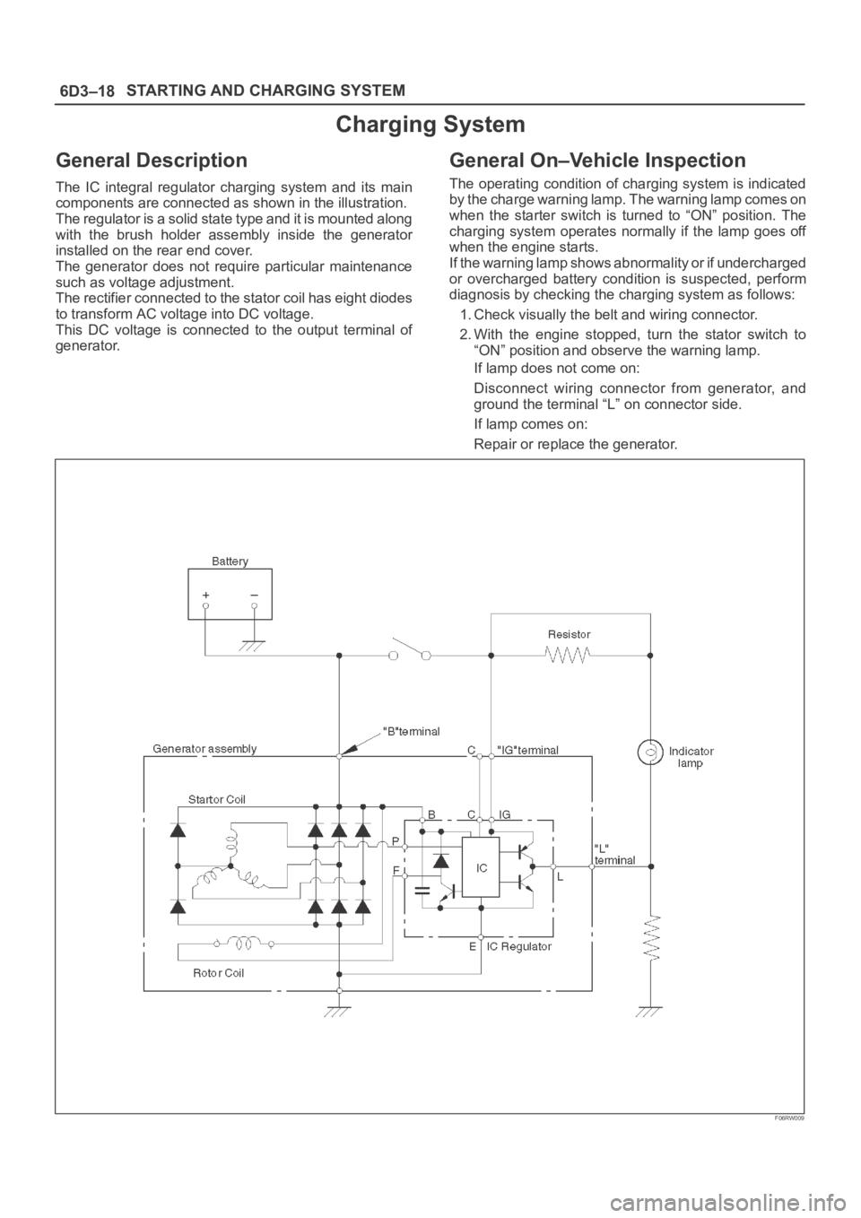
The IC integral regulator charging system and its main
components are connected as shown in the illustration.
The regulator is a solid state type and it is mounted along
with the brush holder assembly inside the generator
installed on the rear end cover.
The generator does not require particular maintenance
such as voltage adjustment.
The rectifier connected to the stator coil has eight diodes
to transform AC voltage into DC voltage.
This DC voltage is connected to the output terminal of
generator.
General On–Vehicle Inspection
The operating condition of charging system is indicated
by the charge warning lamp. The warning lamp comes on
when the starter switch is turned to “ON” position. The
charging system operates normally if the lamp goes off
when the engine starts.
If the warning lamp shows abnormality or if undercharged
or overcharged battery condition is suspected, perform
diagnosis by checking the charging system as follows:
1. Check visually the belt and wiring connector.
2. With the engine stopped, turn the stator switch to
“ON” position and observe the warning lamp.
If lamp does not come on:
Disconnect wiring connector from generator, and
ground the terminal “L” on connector side.
If lamp comes on:
Repair or replace the generator.
F06RW009
Page 1119 of 6000
6E–2
ENGINE DRIVEABILITY AND EMISSIONS
Primary System-Based Diagnostic 6E–50. . . . . . . . .
Primary System-Based Diagnostic 6E–50. . . . . . .
Fuel Control Heated Oxygen Sensor 6E–50. . . . .
HO2S Heater 6E–50. . . . . . . . . . . . . . . . . . . . . . . . .
Fuel Trim System Monitor Diagnostic
Operation 6E–50. . . . . . . . . . . . . . . . . . . . . . . . . . . . . .
Fuel Trim System Monitor Diagnostic
Operation 6E–50. . . . . . . . . . . . . . . . . . . . . . . . . . . .
Fuel Trim Cell Diagnostic Weights 6E–50. . . . . . .
On-Board Diagnostic (OBD) System Check 6E–51.
A/C Clutch Control Circuit Diagnosis 6E–54. . . . . . .
Electronic Ignition System Diagnosis 6E–60. . . . . . .
Fuel Metering System Check 6E–60. . . . . . . . . . . . .
Idle Air Control (IAC) Valve 6E–60. . . . . . . . . . . . . . .
Fuel System Pressure Test 6E–60. . . . . . . . . . . . . . .
Fuel Injector Coil Test Procedure and Fuel
Injector Balance Test Procedure 6E–60. . . . . . . . . .
Knock Sensor Diagnosis 6E–65. . . . . . . . . . . . . . . . .
Powertrain Control Module (PCM) Diagnosis 6E–65
Multiple PCM Information Sensor DTCS Set 6E–65
Exhaust Gas Recirculation (EGR) Diagnosis
(For except EXPORT and
SOUTH AFRICA) 6E–68. . . . . . . . . . . . . . . . . . . . . . .
Engine Tech 2 Data Definitions and Ranges 6E–68
Typical Scan Data Values 6E–70. . . . . . . . . . . . . . . .
No Malfunction Indicator Lamp (MIL) 6E–74. . . . . . .
Malfunction Indicator Lamp (MIL) “ON”
Steady 6E–77. . . . . . . . . . . . . . . . . . . . . . . . . . . . . . . .
Engine Cranks But Will Not Run 6E–79. . . . . . . . . . .
Fuel System Electrical Test 6E–85. . . . . . . . . . . . . . .
Fuel System Diagnosis 6E–88. . . . . . . . . . . . . . . . . . .
Idle Air Control (IAC) System Check 6E–93. . . . . . .
Knock Sensor (KS) System Check
(Engine Knock, Poor Performance, or Poor
Economy) 6E–95. . . . . . . . . . . . . . . . . . . . . . . . . . . . .
Exhaust Gas Recirculation (EGR) System
Check 6E–97. . . . . . . . . . . . . . . . . . . . . . . . . . . . . . . . .
Manifold Absolute Pressure (MAP) Output
Check 6E–99. . . . . . . . . . . . . . . . . . . . . . . . . . . . . . . . .
PCM Diagnostic Trouble Codes 6E–101. . . . . . . . . . .
Diagnostic Trouble Code (DTC) P0101
MAF System Performance 6E–104. . . . . . . . . . . . . . .
Diagnostic Trouble Code (DTC) P0102
MAF Sensor Circuit Low Frequency 6E–107. . . . . .
Diagnostic Trouble Code (DTC) P0103
MAF Sensor Circuit High Frequency 6E–110. . . . . .
Diagnostic Trouble Code (DTC) P0107
MAP Sensor Circuit Low Voltage 6E–112. . . . . . . . . .
Diagnostic Trouble Code (DTC) P0108
MAP Sensor Circuit High Voltage 6E–115. . . . . . . . .
Diagnostic Trouble Code (DTC) P0112
IAT Sensor Circuit Low Voltage 6E–118. . . . . . . . . . .
Diagnostic Trouble Code (DTC) P0113
IAT Sensor Circuit High Voltage 6E–121. . . . . . . . . . Diagnostic Trouble Code (DTC) P0117
ECT Sensor Circuit Low Voltage 6E–124. . . . . . . . . .
Diagnostic Trouble Code (DTC) P0118
ECT Sensor Circuit High Voltage 6E–127. . . . . . . . .
Diagnostic Trouble Code (DTC) P0121
TP System Performance 6E–130. . . . . . . . . . . . . . . . .
Diagnostic Trouble Code (DTC) P0122
TP Sensor Circuit Low Voltage 6E–133. . . . . . . . . . .
Diagnostic Trouble Code (DTC) P0123
TP Sensor Circuit High Voltage 6E–136. . . . . . . . . .
Diagnostic Trouble Code (DTC) P0131
HO2S Circuit Low Voltage Bank 1
Sensor 1 6E–139. . . . . . . . . . . . . . . . . . . . . . . . . . . . . . .
Diagnostic Trouble Code (DTC) P0132
HO2S Circuit High Voltage Bank 1
Sensor 1 6E–142. . . . . . . . . . . . . . . . . . . . . . . . . . . . . . .
Diagnostic Trouble Code (DTC) P0134
HO2S Circuit Insufficient Activity Bank 1
Sensor 1 6E–145. . . . . . . . . . . . . . . . . . . . . . . . . . . . . .
Diagnostic Trouble Code (DTC) P0151
HO2S Circuit Low Voltage Bank 2
Sensor 1 6E–148. . . . . . . . . . . . . . . . . . . . . . . . . . . . . . .
Diagnostic Trouble Code (DTC) P0152
HO2S Circuit HIGH Voltage Bank 2
Sensor 1 6E–151. . . . . . . . . . . . . . . . . . . . . . . . . . . . . . .
Diagnostic Trouble Code (DTC) P0171
Fuel Trim System Lean Bank 1 6E–154. . . . . . . . . . .
Diagnostic Trouble Code (DTC) P0172
Fuel Trim System Rich Bank 1 6E–158. . . . . . . . . . .
Diagnostic Trouble Code (DTC) P0174
Fuel Trim System Lean Bank 2 6E–162. . . . . . . . . . .
Diagnostic Trouble Code (DTC) P0175
Fuel Trim System Rich Bank 2 6E–166. . . . . . . . . . .
Diagnostic Trouble Code (DTC) P0201
Injector 1 Control Circuit 6E–170. . . . . . . . . . . . . . . . .
Diagnostic Trouble Code (DTC) P0202
Injector 2 Control Circuit 6E–173. . . . . . . . . . . . . . . . .
Diagnostic Trouble Code (DTC) P0203
Injector 3 Control Circuit 6E–176. . . . . . . . . . . . . . . . .
Diagnostic Trouble Code (DTC) P0204
Injector 4 Control Circuit 6E–179. . . . . . . . . . . . . . . . .
Diagnostic Trouble Code (DTC) P0205
Injector 5 Control Circuit 6E–182. . . . . . . . . . . . . . . . .
Diagnostic Trouble Code (DTC) P0206
Injector 6 Control Circuit 6E–185. . . . . . . . . . . . . . . . .
Diagnostic Trouble Code (DTC) P0325
KS Module Circuit 6E–188. . . . . . . . . . . . . . . . . . . . . .
Diagnostic Trouble Code (DTC) P0327
KS Sensor Circuit 6E–190. . . . . . . . . . . . . . . . . . . . . . .
Diagnostic Trouble Code (DTC) P0336
58X Reference Signal Circuit 6E–193. . . . . . . . . . . . .
Diagnostic Trouble Code (DTC) P0337
CKP Sensor Circuit Low Frequency 6E–195. . . . . . .
Diagnostic Trouble Code (DTC) P0341
CMP Sensor Circuit Performance 6E–198. . . . . . . . .
Diagnostic Trouble Code (DTC) P0342
CMP Sensor Circuit Low 6E–202. . . . . . . . . . . . . . . . .
Page 1134 of 6000
6E–17 ENGINE DRIVEABILITY AND EMISSIONS
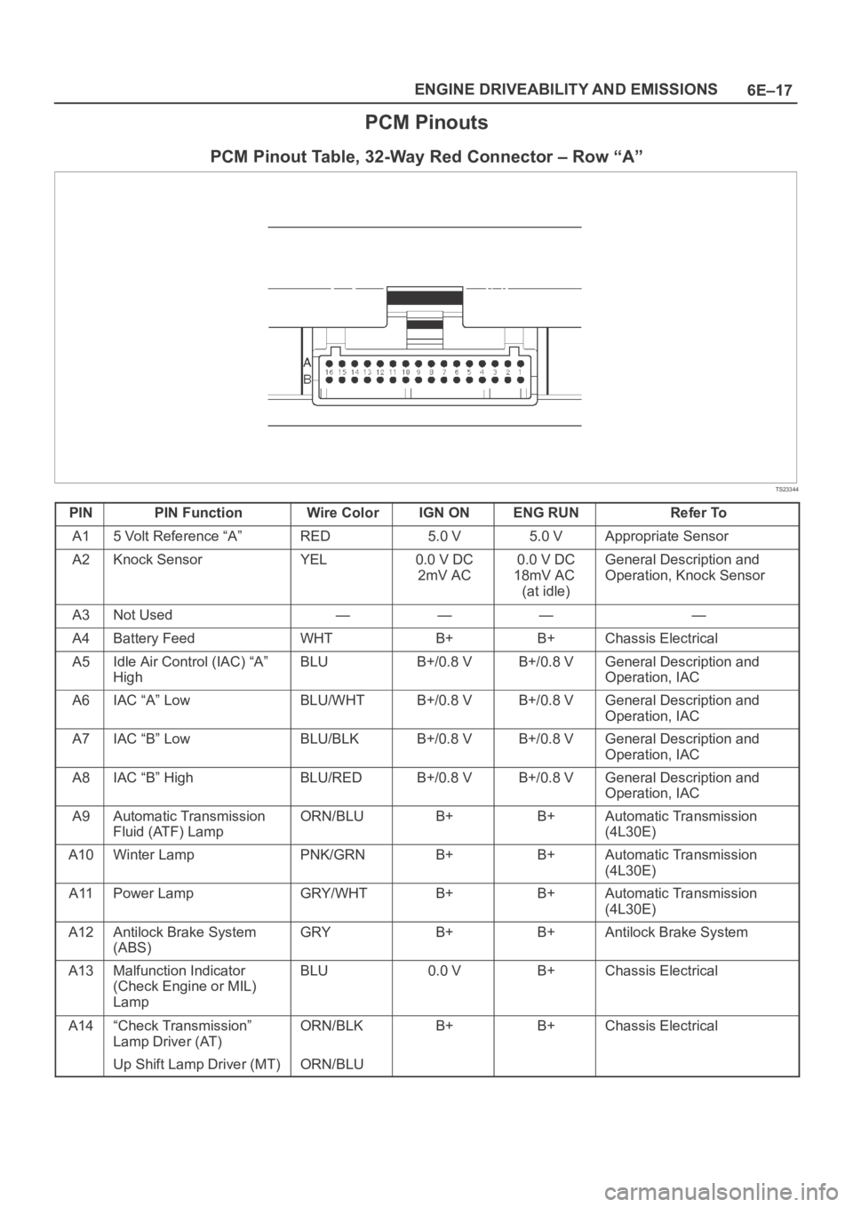
PCM Pinouts
PCM Pinout Table, 32-Way Red Connector – Row “A”
TS23344
PINPIN FunctionWire ColorIGN ONENG RUNRefer To
A15 Volt Reference “A”RED5.0 V5.0 VAppropriate Sensor
A2Knock SensorYEL0.0 V DC
2mV AC0.0 V DC
18mV AC
(at idle)General Description and
Operation, Knock Sensor
A3Not Used————
A4Battery FeedWHTB+B+Chassis Electrical
A5Idle Air Control (IAC) “A”
HighBLUB+/0.8 VB+/0.8 VGeneral Description and
Operation, IAC
A6IAC “A” LowBLU/WHTB+/0.8 VB+/0.8 VGeneral Description and
Operation, IAC
A7IAC “B” LowBLU/BLKB+/0.8 VB+/0.8 VGeneral Description and
Operation, IAC
A8IAC “B” HighBLU/REDB+/0.8 VB+/0.8 VGeneral Description and
Operation, IAC
A9Automatic Transmission
Fluid (ATF) LampORN/BLUB+B+Automatic Transmission
(4L30E)
A10Winter LampPNK/GRNB+B+Automatic Transmission
(4L30E)
A11Power LampGRY/WHTB+B+Automatic Transmission
(4L30E)
A12Antilock Brake System
(ABS)GRYB+B+Antilock Brake System
A13Malfunction Indicator
(Check Engine or MIL)
LampBLU0.0 VB+Chassis Electrical
A14“Check Transmission”
Lamp Driver (AT)ORN/BLKB+B+Chassis Electrical
Up Shift Lamp Driver (MT)ORN/BLU
Page 1146 of 6000
6E–29 ENGINE DRIVEABILITY AND EMISSIONS
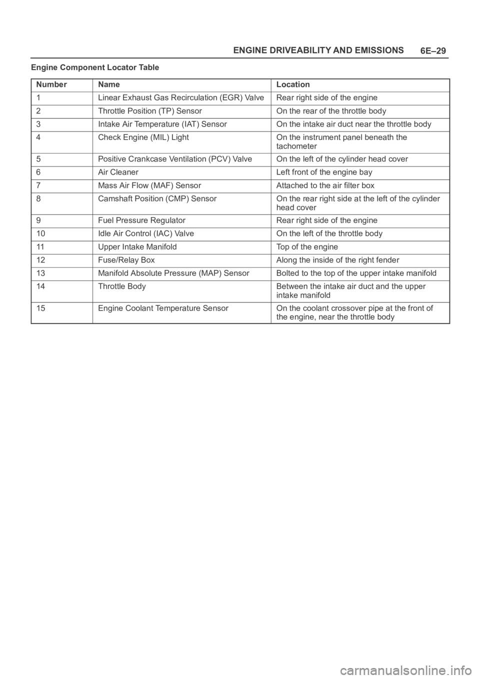
Engine Component Locator Table
Number
NameLocation
1Linear Exhaust Gas Recirculation (EGR) ValveRear right side of the engine
2Throttle Position (TP) SensorOn the rear of the throttle body
3Intake Air Temperature (IAT) SensorOn the intake air duct near the throttle body
4Check Engine (MIL) LightOn the instrument panel beneath the
tachometer
5Positive Crankcase Ventilation (PCV) ValveOn the left of the cylinder head cover
6Air CleanerLeft front of the engine bay
7Mass Air Flow (MAF) SensorAttached to the air filter box
8Camshaft Position (CMP) SensorOn the rear right side at the left of the cylinder
head cover
9Fuel Pressure RegulatorRear right side of the engine
10Idle Air Control (IAC) ValveOn the left of the throttle body
11Upper Intake ManifoldTop of the engine
12Fuse/Relay BoxAlong the inside of the right fender
13Manifold Absolute Pressure (MAP) SensorBolted to the top of the upper intake manifold
14Throttle BodyBetween the intake air duct and the upper
intake manifold
15Engine Coolant Temperature SensorOn the coolant crossover pipe at the front of
the engine, near the throttle body
Page 1148 of 6000
6E–31 ENGINE DRIVEABILITY AND EMISSIONS
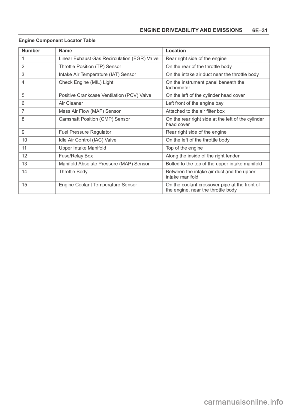
Engine Component Locator Table
Number
NameLocation
1Linear Exhaust Gas Recirculation (EGR) ValveRear right side of the engine
2Throttle Position (TP) SensorOn the rear of the throttle body
3Intake Air Temperature (IAT) SensorOn the intake air duct near the throttle body
4Check Engine (MIL) LightOn the instrument panel beneath the
tachometer
5Positive Crankcase Ventilation (PCV) ValveOn the left of the cylinder head cover
6Air CleanerLeft front of the engine bay
7Mass Air Flow (MAF) SensorAttached to the air filter box
8Camshaft Position (CMP) SensorOn the rear right side at the left of the cylinder
head cover
9Fuel Pressure RegulatorRear right side of the engine
10Idle Air Control (IAC) ValveOn the left of the throttle body
11Upper Intake ManifoldTop of the engine
12Fuse/Relay BoxAlong the inside of the right fender
13Manifold Absolute Pressure (MAP) SensorBolted to the top of the upper intake manifold
14Throttle BodyBetween the intake air duct and the upper
intake manifold
15Engine Coolant Temperature SensorOn the coolant crossover pipe at the front of
the engine, near the throttle body
Page 1154 of 6000
6E–37 ENGINE DRIVEABILITY AND EMISSIONS
Diagnosis
Strategy-Based Diagnostics
Strategy-Based Diagnostics
The strategy-based diagnostic is a uniform approach to
repair all Electrical/Electronic (E/E) systems. The
diagnostic flow can always be used to resolve an E/E
system problem and is a starting point when repairs are
necessary. The following steps will instruct the technician
how to proceed with a diagnosis:
1. Verify the customer complaint.
To verify the customer complaint, the technician
should know the normal operation of the system.
2. Perform preliminary checks.
Conduct a thorough visual inspection.
Review the service history.
Detect unusual sounds or odors.
Gather diagnostic trouble code information to
achieve an effective repair.
3. Check bulletins and other service information.
This includes videos, newsletters, etc.
4. Refer to service information (manual) system
check(s).
“System checks” contain information on a system
that may not be supported by one or more DTCs.
System checks verify proper operation of the
system. This will lead the technician in an
organized approach to diagnostics.
5. Refer to service diagnostics.
DTC Stored
Follow the designated DTC chart exactly to make an
effective repair.
No DTC
Select the symptom from the symptom tables. Follow the
diagnostic paths or suggestions to complete the repair.
You may refer to the applicable component/system check
in the system checks.
No Matching Symptom
1. Analyze the complaint.
2. Develop a plan for diagnostics.
3. Utilize the wiring diagrams and the theory of
operation.
Call technical assistance for similar cases where repair
history may be available. Combine technician knowledge
with efficient use of the available service information.
Intermittents
Conditions that are not always present are called
intermittents. To resolve intermittents, perform the
following steps:
1. Observe history DTCs, DTC modes, and freezeframe
data.
2. Evaluate the symptoms and the conditions described
by the customer.3. Use a check sheet or other method to identify the
circuit or electrical system component.
4. Follow the suggestions for intermittent diagnosis
found in the service documentation.
Most Tech 2s, such as the Tech II and the
5–8840–0285–0 (Fluke model 87 DVOM), have
data-capturing capabilities that can assist in detecting
intermittents.
No Trouble Found
This condition exists when the vehicle is found to operate
normally. The condition described by the customer may
be normal. Verify the customer complaint against another
vehicle that is operating normally. The condition may be
intermittent. Verify the complaint under the conditions
described by the customer before releasing the vehicle.
1. Re-examine the complaint.
When the Complaint cannot be successfully found or
isolated, a re-evaluation is necessary. The complaint
should be re-verified and could be intermittent as
defined in
Intermittents, or could be normal.
2. Repair and verify.
After isolating the cause, the repairs should be made.
Validate for proper operation and verify that the
symptom has been corrected. This may involve road
testing or other methods to verify that the complaint
has been resolved under the following conditions:
Conditions noted by the customer.
If a DTC was diagnosed, verify a repair by
duplicating conditions present when the DTC was
set as noted in the Failure Records or Freeze
Frame data.
Verifying Vehicle Repair
Verification of the vehicle repair will be more
comprehensive for vehicles with OBD system
diagnostics. Following a repair, the technician should
perform the following steps:
IMPORTANT:Follow the steps below when you verify
repairs on OBD systems. Failure to follow these steps
could result in unnecessary repairs.
1. Review and record the Failure Records and the
Freeze Frame data for the DTC which has been
diagnosed (Freeze Frame data will only be stored for
an A or B type diagnostic and only if the MIL(”Check
Engine” lamp) has been requested).
2. Clear the DTC(S).
3. Operate the vehicle within conditions noted in the
Failure Records and Freeze Frame data.
4. Monitor the DTC status information for the specific
DTC which has been diagnosed until the diagnostic
test associated with that DTC runs.