1998 OPEL FRONTERA check engine
[x] Cancel search: check enginePage 2994 of 6000

WIRING SYSTEM 8D–401
STEP OPERATION ITEM TO BE CHECKEDITEM OF
REMARKS
MALFUNCTION
Be sure to lock door
with locking knob.
Activate alarm
device.
All doors are
unlocked.
With key set at unlock
position, check to see
if alarm stops.
All doors are
locked.
Activate alarm
device.
Activate alarm
device.
Only left rear door
is unlocked. Check to see if engine hood,
tailgate and doors are closed and
locked.
Check to see if indicator light
remains lit off.
Check to see if indicator light
flashes.
Check to see if dome light and
courtesy light illuminate.
Check to see if indicator light
changes from flashing to steadily
on.
Check to see if indicator light
turns off in about 10 seconds.
Check to see if alarm operates
(with headlight flashing, and horn
blaring intermittently.)
Check to see if alarm stops.
Check to see if indicator light
turns on.
Check to see if indicator light
goes off after about 10 seconds.
Check to see if alarm does not
operate.
Check to see if indicator light
turns on.
Check to see if indicator light
goes off after about 10 seconds.
Check to see if alarm starts. Turn starter key to “ON” position.
Open windows fully.
Pull out starter key after turning it
back to “OFF” position.
Unlock left front door with locking
knob.
Open left front door. (And get out
of the vehicle.)
Close left front door.
Lock left front door.
Wait about 10 seconds
Unlock left front door with locking
knob.
Insert key into key cylinder of left
front door and turn it in unlock
direction.
Lock left front door.
Wait for about 10 seconds.
Unlock left front door with key.
Lock left front door with key.
Wait for about 10 seconds.
Unlock left rear door with locking
knob.K
A
B
C
D
E
B
C
F
B
C
D 1
2
3
4
5
6
7
8
9
10
11
12
13
14
15
16
Page 2997 of 6000
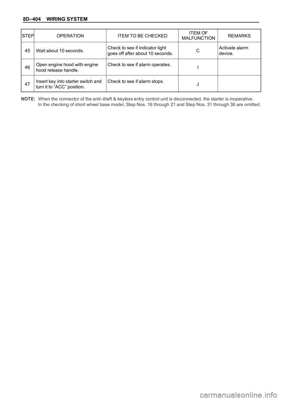
8D–404 WIRING SYSTEM
STEP OPERATION ITEM TO BE CHECKEDITEM OF
REMARKS
MALFUNCTION
Activate alarm
device. Check to see if indicator light
goes off after about 10 seconds.
Check to see if alarm operates.
Check to see if alarm stops. Wait about 10 seconds.
Open engine hood with engine
hood release handle.
Insert key into starter switch and
turn it to “ACC” position.C
I
J 45
46
47
NOTE:When the connector of the anti–theft & keyless entry control unit is disconnected, the starter is inoperative.
In the checking of short wheel base model, Step Nos. 16 through 21 and Step Nos. 31 through 36 are omitted.
Page 2998 of 6000

WIRING SYSTEM 8D–405
TERMINAL
CONNECTIONCHECK
OPERATIONCIRCUIT
NO. ITEM CONDITION
1 FRT door switch–LH, RH ContinuityOpen door Continuity
Close door No continuity
2 RR door switch–LH, RH ContinuityOpen door Continuity
Close door No continuity
3— — – –
4 Door lock key switch–LH, RH Continuity Lock with key Continuity
5 FRT door lock switch–LH, RH Continuity Lock Continuity
6 Tailgate switch ContinuityOpen tailgate Continuity
Close tailgate No continuity
8 Anti–theft horn Voltage – Approx. 12V
10 Battery Voltage – Approx. 12V
11 Door switch ContinuityUnlock with locking knob Continuity
Lock with locking knob No continuity
12 Engine hood switch ContinuityOpen engine hood Continuity
Close engine hood No continuity
13 Detect switch ContinuityUnlock with key Continuity
Lock with key No continuity
14 Door lock key switch Continuity Unlock Continuity
15 FRT door lock switch–LH, RH Continuity Unlock Continuity
16 Tamper switch Continuity – No continuity
17 Ground Continuity – Continuity
18 Starter switch Voltage Starter switch “ACC” Approx. 12V
19 Indicator light Voltage – Approx. 12V
20 Dome light Voltage Dome light “DOOR” position Approx. 12V
21 Anti-theft relay Voltage – Approx. 12V
22 Starter relay VoltageMode switch “P” or “N” Approx. 12V
Clutch pedal depressed Approx. 12V
Check the anti–theft & keyless entry control unit harness side connector B–20 by using a circuit tester.
Page 3186 of 6000
METER AND GAUGE8E–9
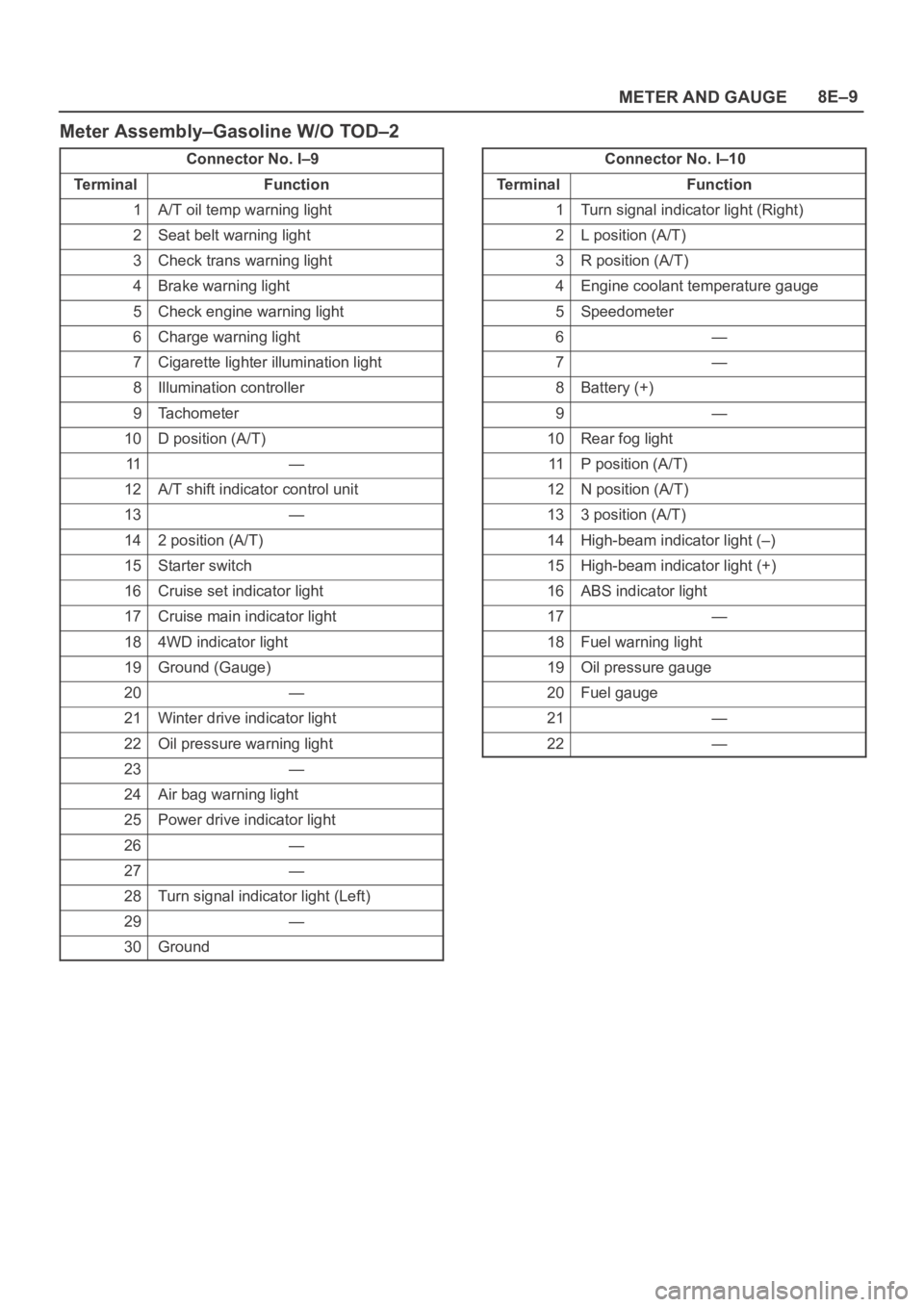
Meter Assembly–Gasoline W/O TOD–2
Connector No. I–9
Te r m i n a lFunction
1A/T oil temp warning light
2Seat belt warning light
3Check trans warning light
4Brake warning light
5Check engine warning light
6Charge warning light
7Cigarette lighter illumination light
8Illumination controller
9Tachometer
10D position (A/T)
11—
12A/T shift indicator control unit
13—
142 position (A/T)
15Starter switch
16Cruise set indicator light
17Cruise main indicator light
184WD indicator light
19Ground (Gauge)
20—
21Winter drive indicator light
22Oil pressure warning light
23—
24Air bag warning light
25Power drive indicator light
26—
27—
28Turn signal indicator light (Left)
29—
30Ground
Connector No. I–10
Te r m i n a lFunction
1Turn signal indicator light (Right)
2L position (A/T)
3R position (A/T)
4Engine coolant temperature gauge
5Speedometer
6—
7—
8Battery (+)
9—
10Rear fog light
11P position (A/T)
12N position (A/T)
133 position (A/T)
14High-beam indicator light (–)
15High-beam indicator light (+)
16ABS indicator light
17—
18Fuel warning light
19Oil pressure gauge
20Fuel gauge
21—
22—
Page 3188 of 6000
METER AND GAUGE8E–11
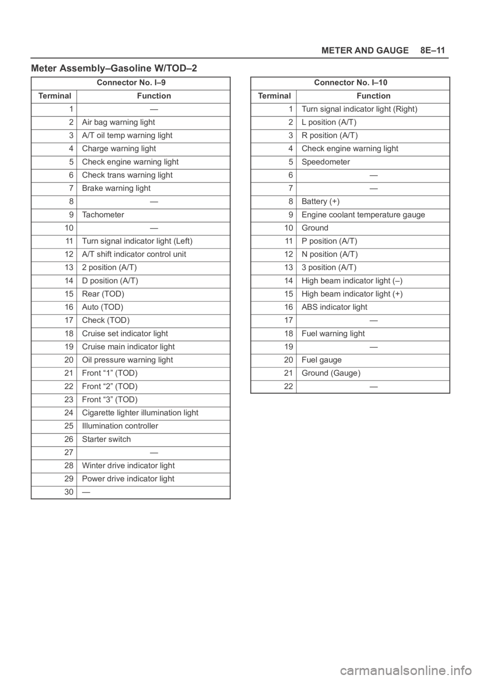
Meter Assembly–Gasoline W/TOD–2
Connector No. I–9
Te r m i n a lFunction
1—
2Air bag warning light
3A/T oil temp warning light
4Charge warning light
5Check engine warning light
6Check trans warning light
7Brake warning light
8—
9Tachometer
10—
11Turn signal indicator light (Left)
12A/T shift indicator control unit
132 position (A/T)
14D position (A/T)
15Rear (TOD)
16Auto (TOD)
17Check (TOD)
18Cruise set indicator light
19Cruise main indicator light
20Oil pressure warning light
21Front “1” (TOD)
22Front “2” (TOD)
23Front “3” (TOD)
24Cigarette lighter illumination light
25Illumination controller
26Starter switch
27—
28Winter drive indicator light
29Power drive indicator light
30—
Connector No. I–10
Te r m i n a lFunction
1Turn signal indicator light (Right)
2L position (A/T)
3R position (A/T)
4Check engine warning light
5Speedometer
6—
7—
8Battery (+)
9Engine coolant temperature gauge
10Ground
11P position (A/T)
12N position (A/T)
133 position (A/T)
14High beam indicator light (–)
15High beam indicator light (+)
16ABS indicator light
17—
18Fuel warning light
19—
20Fuel gauge
21Ground (Gauge)
22—
Page 3196 of 6000
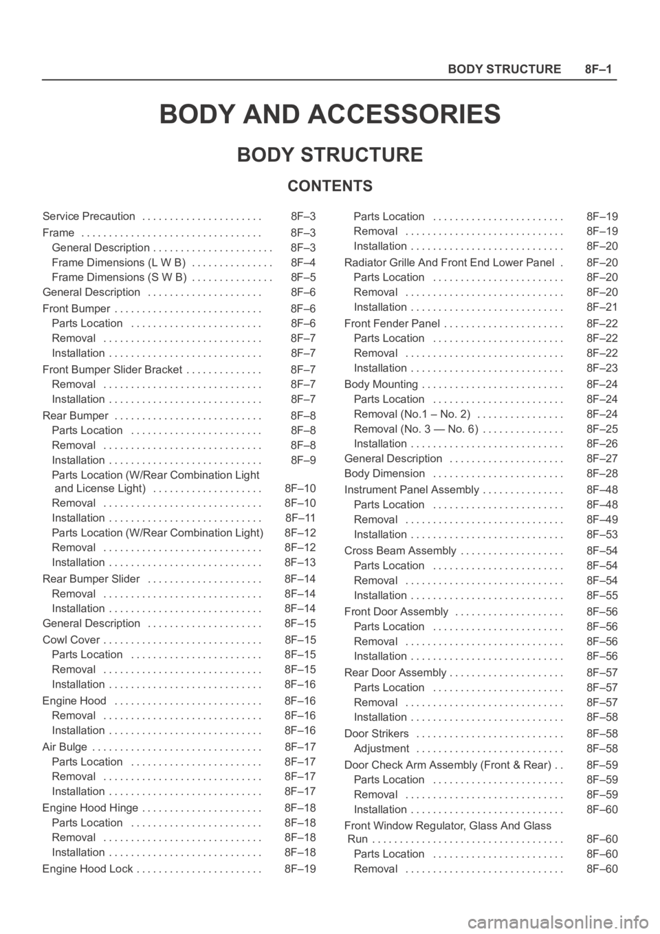
8F–1 BODY STRUCTURE
BODY AND ACCESSORIES
BODY STRUCTURE
CONTENTS
Service Precaution 8F–3. . . . . . . . . . . . . . . . . . . . . .
Frame 8F–3. . . . . . . . . . . . . . . . . . . . . . . . . . . . . . . . .
General Description 8F–3. . . . . . . . . . . . . . . . . . . . . .
Frame Dimensions (L W B) 8F–4. . . . . . . . . . . . . . .
Frame Dimensions (S W B) 8F–5. . . . . . . . . . . . . . .
General Description 8F–6. . . . . . . . . . . . . . . . . . . . .
Front Bumper 8F–6. . . . . . . . . . . . . . . . . . . . . . . . . . .
Parts Location 8F–6. . . . . . . . . . . . . . . . . . . . . . . .
Removal 8F–7. . . . . . . . . . . . . . . . . . . . . . . . . . . . .
Installation 8F–7. . . . . . . . . . . . . . . . . . . . . . . . . . . .
Front Bumper Slider Bracket 8F–7. . . . . . . . . . . . . .
Removal 8F–7. . . . . . . . . . . . . . . . . . . . . . . . . . . . .
Installation 8F–7. . . . . . . . . . . . . . . . . . . . . . . . . . . .
Rear Bumper 8F–8. . . . . . . . . . . . . . . . . . . . . . . . . . .
Parts Location 8F–8. . . . . . . . . . . . . . . . . . . . . . . .
Removal 8F–8. . . . . . . . . . . . . . . . . . . . . . . . . . . . .
Installation 8F–9. . . . . . . . . . . . . . . . . . . . . . . . . . . .
Parts Location (W/Rear Combination Light
and License Light) 8F–10. . . . . . . . . . . . . . . . . . . .
Removal 8F–10. . . . . . . . . . . . . . . . . . . . . . . . . . . . .
Installation 8F–11. . . . . . . . . . . . . . . . . . . . . . . . . . . .
Parts Location (W/Rear Combination Light) 8F–12
Removal 8F–12. . . . . . . . . . . . . . . . . . . . . . . . . . . . .
Installation 8F–13. . . . . . . . . . . . . . . . . . . . . . . . . . . .
Rear Bumper Slider 8F–14. . . . . . . . . . . . . . . . . . . . .
Removal 8F–14. . . . . . . . . . . . . . . . . . . . . . . . . . . . .
Installation 8F–14. . . . . . . . . . . . . . . . . . . . . . . . . . . .
General Description 8F–15. . . . . . . . . . . . . . . . . . . . .
Cowl Cover 8F–15. . . . . . . . . . . . . . . . . . . . . . . . . . . . .
Parts Location 8F–15. . . . . . . . . . . . . . . . . . . . . . . .
Removal 8F–15. . . . . . . . . . . . . . . . . . . . . . . . . . . . .
Installation 8F–16. . . . . . . . . . . . . . . . . . . . . . . . . . . .
Engine Hood 8F–16. . . . . . . . . . . . . . . . . . . . . . . . . . .
Removal 8F–16. . . . . . . . . . . . . . . . . . . . . . . . . . . . .
Installation 8F–16. . . . . . . . . . . . . . . . . . . . . . . . . . . .
Air Bulge 8F–17. . . . . . . . . . . . . . . . . . . . . . . . . . . . . . .
Parts Location 8F–17. . . . . . . . . . . . . . . . . . . . . . . .
Removal 8F–17. . . . . . . . . . . . . . . . . . . . . . . . . . . . .
Installation 8F–17. . . . . . . . . . . . . . . . . . . . . . . . . . . .
Engine Hood Hinge 8F–18. . . . . . . . . . . . . . . . . . . . . .
Parts Location 8F–18. . . . . . . . . . . . . . . . . . . . . . . .
Removal 8F–18. . . . . . . . . . . . . . . . . . . . . . . . . . . . .
Installation 8F–18. . . . . . . . . . . . . . . . . . . . . . . . . . . .
Engine Hood Lock 8F–19. . . . . . . . . . . . . . . . . . . . . . . Parts Location 8F–19. . . . . . . . . . . . . . . . . . . . . . . .
Removal 8F–19. . . . . . . . . . . . . . . . . . . . . . . . . . . . .
Installation 8F–20. . . . . . . . . . . . . . . . . . . . . . . . . . . .
Radiator Grille And Front End Lower Panel 8F–20.
Parts Location 8F–20. . . . . . . . . . . . . . . . . . . . . . . .
Removal 8F–20. . . . . . . . . . . . . . . . . . . . . . . . . . . . .
Installation 8F–21. . . . . . . . . . . . . . . . . . . . . . . . . . . .
Front Fender Panel 8F–22. . . . . . . . . . . . . . . . . . . . . .
Parts Location 8F–22. . . . . . . . . . . . . . . . . . . . . . . .
Removal 8F–22. . . . . . . . . . . . . . . . . . . . . . . . . . . . .
Installation 8F–23. . . . . . . . . . . . . . . . . . . . . . . . . . . .
Body Mounting 8F–24. . . . . . . . . . . . . . . . . . . . . . . . . .
Parts Location 8F–24. . . . . . . . . . . . . . . . . . . . . . . .
Removal (No.1 – No. 2) 8F–24. . . . . . . . . . . . . . . .
Removal (No. 3 — No. 6) 8F–25. . . . . . . . . . . . . . .
Installation 8F–26. . . . . . . . . . . . . . . . . . . . . . . . . . . .
General Description 8F–27. . . . . . . . . . . . . . . . . . . . .
Body Dimension 8F–28. . . . . . . . . . . . . . . . . . . . . . . .
Instrument Panel Assembly 8F–48. . . . . . . . . . . . . . .
Parts Location 8F–48. . . . . . . . . . . . . . . . . . . . . . . .
Removal 8F–49. . . . . . . . . . . . . . . . . . . . . . . . . . . . .
Installation 8F–53. . . . . . . . . . . . . . . . . . . . . . . . . . . .
Cross Beam Assembly 8F–54. . . . . . . . . . . . . . . . . . .
Parts Location 8F–54. . . . . . . . . . . . . . . . . . . . . . . .
Removal 8F–54. . . . . . . . . . . . . . . . . . . . . . . . . . . . .
Installation 8F–55. . . . . . . . . . . . . . . . . . . . . . . . . . . .
Front Door Assembly 8F–56. . . . . . . . . . . . . . . . . . . .
Parts Location 8F–56. . . . . . . . . . . . . . . . . . . . . . . .
Removal 8F–56. . . . . . . . . . . . . . . . . . . . . . . . . . . . .
Installation 8F–56. . . . . . . . . . . . . . . . . . . . . . . . . . . .
Rear Door Assembly 8F–57. . . . . . . . . . . . . . . . . . . . .
Parts Location 8F–57. . . . . . . . . . . . . . . . . . . . . . . .
Removal 8F–57. . . . . . . . . . . . . . . . . . . . . . . . . . . . .
Installation 8F–58. . . . . . . . . . . . . . . . . . . . . . . . . . . .
Door Strikers 8F–58. . . . . . . . . . . . . . . . . . . . . . . . . . .
Adjustment 8F–58. . . . . . . . . . . . . . . . . . . . . . . . . . .
Door Check Arm Assembly (Front & Rear) 8F–59. .
Parts Location 8F–59. . . . . . . . . . . . . . . . . . . . . . . .
Removal 8F–59. . . . . . . . . . . . . . . . . . . . . . . . . . . . .
Installation 8F–60. . . . . . . . . . . . . . . . . . . . . . . . . . . .
Front Window Regulator, Glass And Glass
Run 8F–60. . . . . . . . . . . . . . . . . . . . . . . . . . . . . . . . . . .
Parts Location 8F–60. . . . . . . . . . . . . . . . . . . . . . . .
Removal 8F–60. . . . . . . . . . . . . . . . . . . . . . . . . . . . .
Page 3211 of 6000
8F–16BODY STRUCTURE
5. Remove cowl cover.
Disconnect three screws.
6. Remove cowl cover seals.
7. Remove front window lower molding.8. Remove cowl cover stoppers.
Installation
To install, follow the removal steps in reverse order.
Engine Hood
Removal
1. Open the hood.
2. Support the hood.
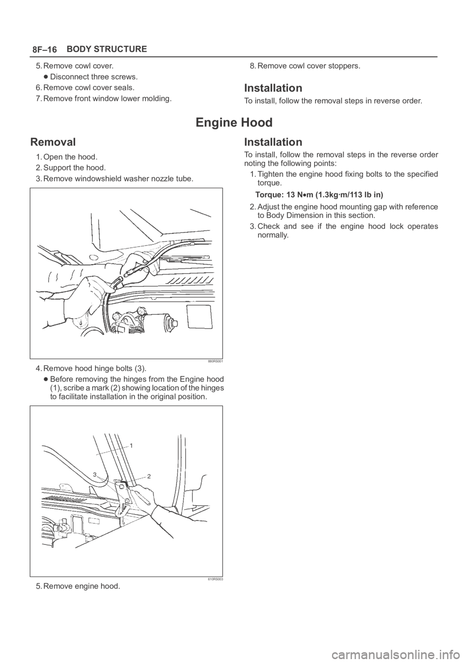
3. Remove windowshield washer nozzle tube.
880RS001
4. Remove hood hinge bolts (3).
Before removing the hinges from the Engine hood
(1), scribe a mark (2) showing location of the hinges
to facilitate installation in the original position.
610RS003
5. Remove engine hood.
Installation
To install, follow the removal steps in the reverse order
noting the following points:
1. Tighten the engine hood fixing bolts to the specified
torque.
To r q u e : 1 3 N
m (1.3kgꞏm/113 lb in)
2. Adjust the engine hood mounting gap with reference
to Body Dimension in this section.
3. Check and see if the engine hood lock operates
normally.
Page 3444 of 6000
SUPPLEMENTAL RESTRAINT SYSTEM9J–7
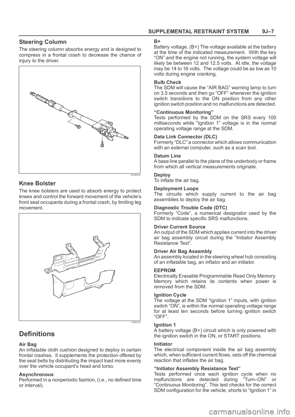
Steering Column
The steering column absorbs energy and is designed to
compress in a frontal crash to decrease the chance of
injury to the driver.
431RW019
Knee Bolster
The knee bolsters are used to absorb energy to protect
knees and control the forward movement of the vehicle’s
front seat occupants during a frontal crash, by limiting leg
movement.
740RT015
Definitions
Air Bag
An inflatable cloth cushion designed to deploy in certain
frontal crashes. It supplements the protection offered by
the seat belts by distributing the impact load more evenly
over the vehicle occupant’s head and torso.
Asynchronous
Performed in a nonperiodic fashion, (i.e., no defined time
or interval).B+
Battery voltage, (B+) The voltage available at the battery
at the time of the indicated measurement. With the key
“ON” and the engine not running, the system voltage will
likely be between 12 and 12.5 volts. At idle, the voltage
may be 14 to 16 volts. The voltage could be as low as 10
volts during engine cranking.
Bulb Check
The SDM will cause the “AIR BAG” warning lamp to turn
on 3.5 seconds and then go “OFF” whenever the ignition
switch transitions to the ON position from any other
ignition switch position and no malfunctions are detected.
“Continuous Monitoring”
Tests performed by the SDM on the SRS every 100
milliseconds while “Ignition 1” voltage is in the normal
operating voltage range at the SDM.
Data Link Connector (DLC)
Formerly “DLC” a connector which allows communication
with an external computer, such as a scan tool.
Datum Line
A base line parallel to the plane of the underbody or frame
from which all vertical measurements originate.
Deploy
To inflate the air bag.
Deployment Loops
The circuits which supply current to the air bag
assemblies to deploy the air bag.
Diagnostic Trouble Code (DTC)
Formerly “Code”, a numerical designator used by the
SDM to indicate specific SRS malfunctions.
Driver Current Source
An output of the SDM which applies current into the driver
air bag assembly circuit during the “Initiator Assembly
Resistance Test”.
Driver Air Bag Assembly
An assembly located in the steering wheel hub consisting
of an inflatable bag, an inflator and an initiator.
EEPROM
Electrically Erasable Programmable Read Only Memory.
Memory which retains its contents when power is
removed from the SDM.
Ignition Cycle
The voltage at the SDM “Ignition 1” inputs, with ignition
switch “ON”, is within the normal operating voltage range
for at least ten seconds before turning ignition switch
“OFF”.
Ignition 1
A battery voltage (B+) circuit which is only powered with
the ignition switch in the ON, or START positions.
Initiator
The electrical component inside the air bag assembly
which, when sufficient current flows, sets off the chemical
reaction that inflates the air bag.
“Initiator Assembly Resistance Test”
Tests performed once each ignition cycle when no
malfunctions are detected during “Turn–ON” or
“Continuous Monitoring”. This test checks for the correct
SDM configuration for the vehicle, shorts to “Ignition 1” in