Page 4945 of 6000

6E–288
ENGINE DRIVEABILITY AND EMISSIONS
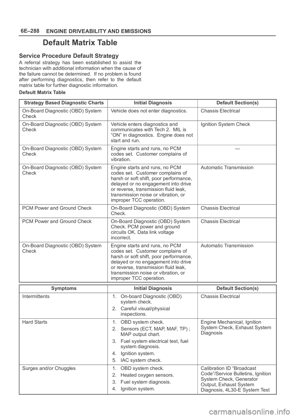
Default Matrix Table
Service Procedure Default Strategy
A referral strategy has been established to assist the
technician with additional information when the cause of
the failure cannot be determined. If no problem is found
after performing diagnostics, then refer to the default
matrix table for further diagnostic information.
Default Matrix Table
Strategy Based Diagnostic Charts
Initial DiagnosisDefault Section(s)
On-Board Diagnostic (OBD) System
CheckVehicle does not enter diagnostics.Chassis Electrical
On-Board Diagnostic (OBD) System
CheckVehicle enters diagnostics and
communicates with Tech 2. MIL is
“ON” in diagnostics. Engine does not
start and run.Ignition System Check
On-Board Diagnostic (OBD) System
CheckEngine starts and runs, no PCM
codes set. Customer complains of
vibration.—
On-Board Diagnostic (OBD) System
CheckEngine starts and runs, no PCM
codes set. Customer complains of
harsh or soft shift, poor performance,
delayed or no engagement into drive
or reverse, transmission fluid leak,
transmission noise or vibration, or
improper TCC operation.Automatic Transmission
PCM Power and Ground CheckOn-Board Diagnostic (OBD) System
Check.Chassis Electrical
PCM Power and Ground CheckOn-Board Diagnostic (OBD) System
Check. PCM power and ground
circuits OK. Data link voltage
incorrect.Chassis Electrical
On-Board Diagnostic (OBD) System
CheckEngine starts and runs, no PCM
codes set. Customer complains of
harsh or soft shift, poor performance,
delayed or no engagement into drive
or reverse, transmission fluid leak,
transmission noise or vibration, or
improper TCC operation.Automatic Transmission
SymptomsInitial DiagnosisDefault Section(s)
Intermittents1. On-board Diagnostic (OBD)
system check.
2. Careful visual/physical
inspections.Chassis Electrical
Hard Starts1. OBD system check.
2. Sensors (ECT, MAP, MAF, TP) ;
MAP output chart.
3. Fuel system electrical test, fuel
system diagnosis.
4. Ignition system.
5. IAC system check.Engine Mechanical, Ignition
System Check, Exhaust System
Diagnosis
Surges and/or Chuggles1. OBD system check.
2. Heated oxygen sensors.
3. Fuel system diagnosis.
4. Ignition system.Calibration ID “Broadcast
Code”/Service Bulletins, Ignition
System Check, Generator
Output, Exhaust System
Diagnosis, 4L30-E System Test
Page 4946 of 6000

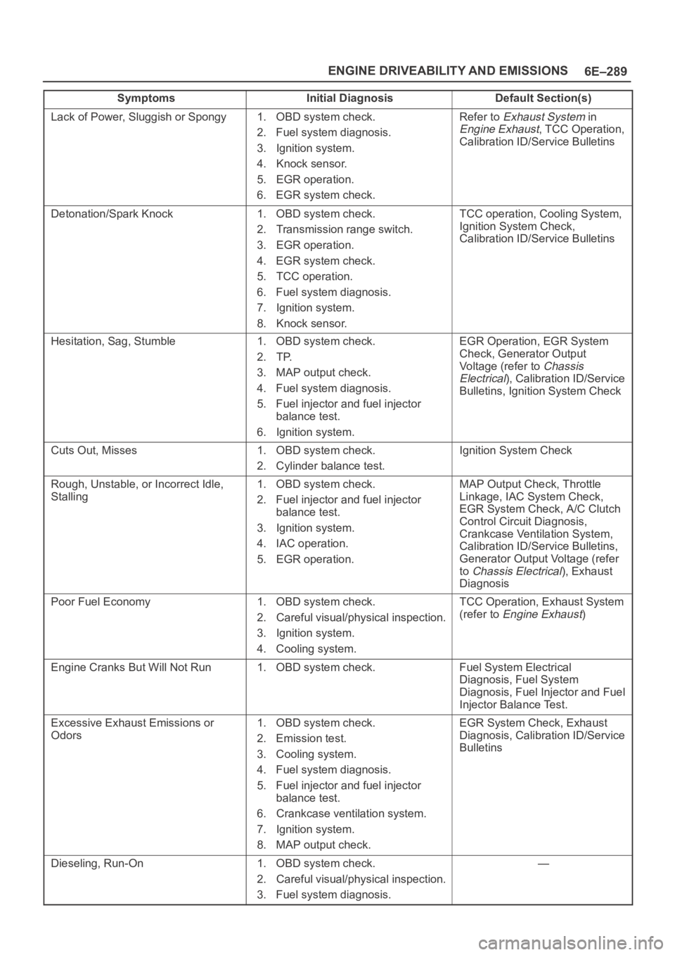
6E–289 ENGINE DRIVEABILITY AND EMISSIONS
Symptoms Default Section(s)Initial Diagnosis
Lack of Power, Sluggish or Spongy1. OBD system check.
2. Fuel system diagnosis.
3. Ignition system.
4. Knock sensor.
5. EGR operation.
6. EGR system check.Refer to Exhaust System in
Engine Exhaust, TCC Operation,
Calibration ID/Service Bulletins
Detonation/Spark Knock1. OBD system check.
2. Transmission range switch.
3. EGR operation.
4. EGR system check.
5. TCC operation.
6. Fuel system diagnosis.
7. Ignition system.
8. Knock sensor.TCC operation, Cooling System,
Ignition System Check,
Calibration ID/Service Bulletins
Hesitation, Sag, Stumble1. OBD system check.
2. TP.
3. MAP output check.
4. Fuel system diagnosis.
5. Fuel injector and fuel injector
balance test.
6. Ignition system.EGR Operation, EGR System
Check, Generator Output
Voltage (refer to
Chassis
Electrical
), Calibration ID/Service
Bulletins, Ignition System Check
Cuts Out, Misses1. OBD system check.
2. Cylinder balance test.Ignition System Check
Rough, Unstable, or Incorrect Idle,
Stalling1. OBD system check.
2. Fuel injector and fuel injector
balance test.
3. Ignition system.
4. IAC operation.
5. EGR operation.MAP Output Check, Throttle
Linkage, IAC System Check,
EGR System Check, A/C Clutch
Control Circuit Diagnosis,
Crankcase Ventilation System,
Calibration ID/Service Bulletins,
Generator Output Voltage (refer
to
Chassis Electrical), Exhaust
Diagnosis
Poor Fuel Economy1. OBD system check.
2. Careful visual/physical inspection.
3. Ignition system.
4. Cooling system.TCC Operation, Exhaust System
(refer to
Engine Exhaust)
Engine Cranks But Will Not Run1. OBD system check.Fuel System Electrical
Diagnosis, Fuel System
Diagnosis, Fuel Injector and Fuel
Injector Balance Test.
Excessive Exhaust Emissions or
Odors1. OBD system check.
2. Emission test.
3. Cooling system.
4. Fuel system diagnosis.
5. Fuel injector and fuel injector
balance test.
6. Crankcase ventilation system.
7. Ignition system.
8. MAP output check.EGR System Check, Exhaust
Diagnosis, Calibration ID/Service
Bulletins
Dieseling, Run-On1. OBD system check.
2. Careful visual/physical inspection.
3. Fuel system diagnosis.—
Page 4947 of 6000
6E–290
ENGINE DRIVEABILITY AND EMISSIONS
Symptoms Default Section(s)Initial Diagnosis
Backfire1. OBD system check.
2. Ignition system.
3. Fuel system diagnosis.
4. Fuel injector and fuel injector
balance test.
5. EGR operation, EGR system
check.Exhaust System Diagnosis,
Intake Casting Flash, Ignition
System Check
Catalyst Monitor1. OBD system check.
2. Careful visual/physical inspection.
3. Heated oxygen sensors.Exhaust System
Fuel Trim1. OBD system check.
2. Careful visual/physical inspection.
3. Fuel system diagnosis.
4. Heated oxygen sensors, MAF
sensors.Exhaust System Intake Air
System
Evaporative Emissions1. OBD system check.
2. Careful visual/physical inspection.
3. Fuel system diagnosis.—
Heated Oxygen Sensors1. OBD system check.
2. Careful visual/physical inspection.Exhaust System
Page 4949 of 6000

6E–292
ENGINE DRIVEABILITY AND EMISSIONS
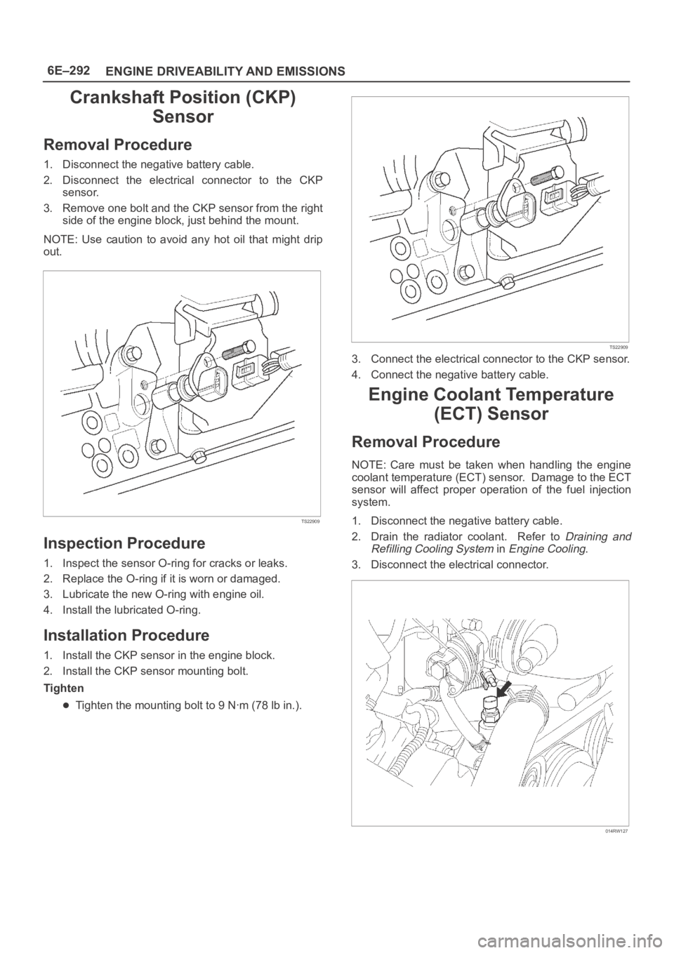
Crankshaft Position (CKP)
Sensor
Removal Procedure
1. Disconnect the negative battery cable.
2. Disconnect the electrical connector to the CKP
sensor.
3. Remove one bolt and the CKP sensor from the right
side of the engine block, just behind the mount.
NOTE: Use caution to avoid any hot oil that might drip
out.
TS22909
Inspection Procedure
1. Inspect the sensor O-ring for cracks or leaks.
2. Replace the O-ring if it is worn or damaged.
3. Lubricate the new O-ring with engine oil.
4. Install the lubricated O-ring.
Installation Procedure
1. Install the CKP sensor in the engine block.
2. Install the CKP sensor mounting bolt.
Tighten
Tighten the mounting bolt to 9 Nꞏm (78 lb in.).
TS22909
3. Connect the electrical connector to the CKP sensor.
4. Connect the negative battery cable.
Engine Coolant Temperature
(ECT) Sensor
Removal Procedure
NOTE: Care must be taken when handling the engine
coolant temperature (ECT) sensor. Damage to the ECT
sensor will affect proper operation of the fuel injection
system.
1. Disconnect the negative battery cable.
2. Drain the radiator coolant. Refer to
Draining and
Refilling Cooling System
in Engine Cooling.
3. Disconnect the electrical connector.
014RW127
Page 4967 of 6000

6E–310
ENGINE DRIVEABILITY AND EMISSIONS
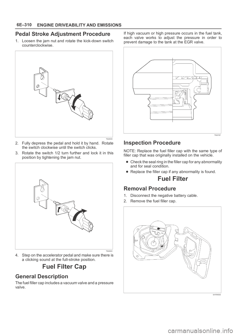
Pedal Stroke Adjustment Procedure
1. Loosen the jam nut and rotate the kick-down switch
counterclockwise.
TS24039
2. Fully depress the pedal and hold it by hand. Rotate
the switch clockwise until the switch clicks.
3. Rotate the switch 1/2 turn further and lock it in this
position by tightening the jam nut.
TS24040
4. Step on the accelerator pedal and make sure there is
a clicking sound at the full-stroke position.
Fuel Filter Cap
General Description
The fuel filler cap includes a vacuum valve and a pressure
valve.If high vacuum or high pressure occurs in the fuel tank,
each valve works to adjust the pressure in order to
prevent damage to the tank at the EGR valve.
TS23767
Inspection Procedure
NOTE: Replace the fuel filler cap with the same type of
filler cap that was originally installed on the vehicle.
Check the seal ring in the filler cap for any abnormality
and for seal condition.
Replace the filler cap if any abnormality is found.
Fuel Filter
Removal Procedure
1. Disconnect the negative battery cable.
2. Remove the fuel filler cap.
041RW005
Page 4968 of 6000
6E–311 ENGINE DRIVEABILITY AND EMISSIONS
3. Disconnect the fuel line from the fuel filter on the
engine side.
4. Disconnect the fuel line from the fuel filter on the fuel
tank side.
041RW006
5. Remove the bolt on the fuel filter holder.
041RW007
6. Remove the fuel filter.
041RW008
Inspection Procedure
1. Replace the fuel filter when the following occur:
Fuel leaks from the fuel filter body.
The fuel filter body is damaged.
The fuel filter is clogged with dirt or sediment.
2. If the drain hole is clogged, clean the drain.
041RW009
Page 4969 of 6000
6E–312
ENGINE DRIVEABILITY AND EMISSIONS
Installation Procedure
1. Install the fuel filter in the correct direction.
041RW008
2. Install the bolt on the fuel filter holder.
041RW007
3. Connect the fuel line on the engine side.
4. Connect the fuel line on the fuel tank side.
041RW006
5. Install the fuel filler cap.
041RW005
6. Connect the negative battery cable.
Page 4970 of 6000
6E–313 ENGINE DRIVEABILITY AND EMISSIONS
Fuel Gauge Unit
Removal Procedure
1. Disconnect the negative battery cable.
2. Loosen the fuel filler cap.
3. Drain the fuel from the tank.
Tighten
Tighten the drain plug to 20 Nꞏm (14 lb ft.).
TS22907
4. Disconnect the wiring connector from the fuel gauge
unit.
TS23771
5. Remove the fuel gauge unit retaining screws.
6. Remove the fuel gauge unit.
Cover or plug the fuel tank to prevent dust, dirt, or
debris from entering the tank.
TS22911
Installation Procedure
1. Install the fuel gauge unit.
2. Install the fuel gauge unit retaining screws.
TS22911