1998 OPEL FRONTERA torque
[x] Cancel search: torquePage 3529 of 6000
RESTRAINT CONTROL SYSTEM 9J1–42
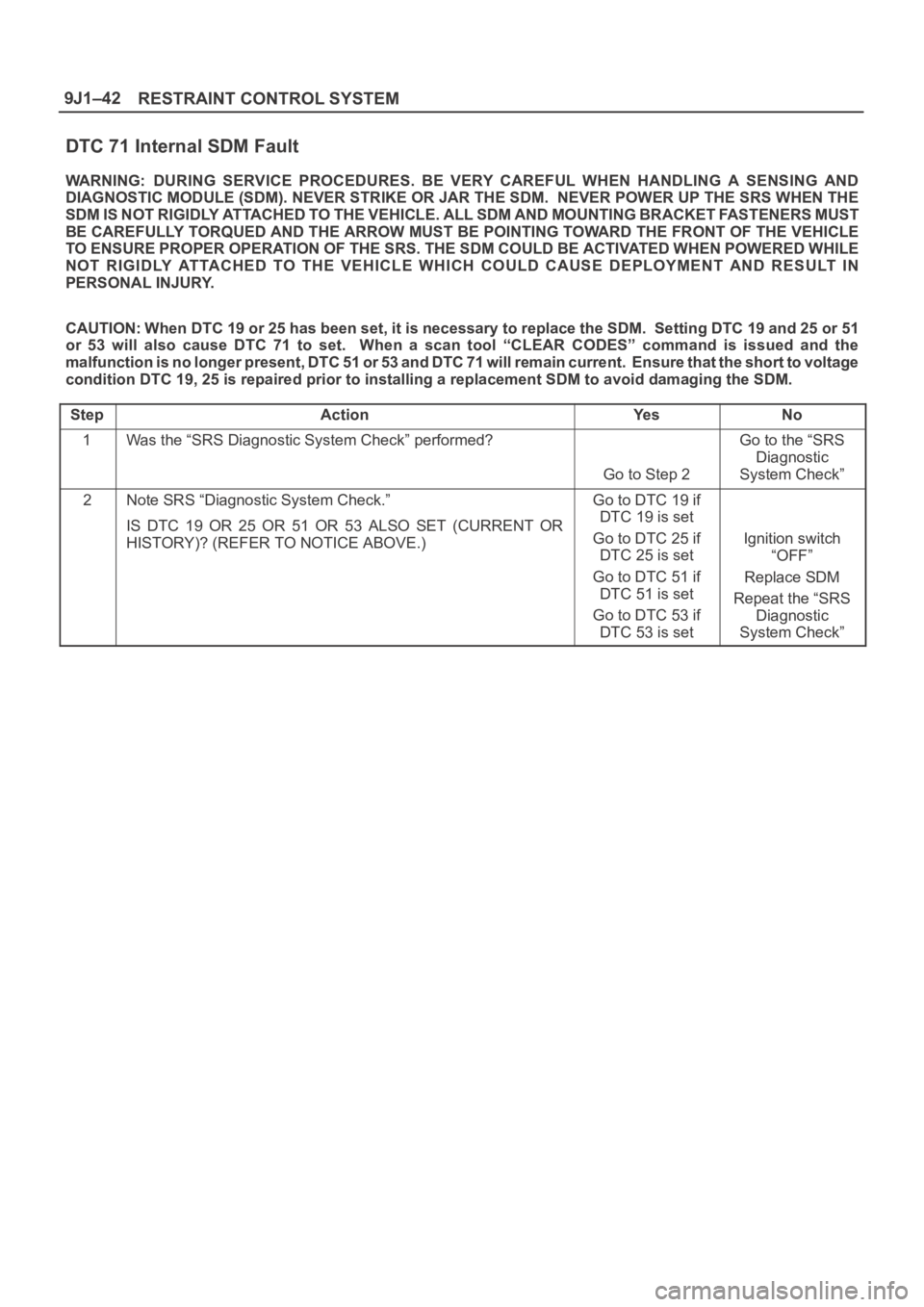
DTC 71 Internal SDM Fault
WARNING: DURING SERVICE PROCEDURES. BE VERY CAREFUL WHEN HANDLING A SENSING AND
DIAGNOSTIC MODULE (SDM). NEVER STRIKE OR JAR THE SDM. NEVER POWER UP THE SRS WHEN THE
SDM IS NOT RIGIDLY ATTACHED TO THE VEHICLE. ALL SDM AND MOUNTING BRACKET FASTENERS MUST
BE CAREFULLY TORQUED AND THE ARROW MUST BE POINTING TOWARD THE FRONT OF THE VEHICLE
TO ENSURE PROPER OPERATION OF THE SRS. THE SDM COULD BE ACTIVATED WHEN POWERED WHILE
NOT RIGIDLY ATTACHED TO THE VEHICLE WHICH COULD CAUSE DEPLOYMENT AND RESULT IN
PERSONAL INJURY.
CAUTION: When DTC 19 or 25 has been set, it is necessary to replace the SDM. Setting DTC 19 and 25 or 51
or 53 will also cause DTC 71 to set. When a scan tool “CLEAR CODES” command is issued and the
malfunction is no longer present, DTC 51 or 53 and DTC 71 will remain current. Ensure that the short to voltage
condition DTC 19, 25 is repaired prior to installing a replacement SDM to avoid damaging the SDM.
Step
ActionYe sNo
1Was the “SRS Diagnostic System Check” performed?
Go to Step 2
Go to the “SRS
Diagnostic
System Check”
2Note SRS “Diagnostic System Check.”
IS DTC 19 OR 25 OR 51 OR 53 ALSO SET (CURRENT OR
HISTORY)? (REFER TO NOTICE ABOVE.)Go to DTC 19 if
DTC 19 is set
Go to DTC 25 if
DTC 25 is set
Go to DTC 51 if
DTC 51 is set
Go to DTC 53 if
DTC 53 is set
Ignition switch
“OFF”
Replace SDM
Repeat the “SRS
Diagnostic
System Check”
Page 3551 of 6000
RESTRAINT CONTROL SYSTEM 9J1–64
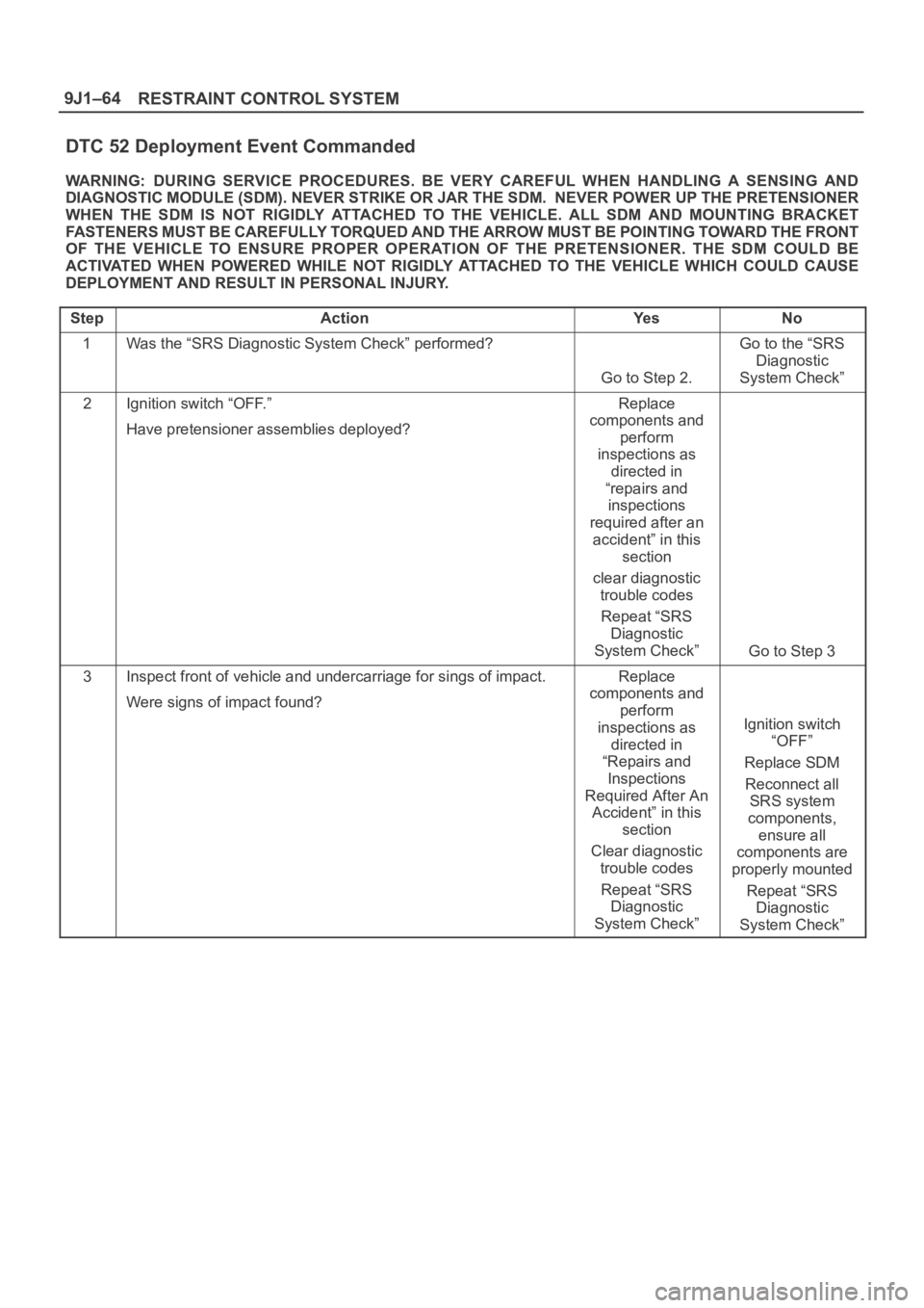
DTC 52 Deployment Event Commanded
WARNING: DURING SERVICE PROCEDURES. BE VERY CAREFUL WHEN HANDLING A SENSING AND
DIAGNOSTIC MODULE (SDM). NEVER STRIKE OR JAR THE SDM. NEVER POWER UP THE PRETENSIONER
WHEN THE SDM IS NOT RIGIDLY ATTACHED TO THE VEHICLE. ALL SDM AND MOUNTING BRACKET
FASTENERS MUST BE CAREFULLY TORQUED AND THE ARROW MUST BE POINTING TOWARD THE FRONT
OF THE VEHICLE TO ENSURE PROPER OPERATION OF THE PRETENSIONER. THE SDM COULD BE
ACTIVATED WHEN POWERED WHILE NOT RIGIDLY ATTACHED TO THE VEHICLE WHICH COULD CAUSE
DEPLOYMENT AND RESULT IN PERSONAL INJURY.
Step
ActionYe sNo
1Was the “SRS Diagnostic System Check” performed?
Go to Step 2.
Go to the “SRS
Diagnostic
System Check”
2Ignition switch “OFF.”
Have pretensioner assemblies deployed?Replace
components and
perform
inspections as
directed in
“repairs and
inspections
required after an
accident” in this
section
clear diagnostic
trouble codes
Repeat “SRS
Diagnostic
System Check”
Go to Step 3
3Inspect front of vehicle and undercarriage for sings of impact.
Were signs of impact found?Replace
components and
perform
inspections as
directed in
“Repairs and
Inspections
Required After An
Accident” in this
section
Clear diagnostic
trouble codes
Repeat “SRS
Diagnostic
System Check”
Ignition switch
“OFF”
Replace SDM
Reconnect all
SRS system
components,
ensure all
components are
properly mounted
Repeat “SRS
Diagnostic
System Check”
Page 3552 of 6000
10A–1
CRUISE CONTROL SYSTEM
CONTROL SYSTEM
CRUISE CONTROL SYSTEM
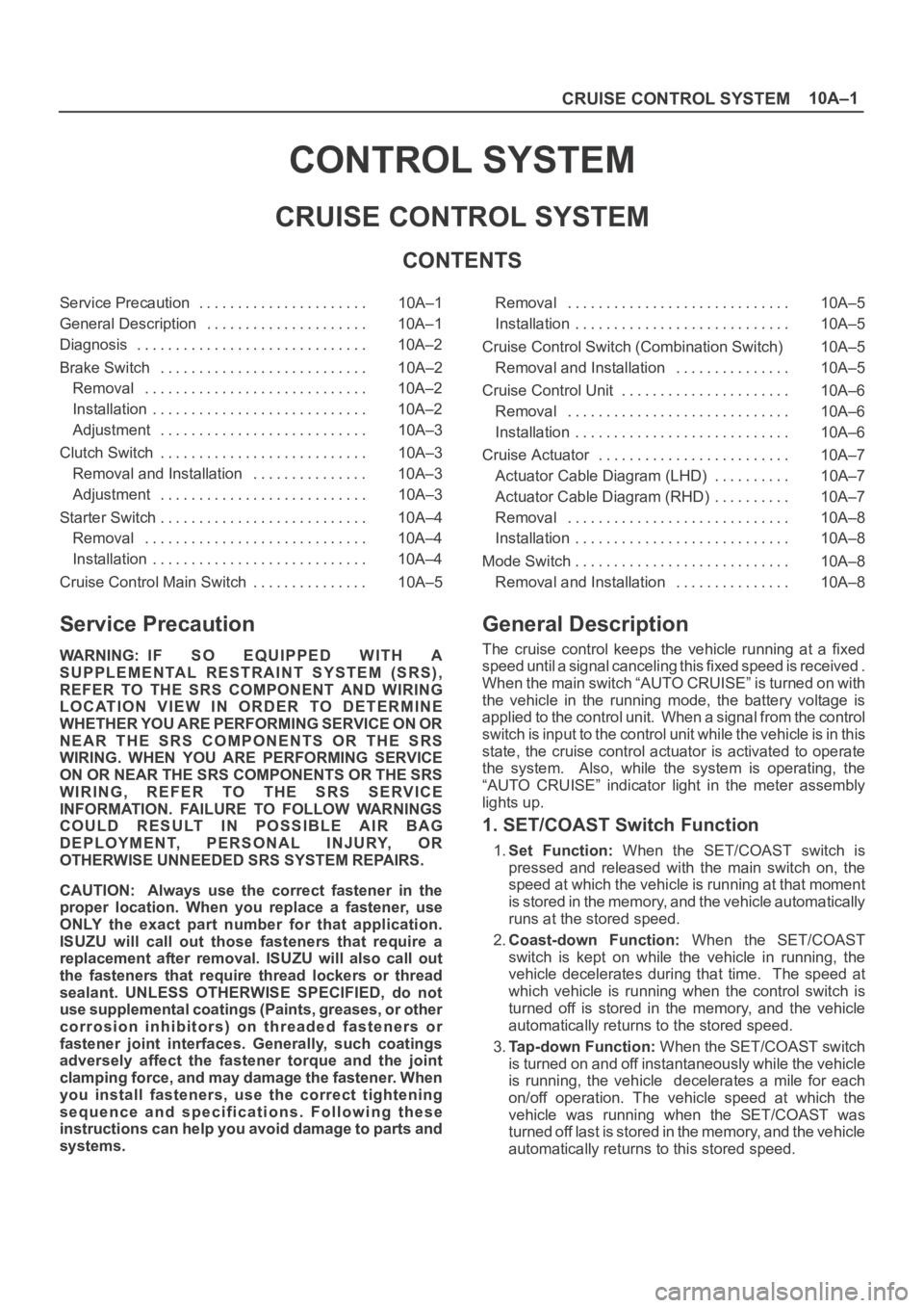
CONTENTS
Service Precaution 10A–1. . . . . . . . . . . . . . . . . . . . . .
General Description 10A–1. . . . . . . . . . . . . . . . . . . . .
Diagnosis 10A–2. . . . . . . . . . . . . . . . . . . . . . . . . . . . . .
Brake Switch 10A–2. . . . . . . . . . . . . . . . . . . . . . . . . . .
Removal 10A–2. . . . . . . . . . . . . . . . . . . . . . . . . . . . .
Installation 10A–2. . . . . . . . . . . . . . . . . . . . . . . . . . . .
Adjustment 10A–3. . . . . . . . . . . . . . . . . . . . . . . . . . .
Clutch Switch 10A–3. . . . . . . . . . . . . . . . . . . . . . . . . . .
Removal and Installation 10A–3. . . . . . . . . . . . . . .
Adjustment 10A–3. . . . . . . . . . . . . . . . . . . . . . . . . . .
Starter Switch 10A–4. . . . . . . . . . . . . . . . . . . . . . . . . . .
Removal 10A–4. . . . . . . . . . . . . . . . . . . . . . . . . . . . .
Installation 10A–4. . . . . . . . . . . . . . . . . . . . . . . . . . . .
Cruise Control Main Switch 10A–5. . . . . . . . . . . . . . . Removal 10A–5. . . . . . . . . . . . . . . . . . . . . . . . . . . . .
Installation 10A–5. . . . . . . . . . . . . . . . . . . . . . . . . . . .
Cruise Control Switch (Combination Switch) 10A–5
Removal and Installation 10A–5. . . . . . . . . . . . . . .
Cruise Control Unit 10A–6. . . . . . . . . . . . . . . . . . . . . .
Removal 10A–6. . . . . . . . . . . . . . . . . . . . . . . . . . . . .
Installation 10A–6. . . . . . . . . . . . . . . . . . . . . . . . . . . .
Cruise Actuator 10A–7. . . . . . . . . . . . . . . . . . . . . . . . .
Actuator Cable Diagram (LHD) 10A–7. . . . . . . . . .
Actuator Cable Diagram (RHD) 10A–7. . . . . . . . . .
Removal 10A–8. . . . . . . . . . . . . . . . . . . . . . . . . . . . .
Installation 10A–8. . . . . . . . . . . . . . . . . . . . . . . . . . . .
Mode Switch 10A–8. . . . . . . . . . . . . . . . . . . . . . . . . . . .
Removal and Installation 10A–8. . . . . . . . . . . . . . .
Service Precaution
WARNING: IF SO EQUIPPED WITH A
SUPPLEMENTAL RESTRAINT SYSTEM (SRS),
REFER TO THE SRS COMPONENT AND WIRING
LOCATION VIEW IN ORDER TO DETERMINE
WHETHER YOU ARE PERFORMING SERVICE ON OR
NEAR THE SRS COMPONENTS OR THE SRS
WIRING. WHEN YOU ARE PERFORMING SERVICE
ON OR NEAR THE SRS COMPONENTS OR THE SRS
WIRING, REFER TO THE SRS SERVICE
INFORMATION. FAILURE TO FOLLOW WARNINGS
COULD RESULT IN POSSIBLE AIR BAG
DEPLOYMENT, PERSONAL INJURY, OR
OTHERWISE UNNEEDED SRS SYSTEM REPAIRS.
CAUTION: Always use the correct fastener in the
proper location. When you replace a fastener, use
ONLY the exact part number for that application.
ISUZU will call out those fasteners that require a
replacement after removal. ISUZU will also call out
the fasteners that require thread lockers or thread
sealant. UNLESS OTHERWISE SPECIFIED, do not
use supplemental coatings (Paints, greases, or other
corrosion inhibitors) on threaded fasteners or
fastener joint interfaces. Generally, such coatings
adversely affect the fastener torque and the joint
clamping force, and may damage the fastener. When
you install fasteners, use the correct tightening
sequence and specifications. Following these
instructions can help you avoid damage to parts and
systems.
General Description
The cruise control keeps the vehicle running at a fixed
speed until a signal canceling this fixed speed is received .
When the main switch “AUTO CRUISE” is turned on with
the vehicle in the running mode, the battery voltage is
applied to the control unit. When a signal from the control
switch is input to the control unit while the vehicle is in this
state, the cruise control actuator is activated to operate
the system. Also, while the system is operating, the
“AUTO CRUISE” indicator light in the meter assembly
lights up.
1. SET/COAST Switch Function
1.Set Function: When the SET/COAST switch is
pressed and released with the main switch on, the
speed at which the vehicle is running at that moment
is stored in the memory, and the vehicle automatically
runs at the stored speed.
2.Coast-down Function: When the SET/COAST
switch is kept on while the vehicle in running, the
vehicle decelerates during that time. The speed at
which vehicle is running when the control switch is
turned off is stored in the memory, and the vehicle
automatically returns to the stored speed.
3.Tap-down Function: When the SET/COAST switch
is turned on and off instantaneously while the vehicle
is running, the vehicle decelerates a mile for each
on/off operation. The vehicle speed at which the
vehicle was running when the SET/COAST was
turned off last is stored in the memory, and the vehicle
automatically returns to this stored speed.
Page 3573 of 6000

Service Precaution
WARNING: THIS VEHICLE HAS A SUPPLEMENTAL
RESTRAINT SYSTEM (SRS). REFER TO THE SRS
COMPONENT AND WIRING LOCATION VIEW IN
ORDER TO DETERMINE WHETHER YOU ARE
PERFORMING SERVICE ON OR NEAR THE SRS
COMPONENTS OR THE SRS WIRING. WHEN YOU
ARE PERFORMING SERVICE ON OR NEAR THE
SRS COMPONENTS OR THE SRS WIRING, REFER
TO THE SRS SERVICE INFORMATION. FAILURE
TO FOLLOW WARNINGS COULD RESULT IN
POSSIBLE AIR BAG DEPLOYMENT, PERSONAL
INJURY, OR OTHERWISE UNNEEDED SRS
SYSTEM REPAIRS.CAUTION: Always use the correct fastener in the
proper location. When you replace a fastener, use
ONLY the exact part number for that application.
ISUZU will call out those fasteners that require a
replacement after removal. ISUZU will also call out
the fasteners that require thread lockers or thread
sealant. UNLESS OTHERWISE SPECIFIED, do not
use supplemental coatings (Paints, greases, or
other corrosion inhibitors) on threaded fasteners
or fasteners joint interfaces. Generally, such
coatings adversely affect the fastener torque and
the joint clamping force, and may damage the
fastener. When you install fasteners, use the
correct tightening sequence and specification.
Following these instructions can help you avoid
damage to parts and systems.
Page 3586 of 6000

Service Precaution
WARNING: THIS VEHICLE HAS A SUPPLEMENTAL
RESTRAINT SYSTEM (SRS). REFER TO THE SRS
COMPONENT AND WIRING LOCATION VIEW IN
ORDER TO DETERMINE WHETHER YOU ARE
PERFORMING SERVICE ON OR NEAR THE SRS
COMPONENTS OR THE SRS WIRING. WHEN YOU
ARE PERFORMING SERVICE ON OR NEAR THE
SRS COMPONENTS OR THE SRS WIRING, REFER
TO THE SRS SERVICE INFORMATION. FAILURE
TO FOLLOW WARNINGS COULD RESULT IN
POSSIBLE AIR BAG DEPLOYMENT, PERSONAL
INJURY, OR OTHERWISE UNNEEDED SRS
SYSTEM REPAIRS.CAUTION: Always use the correct fastener in the
proper location. When you replace a fastener, use
ONLY the exact part number for that application.
ISUZU will call out those fasteners that require a
replacement after removal. ISUZU will also call out
the fasteners that require thread lockers or thread
sealant. UNLESS OTHERWISE SPECIFIED, do not
use supplemental coatings (Paints, greases, or
other corrosion inhibitors) on threaded fasteners
or fasteners joint interfaces. Generally, such
coatings adversely affect the fastener torque and
the joint clamping force, and may damage the
fastener. When you install fasteners, use the
correct tightening sequence and specification.
Following these instructions can help you avoid
damage to parts and systems.
Page 3767 of 6000
Inspection and Repair
Drive Plate
If the frictional surface shows signs of damage due to
excessive heat, the drive plate and pulley should be
replaced.
Pulley Assembly
Check the appearance of the pulley assembly. If the
frictional surface of the pulley shows signs of excessive
grooving due to slippage, both the pulley and drive
plate should be replaced. The frictional surfaces of the
pulley assembly should be cleaned with a suitable
solvent before reinstallation.
Coil
Check coil for loose connector or cracked insulation.
Installation
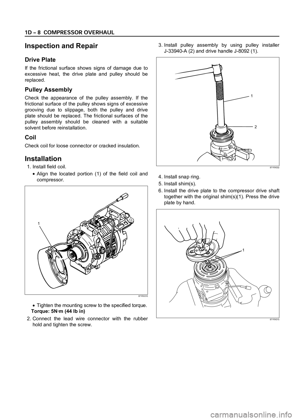
1. Install field coil.
Align the located portion (1) of the field coil and
compressor.
Tighten the mounting screw to the specified torque.
Torque: 5Nꞏm (44 lb in)
2. Connect the lead wire connector with the rubber
hold and tighten the screw.3. Install pulley assembly by using pulley installer
J-33940-A (2) and drive handle J-8092 (1).
4. Install snap ring.
5. Install shim(s).
6. Install the drive plate to the compressor drive shaft
together with the original shim(s)(1). Press the drive
plate by hand.
1
2
871RX032
1
871RX010
1
871RX015
Page 3768 of 6000
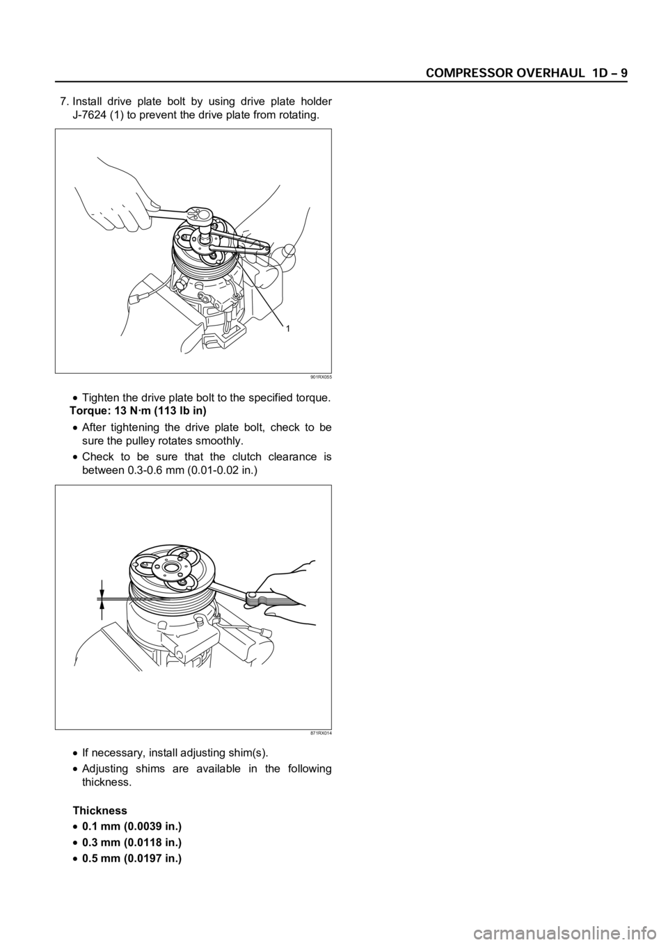
7. Install drive plate bolt by using drive plate holder
J-7624 (1) to prevent the drive plate from rotating.
Tighten the drive plate bolt to the specified torque.
Torque: 13 Nꞏm (113 lb in)
After tightening the drive plate bolt, check to be
sure the pulley rotates smoothly.
Check to be sure that the clutch clearance is
between 0.3-0.6 mm (0.01-0.02 in.)
If necessary, install adjusting shim(s).
Adjusting shims are available in the following
thickness.
Thickness
0.1 mm (0.0039 in.)
0.3 mm (0.0118 in.)
0.5 mm (0.0197 in.)
1
901RX055
871RX014
Page 3774 of 6000
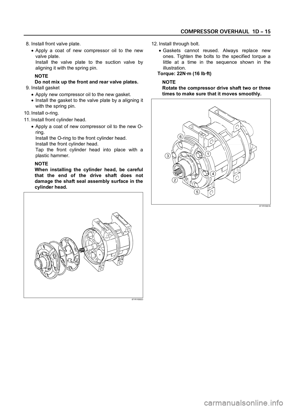
8. Install front valve plate.
Apply a coat of new compressor oil to the new
valve plate.
Install the valve plate to the suction valve by
aligning it with the spring pin.
NOTE
Do not mix up the front and rear valve plates.
9. Install gasket
Apply new compressor oil to the new gasket.
Install the gasket to the valve plate by a aligning it
with the spring pin.
10. Install o-ring.
11. Install front cylinder head.
Apply a coat of new compressor oil to the new O-
ring.
Install the O-ring to the front cylinder head.
Install the front cylinder head.
Tap the front cylinder head into place with a
plastic hammer.
NOTE
When installing the cylinder head, be careful
that the end of the drive shaft does not
damage the shaft seal assembly surface in the
cylinder head.12. Install through bolt.
Gaskets cannot reused. Always replace new
ones. Tighten the bolts to the specified torque a
little at a time in the sequence shown in the
illustration.
Torque: 22Nꞏm (16 lbꞏft)
NOTE
Rotate the compressor drive shaft two or three
times to make sure that it moves smoothly.
1
4
5
2
3
6
871RY00016
871RY00023