Page 5275 of 6000

6A – 2 ENGINE MECHANICAL
GENERAL DESCRIPTION
Cylinder Head Gasket
The cylinder head gasket is laminated steel sheets.
Three grades of the gasket according to the measured
piston head projection from the cylinder block are
provided to give the engine a minimum compression
ratio fluctuation.
Tightening Method for
Special Bolt
The cylinder head fixing bolts, flywheel bolts and
connecting rod cap fixing bolts are tightened by the
angular Tightening Method.
Piston
Auto-thermatic pistons having steel struts with a 0.4
mm offset from the piston pin center line, are applied to
reduce thermal expansion and resulting engine noise
when the engine is cold.
Bearings
The crankshaft bearings and connecting rod bearings
are of aluminum having a high bearing surface.
These bearings are especially sensitive to foreign
material such as metal scraps. So, it is very important
that the oil ports and other related surfaces are kept
clean and free of foreign material.
Crankshaft bearings are selected for optimum bearing
and journal clearance which reduces vebration and
noise.
Crankshaft
As tufftriding (Nitrizing treatment) is applied to increase
crankshaft strength, crankpins and journals should not
be reground.
Piston Cooling
An oiling jet device for piston cooling is provided in the
lubricating oil circuit from the cylinder block oil gallery
via a check valve.
Take care not to damage any oiling jet when removing
and installing piston and connecting assembly.
Fuel Injection System
The injection system is oil rail type.
Quick On Start 4 System
QOS4 preheating system which features a quick-on
glow plug with thermometer control of the glowing time
and the afterglow time function, is applied.
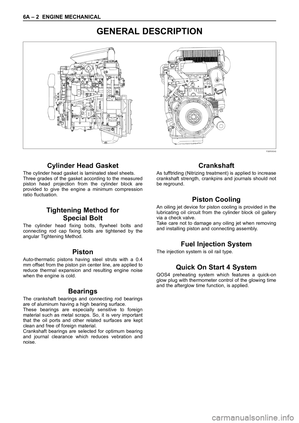
F06RW048
Page 5304 of 6000

ENGINE MECHANICAL 6A – 31
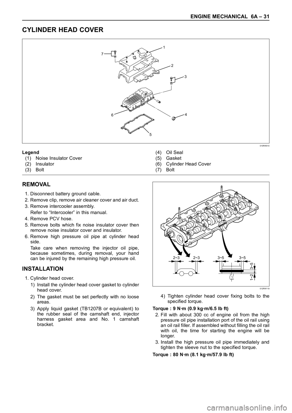
CYLINDER HEAD COVER
REMOVAL
1. Disconnect battery ground cable.
2. Remove clip, remove air cleaner cover and air duct.
3. Remove intercooler assembly.
Refer to “Intercooler” in this manual.
4. Remove PCV hose.
5. Remove bolts which fix noise insulator cover then
remove noise insulator cover and insulator.
6. Remove high pressure oil pipe at cylinder head
side.
Take care when removing the injector oil pipe,
because sometimes, during removal, your hand
can be injured by the remaining high pressure oil.
INSTALLATION
1. Cylinder head cover.
1) Install the cylinder head cover gasket to cylinder
head cover.
2) The gasket must be set perfectly with no loose
areas.
3) Apply liquid gasket (TB1207B or equivalent) to
the rubber seal of the camshaft end, injector
harness gasket area and No. 1 camshaft
bracket.4) Tighten cylinder head cover fixing bolts to the
specified torque.
Torque : 9 Nꞏm (0.9 kgꞏm/6.5 lb ft)
2. Fill with about 300 cc of engine oil from the high
pressure oil pipe installation port of the oil rail using
an oil rail filler. If assembled without filling the oil rail
with oil, the time for starting the engine will be
longer.
3. Install the high pressure oil pipe immediately and
tighten the sleeve nut to the specified torque.
Torque : 80 Nꞏm (8.1 kgꞏm/57.9 lb ft)
1
2
3 7
4
5 6
010RW010
Legend
(1) Noise Insulator Cover
(2) Insulator
(3) Bolt(4) Oil Seal
(5) Gasket
(6) Cylinder Head Cover
(7) Bolt
3~52~32~33~5
3~5 1~2
012RW119
Page 5306 of 6000

ENGINE MECHANICAL 6A – 33
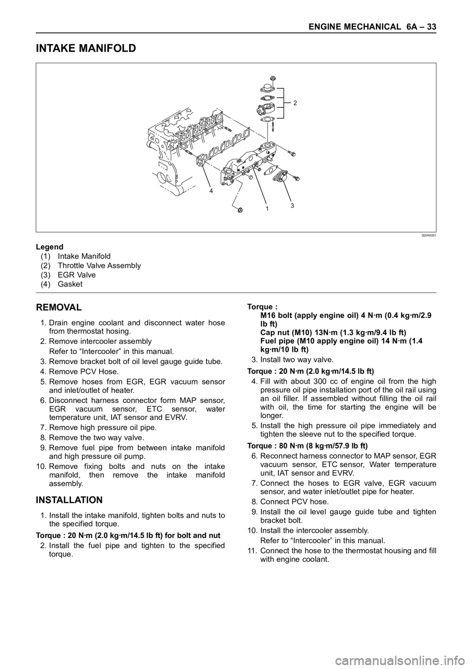
INTAKE MANIFOLD
REMOVAL
1. Drain engine coolant and disconnect water hose
from thermostat hosing.
2. Remove intercooler assembly
Refer to “Intercooler” in this manual.
3. Remove bracket bolt of oil level gauge guide tube.
4. Remove PCV Hose.
5. Remove hoses from EGR, EGR vacuum sensor
and inlet/outlet of heater.
6. Disconnect harness connector form MAP sensor,
EGR vacuum sensor, ETC sensor, water
temperature unit, IAT sensor and EVRV.
7. Remove high pressure oil pipe.
8. Remove the two way valve.
9. Remove fuel pipe from between intake manifold
and high pressure oil pump.
10. Remove fixing bolts and nuts on the intake
manifold, then remove the intake manifold
assembly.
INSTALLATION
1. Install the intake manifold, tighten bolts and nuts to
the specified torque.
Torque : 20 Nꞏm (2.0 kgꞏm/14.5 lb ft) for bolt and nut
2. Install the fuel pipe and tighten to the specified
torque.To r q u e :
M16 bolt (apply engine oil) 4 Nꞏm (0.4 kgꞏm/2.9
lb ft)
Cap nut (M10) 13Nꞏm (1.3 kgꞏm/9.4 lb ft)
Fuel pipe (M10 apply engine oil) 14 Nꞏm (1.4
kgꞏm/10 lb ft)
3. Install two way valve.
Torque : 20 Nꞏm (2.0 kgꞏm/14.5 lb ft)
4. Fill with about 300 cc of engine oil from the high
pressure oil pipe installation port of the oil rail using
an oil filler. If assembled without filling the oil rail
with oil, the time for starting the engine will be
longer.
5. Install the high pressure oil pipe immediately and
tighten the sleeve nut to the specified torque.
Torque : 80 Nꞏm (8 kgꞏm/57.9 lb ft)
6. Reconnect harness connector to MAP sensor, EGR
vacuum sensor, ETC sensor, Water temperature
unit, IAT sensor and EVRV.
7. Connect the hoses to EGR valve, EGR vacuum
sensor, and water inlet/outlet pipe for heater.
8. Connect PCV hose.
9. Install the oil level gauge guide tube and tighten
bracket bolt.
10. Install the intercooler assembly.
Refer to “Intercooler” in this manual.
11. Connect the hose to the thermostat housing and fill
with engine coolant.
2
3
4
1
025RX001
Legend
(1) Intake Manifold
(2) Throttle Valve Assembly
(3) EGR Valve
(4) Gasket
Page 5307 of 6000

6A – 34 ENGINE MECHANICAL
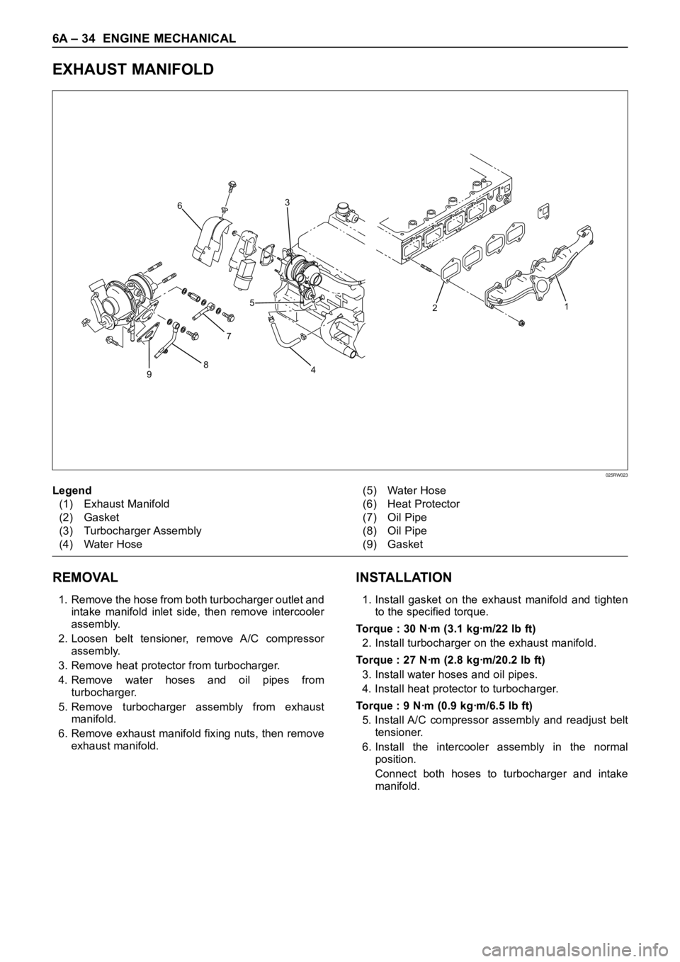
EXHAUST MANIFOLD
REMOVAL
1. Remove the hose from both turbocharger outlet and
intake manifold inlet side, then remove intercooler
assembly.
2. Loosen belt tensioner, remove A/C compressor
assembly.
3. Remove heat protector from turbocharger.
4.Remove water hoses and oil pipes from
turbocharger.
5. Remove turbocharger assembly from exhaust
manifold.
6. Remove exhaust manifold fixing nuts, then remove
exhaust manifold.
INSTALLATION
1. Install gasket on the exhaust manifold and tighten
to the specified torque.
Torque : 30 Nꞏm (3.1 kgꞏm/22 lb ft)
2. Install turbocharger on the exhaust manifold.
Torque : 27 Nꞏm (2.8 kgꞏm/20.2 lb ft)
3. Install water hoses and oil pipes.
4. Install heat protector to turbocharger.
Torque : 9 Nꞏm (0.9 kgꞏm/6.5 lb ft)
5. Install A/C compressor assembly and readjust belt
tensioner.
6. Install the intercooler assembly in the normal
position.
Connect both hoses to turbocharger and intake
manifold.
9875 63
21
4
025RW023
Legend
(1) Exhaust Manifold
(2) Gasket
(3) Turbocharger Assembly
(4) Water Hose(5) Water Hose
(6) Heat Protector
(7) Oil Pipe
(8) Oil Pipe
(9) Gasket
Page 5308 of 6000
ENGINE MECHANICAL 6A – 35
TURBOCHARGER
9875 63
21
4
025RW023
Legend
(1) Exhaust Manifold
(2) Gasket
(3) Turbocharger Assembly
(4) Water Hose(5) Water Hose
(6) Heat Protector
(7) Oil Pipe
(8) Oil Pipe
(9) Gasket
REMOVAL
1. Remove battery.
2. Drain engine coolant.
3. Remove air cleaner cover with air duct.
4. Remove intercooler assembly.
Refer to “Intercooler” in this manual.
5. Remove water pipe for turbocharger inlet.
6. Remove oil pipe for turbocharger.
1) Remove eye bolt from turbocharger.
2) Plug oil port on the turbocharger to prevent entry
of foreign materials.
7. Remove oil drain pipe from turbocharger.
8. Remove water outlet pipe.
9. Remove heat protector.
10. Remove exhaust adaptor.
11. Remove turbocharger assembly from exhaust
manifold.
036RW006
Page 5309 of 6000

6A – 36 ENGINE MECHANICAL
INSTALLATION
1. Install turbocharger assembly to exhaust manifold,
tighten to the specified torque.
Torque : 27 Nꞏm (2.8 kgꞏm/20.2 lb ft)
2. Install exhaust adaptor.
Torque : 27 Nꞏm (2.8 kgꞏm/20.2 lb ft)
3. Install heat protector.
4. Install water outlet pipe with gasket.
Torque : 9 Nꞏm (0.9 kgꞏm/6.5 lb ft)
5. Install turbocharger oil drain pipe.
Torque : 9 Nꞏm (0.9 kgꞏm/6.5 lb ft)6. Install oil supply pipe to turbocharger.
1) Fill with 100 cc engine oil at the turbocharger oil
supply hole before installing the oil pipe.
2) Turn the turbocharger by hand to lubricate
turbocharger shaft.
3) Install oil supply pipe with new gasket to the
turbocharger and tighten oil supply pipe bolts to
the specified torque.
Torque : 22 Nꞏm (2.2 kgꞏm/15.9 lb ft) for M10
54 Nꞏm (5.5 kgꞏm/39.8 lb ft) for M14
7. Install water inlet pipe with new gasket, tighten to
the specified torque.
Torque : 9 Nꞏm (0.9 kgꞏm/6.5 lb ft)
8. Install intercooler assembly.
Refer to “Intercooler” in this manual.
9. Install air cleaner cover with air duct, connect both
side hoses.
10. Fill with engine coolant.
11. Install the battery and connect battery cables.
036RW005
036RW005
036RW006
Page 5310 of 6000

ENGINE MECHANICAL 6A – 37
CYLINDER HEAD
3
4
1
2
012RW096
Legend
(1) Glow Plug
(2) Plate
(3) Cylinder Head Bolt
(4) Cylinder Head
NOTE:
During disassembly, be sure that the valve train
components are kept together and identified so that
they can be re-installed in their original locations.
Before removing the cylinder head from the engine
and before disassembling the valve mechanism, do
a compression test and note the results.
DISASSEMBLY
1. Injector Assy
2. Glow Plug and Glow Plug Connector
3. Cylinder Head Assembly
Refer to “Cylinder Head Gasket”
CLEAN
Cylinder head bolts
Cylinder head
Carefully remove all varnish, soot and carbon on
the bare metal. Do not use a motorized wire brush
on any gasket sealing surface.
INSPECTION AND REPAIR
Make the necessary adjustments, repairs, and part
replacements if excessive wear or damage is
discovered during inspection.
Cylinder head gasket and mating surfaces for
leaks, corrosion and blow-by. If the gasket has
failed, determine the cause;
– Improper installation
– Loosen or warped cylinder head
– Insufficient torque on head bolts
– Warped cylinder block surface
Page 5312 of 6000
ENGINE MECHANICAL 6A – 39
CYLINDER HEAD GASKET
12
13
14
15
1
2
3 7
4
5 6
10
11 9
8
011RW047-1
Legend
(1) Cylinder Head Noise Insulator Cover
(2) Insulator
(3) Bolt and Gasket
(4) Oil Seal
(5) Gasket
(6) Cylinder Head Cover
(7) Bolt and Gasket
(8) Injector Clamp(9) Oil Rail
(10) Injector Assembly
(11) Camshaft Carrier
(12) Cylinder Head Bolt
(13) Cylinder Head Assembly
(14) Cylinder Head Gasket
(15) Cylinder Block