1998 OPEL FRONTERA fuel
[x] Cancel search: fuelPage 2152 of 6000

INDUCTION 6J – 11
INTAKE MANIFOLD
REMOVAL
1. Drain engine coolant and remove water hose from
thermostat housing
2. Remove intercooler assembly.
3. Remove bracket fixing bolt of oil level gauge guide
tube.
4. Remove PCV hose.
5. Remove hoses from EGR valve, EGR vacuum
sensor and outlet of heater unit.
6. Disconnect harness connector from MAP sensor,
EGR vacuum sensor, ETC sensor, Water
temperature unit, IAT sensor and EVRV.
7. Remove high pressure oil pipe.
8. Remove two way check valve.
9. Remove fuel pipe.
10. Remove fixing bolts and nuts of intake manifold,
remove intake manifold assembly.
Legend
(1) Intake manifold
(2) Fixing portion of throttle valve
(3) EGR passage
(4) EGR valve
For Europe
2
1
3
3 1 42
Legend
(1) Intake Manifold
(2) Throttle Valve Assembly
(3) EGR Valve
(4) Gasket
025R200005
3124
025RW031
Page 2153 of 6000

6J – 12 INDUCTION
INSPECTION AND RAPAIR
1. Visually check for cracks/clogs inside intake
manifold.
2. If foreign material is observed, it should be taken
out, and if there are some cracks on the intake
manifold, it must be replaced.
INSTALLATION
1. Install the intake manifold assembly, tighten bolts
and to the specified torque.
Torque: 20 Nꞏm (2.0 kgꞏm / 14.5 lb ft) for bolt
Torque: 20 Nꞏm (2.0 kgꞏm / 14.5 lb ft) for nut
2. Install fuel pipe.
Torque: 4 Nꞏm (0.4 kgꞏm / 2.9 lb ft) for M16 nut
(Apply engine oil)
Torque: 13 Nꞏm (1.3 kgꞏm / 9.4 lb ft) for M10 cap nut
Torque: 14 Nꞏm (1.4 kgꞏm / 10 lb ft) for M10
(Apply engine oil)
3. Install two way check valve.
Torque: 20 Nꞏm (2.0 kgꞏm / 14.5 lb ft)
4. Fill with about 300 cc of engine oil from the high
pressure oil pipe installation port of the oil rail using
an oil filler.
If assembled without filling the oil rail with oil, the
time for engine starting will be longer.
5. Install high pressure oil pipe, then tighten sleeve nut
to the specified torque.
Torque: 29 Nꞏm (3.0 kgꞏm / 21.7 lb ft)
6. Reconnect harness connector to MAP sensor, EGR
vacuum sensor, ETC sensor, Water thermo unit,
IAT sensor and EVRV sensor.
7. Install hoses to EGR valve, EGR vacuum sensor
and Water outlet of heater.
8. Connect PCV hose.
9. Install oil level gauge guide and fix it.
10. Install intercooler assembly.
Refer to “Intercooler” in this manual.
11. Install water hose to thermostat housing and fill with
engine coolant.
Model of Turbocharger IHI RHF5
Turbine Maximum Speed 180,000 rpm
Maximum Inlet Gas Temperature 800 °C (1472 °F)
Vibration Peak (G) criteria Maximum 4 (G) at Turbine Rotor Speed 140,000 rpm
Tolerance Limit of Compressor Blade Height Less then 0.5 mm (0.0197 in)
MAIN DATA AND SPECIFICATIONS
Page 2186 of 6000
7A–32
AUTOMATIC TRANSMISSION (4L30–E)
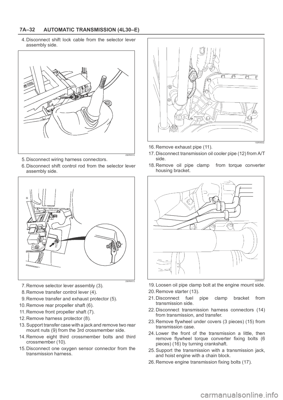
4. Disconnect shift lock cable from the selector lever
assembly side.
256RW012
5. Disconnect wiring harness connectors.
6. Disconnect shift control rod from the selector lever
assembly side.
256RW013
7. Remove selector lever assembly (3).
8. Remove transfer control lever (4).
9. Remove transfer and exhaust protector (5).
10. Remove rear propeller shaft (6).
11. Remove front propeller shaft (7).
12. Remove harness protector (8).
13. Support transfer case with a jack and remove two rear
mount nuts (9) from the 3rd crossmember side.
14. Remove eight third crossmember bolts and third
crossmember (10).
15. Disconnect one oxygen sensor connector from the
transmission harness.
150RW002
16. Remove exhaust pipe (11).
17. Disconnect transmission oil cooler pipe (12) from A/T
side.
18. Remove oil pipe clamp from torque converter
housing bracket.
253RW001
19. Loosen oil pipe clamp bolt at the engine mount side.
20. Remove starter (13).
21. Disconnect fuel pipe clamp bracket from
transmission side.
22. Disconnect transmission harness connectors (14)
from transmission, and transfer.
23. Remove flywheel under covers (3 pieces) (15) from
transmission case.
24. Lower the front of the transmission a little, then
remove flywheel torque converter fixing bolts (6
pieces) (16) by turning crankshaft.
25. Support the transmission with a transmission jack,
and hoist engine with a chain block.
26. Remove engine transmission fixing bolts (17).
Page 2188 of 6000
7A–34
AUTOMATIC TRANSMISSION (4L30–E)
5. Install the flywheel under cover (3 pieces), and tighten
the bolts to the specified torque.
Torque: 8 N
m (0.8 kgꞏm/69 lb in)
6. Install the starter, and tighten the bolts to the specified
torque.
Torque: 40 N
m (4.1 kgꞏm/30 lb ft)7. Connect transmission harness connectors to
transmission, and transfer.
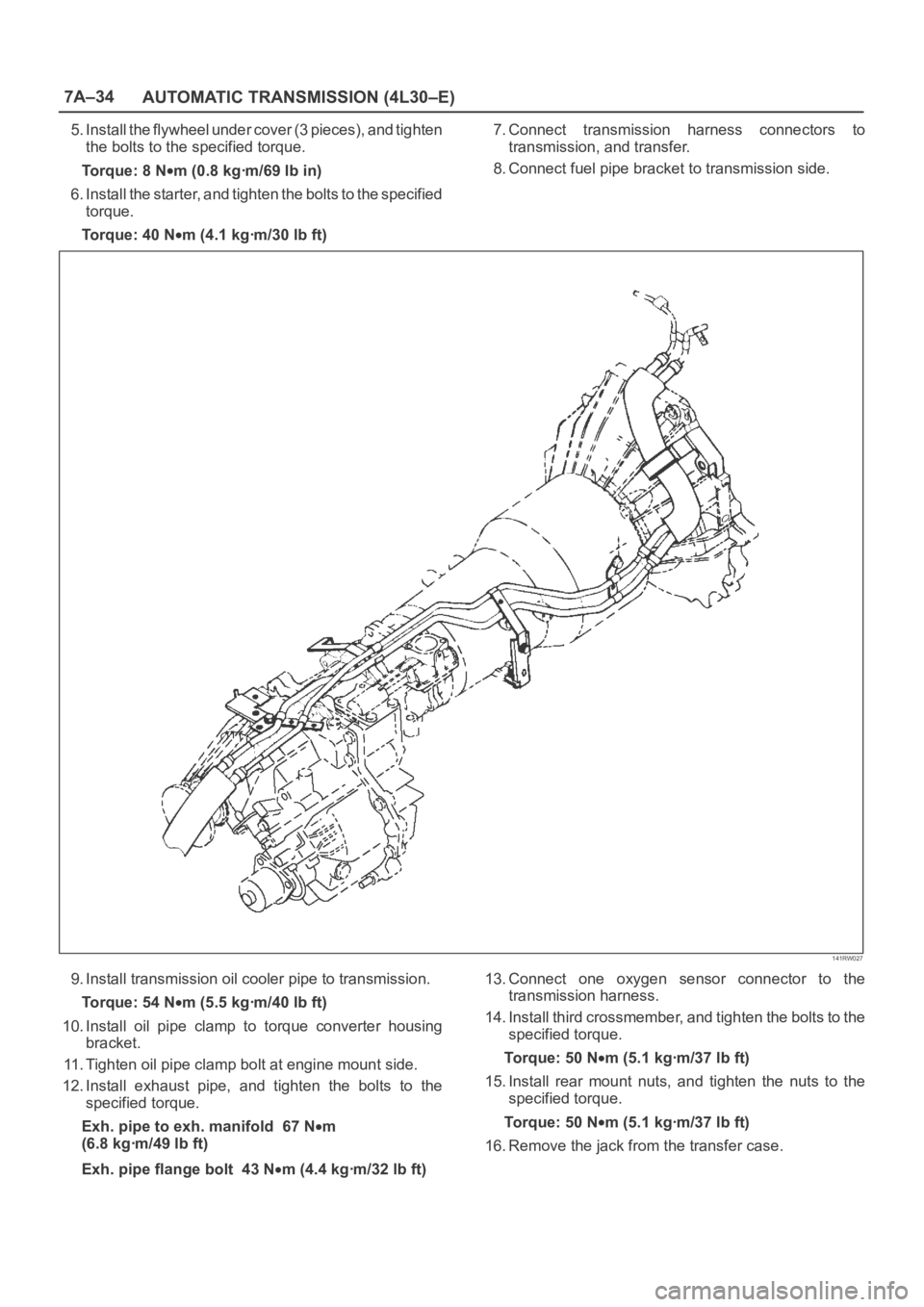
8. Connect fuel pipe bracket to transmission side.
141RW027
9. Install transmission oil cooler pipe to transmission.
Torque: 54 N
m (5.5 kgꞏm/40 lb ft)
10. Install oil pipe clamp to torque converter housing
bracket.
11. Tighten oil pipe clamp bolt at engine mount side.
12. Install exhaust pipe, and tighten the bolts to the
specified torque.
Exh. pipe to exh. manifold 67 N
m
(6.8 kgꞏm/49 lb ft)
Exh. pipe flange bolt 43 N
m (4.4 kgꞏm/32 lb ft)13. Connect one oxygen sensor connector to the
transmission harness.
14. Install third crossmember, and tighten the bolts to the
specified torque.
To r q u e : 5 0 N
m (5.1 kgꞏm/37 lb ft)
15. Install rear mount nuts, and tighten the nuts to the
specified torque.
To r q u e : 5 0 N
m (5.1 kgꞏm/37 lb ft)
16. Remove the jack from the transfer case.
Page 2247 of 6000
7A1–2
TRANSMISSION CONTROL SYSTEM (4L30–E)
Service Precaution
WARNING: IF SO EQUIPPED WITH A
SUPPLEMENTAL RESTRAINT SYSTEM (SRS),
REFER TO THE SRS COMPONENT AND WIRING
LOCATION VIEW IN ORDER TO DETERMINE
WHETHER YOU ARE PERFORMING SERVICE ON OR
NEAR THE SRS COMPONENTS OR THE SRS
WIRING. WHEN YOU ARE PERFORMING SERVICE
ON OR NEAR THE SRS COMPONENTS OR THE SRS
WIRING, REFER TO THE SRS SERVICE
INFORMATION. FAILURE TO FOLLOW WARNINGS
COULD RESULT IN POSSIBLE AIR BAG
DEPLOYMENT, PERSONAL INJURY, OR
OTHERWISE UNNEEDED SRS SYSTEM REPAIRS.
CAUTION: Always use the correct fastener in the
proper location. When you replace a fastener, use
ONLY the exact part number for that application.
ISUZU will call out those fasteners that require a
replacement after removal. ISUZU will also call out
the fasteners that require thread lockers or thread
sealant. UNLESS OTHERWISE SPECIFIED, do not
use supplemental coatings (Paints, greases, or other
corrosion inhibitors) on threaded fasteners or
fastener joint interfaces. Generally, such coatings
adversely affect the fastener torque and the joint
clamping force, and may damage the fastener. When
you install fasteners, use the correct tightening
sequence and specifications. Following these
instructions can help you avoid damage to parts and
systems.
General Description
The 4L30–E is a 4–speed fully automatic transmission. It
uses a microcomputer as a control unit to judge running
conditions including throttle opening rate and vehicle
speed, then it sets the shifting point in the optimum timing
so that best driving performance can be achieved.
In addition, the built–in shift mode select function can
select three shift modes according to the driver’s
preference:
Normal mode –Normal shift pattern.
Winter mode –Starts in 3rd gear to reduce slippage on
ice or snow.
Power mode has a delayed upshift for when more
powerful acceleration is required.
Also, the built–in fail safe function (“backup mode”)
assures driving performance even if the vehicle speed
sensor, throttle signal or any solenoid fails.
Further, the self–diagnostic function conducts diagnosis
in a short time when the control system fails, thus
improving serviceability.
The major features of 4L30–E are as follows:
A compact structure consisting of 2 sets of planetary
gears and flat torque converter.
Electronic control selects the optimum shift mode
according to the driving conditions.
Electronic control maintains the optimum hydraulic
pressure for clutch, band brake as well as
transmission so that shift feeling is improved.
Two sets of planetary gears reduce friction of power
train.
Also, a lockup mechanism in the torque converter
reduces fuel consumption.
Wide gear ratio and high torque rate of torque
converter provide excellent starting performance.
Page 2265 of 6000
7A1–20
TRANSMISSION CONTROL SYSTEM (4L30–E)
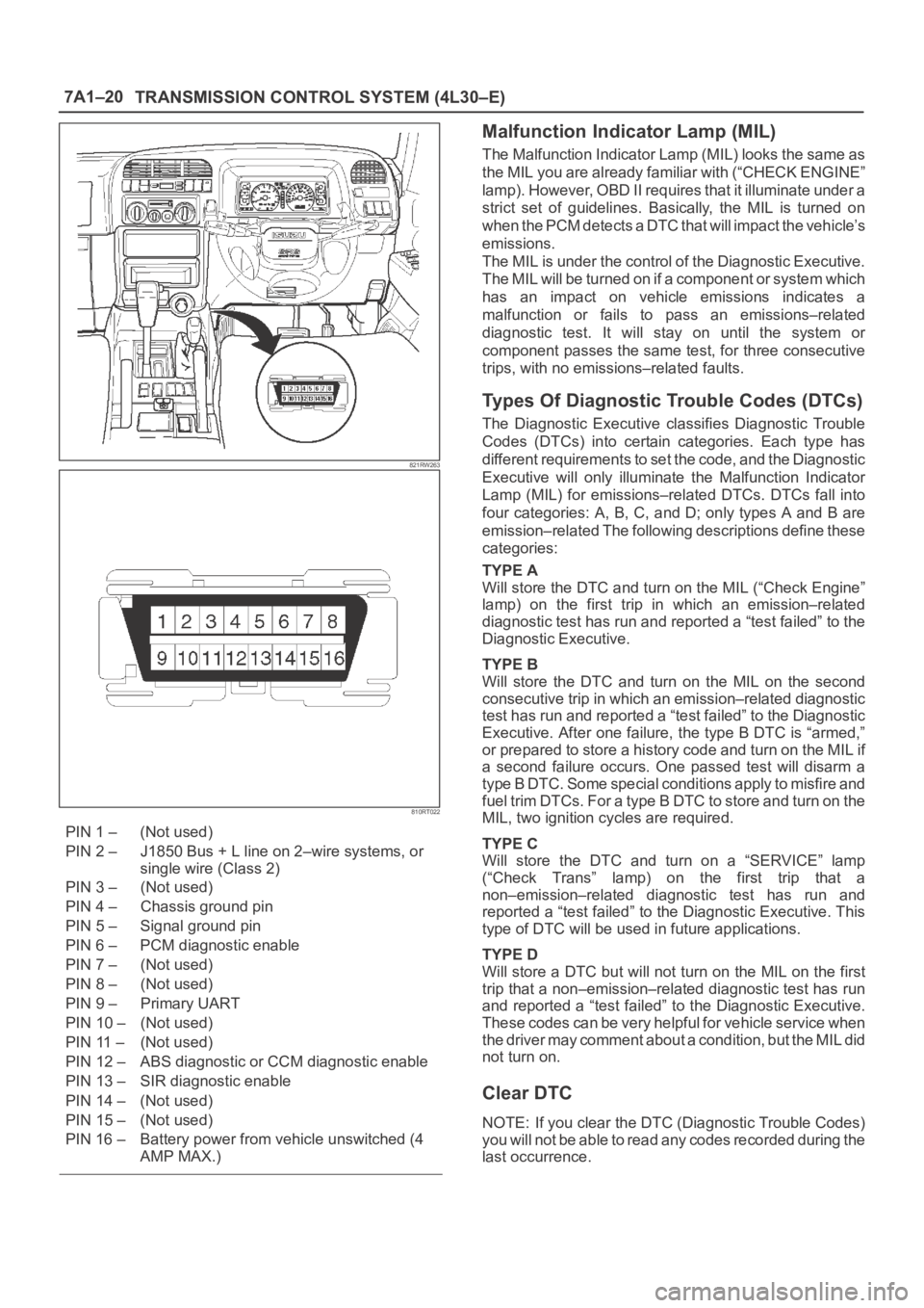
821RW263
810RT022
PIN 1 – (Not used)
PIN 2 – J1850 Bus + L line on 2–wire systems, or
single wire (Class 2)
PIN 3 – (Not used)
PIN 4 – Chassis ground pin
PIN 5 – Signal ground pin
PIN 6 – PCM diagnostic enable
PIN 7 – (Not used)
PIN 8 – (Not used)
PIN 9 – Primary UART
PIN 10 – (Not used)
PIN 11 – (Not used)
PIN 12 – ABS diagnostic or CCM diagnostic enable
PIN 13 – SIR diagnostic enable
PIN 14 – (Not used)
PIN 15 – (Not used)
PIN 16 – Battery power from vehicle unswitched (4
AMP MAX.)
Malfunction Indicator Lamp (MIL)
The Malfunction Indicator Lamp (MIL) looks the same as
the MIL you are already familiar with (“CHECK ENGINE”
lamp). However, OBD II requires that it illuminate under a
strict set of guidelines. Basically, the MIL is turned on
when the PCM detects a DTC that will impact the vehicle’s
emissions.
The MIL is under the control of the Diagnostic Executive.
The MIL will be turned on if a component or system which
has an impact on vehicle emissions indicates a
malfunction or fails to pass an emissions–related
diagnostic test. It will stay on until the system or
component passes the same test, for three consecutive
trips, with no emissions–related faults.
Types Of Diagnostic Trouble Codes (DTCs)
The Diagnostic Executive classifies Diagnostic Trouble
Codes (DTCs) into certain categories. Each type has
different requirements to set the code, and the Diagnostic
Executive will only illuminate the Malfunction Indicator
Lamp (MIL) for emissions–related DTCs. DTCs fall into
four categories: A, B, C, and D; only types A and B are
emission–related The following descriptions define these
categories:
TYPE A
Will store the DTC and turn on the MIL (“Check Engine”
lamp) on the first trip in which an emission–related
diagnostic test has run and reported a “test failed” to the
Diagnostic Executive.
TYPE B
Will store the DTC and turn on the MIL on the second
consecutive trip in which an emission–related diagnostic
test has run and reported a “test failed” to the Diagnostic
Executive. After one failure, the type B DTC is “armed,”
or prepared to store a history code and turn on the MIL if
a second failure occurs. One passed test will disarm a
type B DTC. Some special conditions apply to misfire and
fuel trim DTCs. For a type B DTC to store and turn on the
MIL, two ignition cycles are required.
TYPE C
Will store the DTC and turn on a “SERVICE” lamp
(“Check Trans” lamp) on the first trip that a
non–emission–related diagnostic test has run and
reported a “test failed” to the Diagnostic Executive. This
type of DTC will be used in future applications.
TYPE D
Will store a DTC but will not turn on the MIL on the first
trip that a non–emission–related diagnostic test has run
and reported a “test failed” to the Diagnostic Executive.
These codes can be very helpful for vehicle service when
the driver may comment about a condition, but the MIL did
not turn on.
Clear DTC
NOTE: If you clear the DTC (Diagnostic Trouble Codes)
you will not be able to read any codes recorded during the
last occurrence.
Page 2326 of 6000
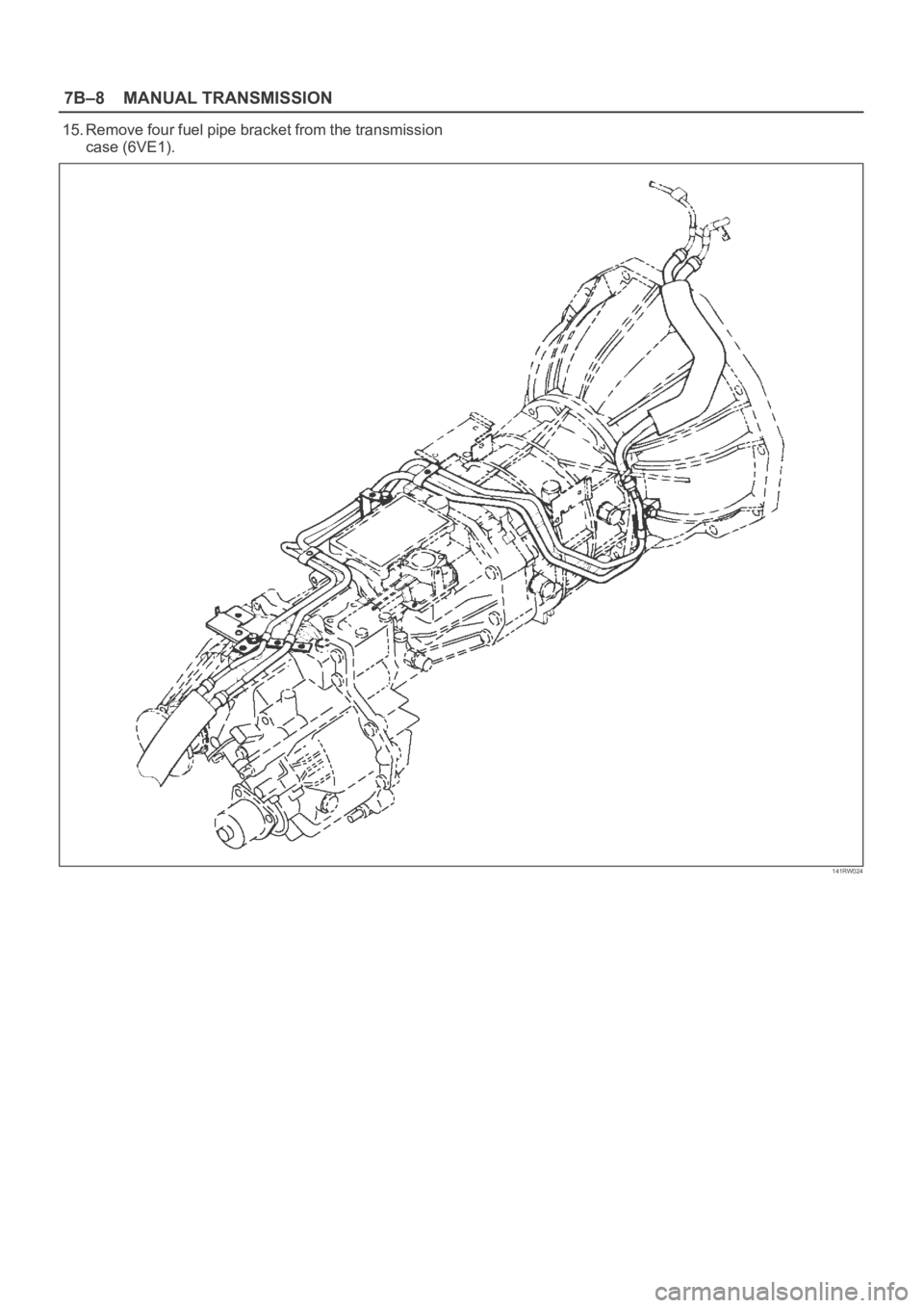
7B–8MANUAL TRANSMISSION
15. Remove four fuel pipe bracket from the transmission
case (6VE1).
141RW024
Page 2332 of 6000
7B–14MANUAL TRANSMISSION
7. Install the engine rear mount to the transmission case
and tighten the fixing bolts specified torque (6VE1).
Torque: 41 Nꞏm (4.2kgꞏm/30 Ib ft)
8. Install the third crossmember to the frame and tighten
the fixing bolts specified torque.
Torque: 50 Nꞏm (5.1kgꞏm/37 Ib ft)
9. Tighten the engine rear mount nuts specified torque.
Torque: 50 Nꞏm (5.1kgꞏm/37 Ib ft)
10. Remove the transmission jack.
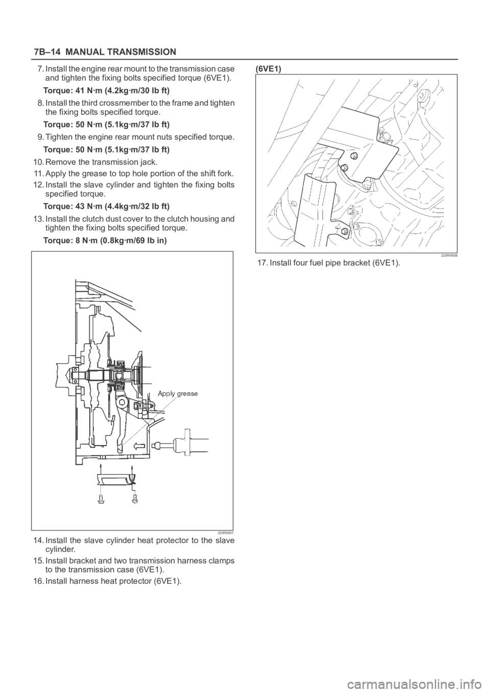
11. Apply the grease to top hole portion of the shift fork.
12. Install the slave cylinder and tighten the fixing bolts
specified torque.
Torque: 43 Nꞏm (4.4kgꞏm/32 Ib ft)
13. Install the clutch dust cover to the clutch housing and
tighten the fixing bolts specified torque.
Torque: 8 Nꞏm (0.8kgꞏm/69 Ib in)
220RS007
14. Install the slave cylinder heat protector to the slave
cylinder.
15. Install bracket and two transmission harness clamps
to the transmission case (6VE1).
16. Install harness heat protector (6VE1).(6VE1)
225RW006
17. Install four fuel pipe bracket (6VE1).