1998 OPEL FRONTERA engine coolant
[x] Cancel search: engine coolantPage 5001 of 6000
6E–344
ENGINE DRIVEABILITY AND EMISSIONS
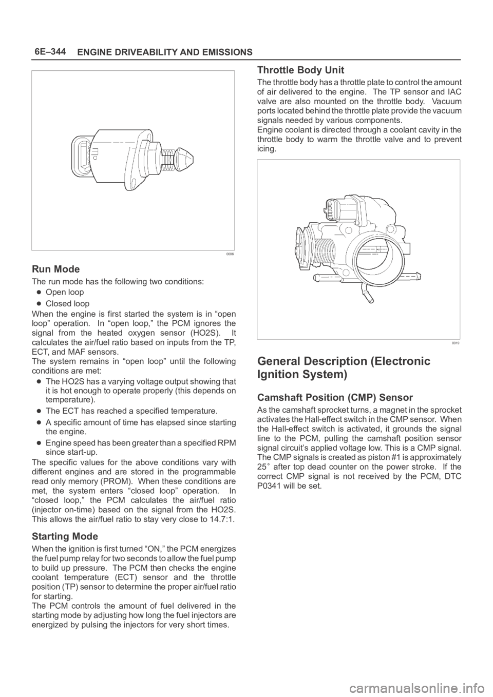
0006
Run Mode
The run mode has the following two conditions:
Open loop
Closed loop
When the engine is first started the system is in “open
loop” operation. In “open loop,” the PCM ignores the
signal from the heated oxygen sensor (HO2S). It
calculates the air/fuel ratio based on inputs from the TP,
ECT, and MAF sensors.
The system remains in “open loop” until the following
conditions are met:
The HO2S has a varying voltage output showing that
it is hot enough to operate properly (this depends on
temperature).
The ECT has reached a specified temperature.
A specific amount of time has elapsed since starting
the engine.
Engine speed has been greater than a specified RPM
since start-up.
The specific values for the above conditions vary with
different engines and are stored in the programmable
read only memory (PROM). When these conditions are
met, the system enters “closed loop” operation. In
“closed loop,” the PCM calculates the air/fuel ratio
(injector on-time) based on the signal from the HO2S.
This allows the air/fuel ratio to stay very close to 14.7:1.
Starting Mode
When the ignition is first turned “ON,” the PCM energizes
the fuel pump relay for two seconds to allow the fuel pump
to build up pressure. The PCM then checks the engine
coolant temperature (ECT) sensor and the throttle
position (TP) sensor to determine the proper air/fuel ratio
for starting.
The PCM controls the amount of fuel delivered in the
starting mode by adjusting how long the fuel injectors are
energized by pulsing the injectors for very short times.
Throttle Body Unit
The throttle body has a throttle plate to control the amount
of air delivered to the engine. The TP sensor and IAC
valve are also mounted on the throttle body. Vacuum
ports located behind the throttle plate provide the vacuum
signals needed by various components.
Engine coolant is directed through a coolant cavity in the
throttle body to warm the throttle valve and to prevent
icing.
0019
General Description (Electronic
Ignition System)
Camshaft Position (CMP) Sensor
As the camshaft sprocket turns, a magnet in the sprocket
activates the Hall-effect switch in the CMP sensor. When
the Hall-effect switch is activated, it grounds the signal
line to the PCM, pulling the camshaft position sensor
signal circuit’s applied voltage low. This is a CMP signal.
The CMP signals is created as piston #1 is approximately
25
after top dead counter on the power stroke. If the
correct CMP signal is not received by the PCM, DTC
P0341 will be set.
Page 5003 of 6000
6E–346
ENGINE DRIVEABILITY AND EMISSIONS
Crankshaft position (58X reference).
Camshaft position (CMP) sensor.
Engine coolant temperature (ECT) sensor.
Throttle position (TP) sensor.
Knock signal (knock sensor).
Park/Neutral position (PRNDL input).
Vehicle speed (vehicle speed sensor).
PCM and ignition system supply voltage.
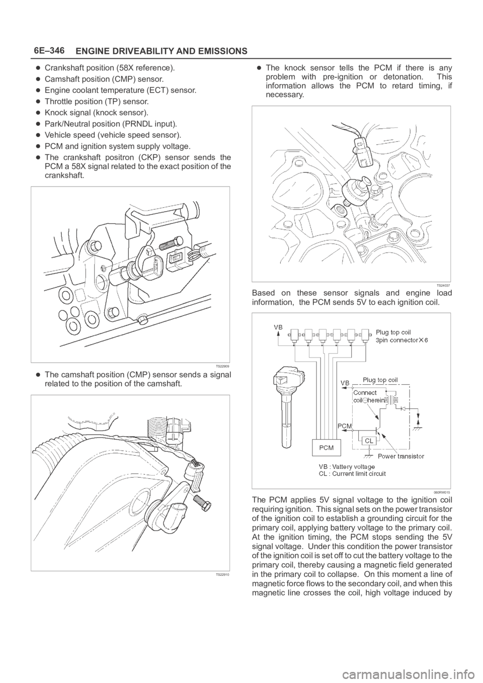
The crankshaft positron (CKP) sensor sends the
PCM a 58X signal related to the exact position of the
crankshaft.
TS22909
The camshaft position (CMP) sensor sends a signal
related to the position of the camshaft.
TS22910
The knock sensor tells the PCM if there is any
problem with pre-ignition or detonation. This
information allows the PCM to retard timing, if
necessary.
TS24037
Based on these sensor signals and engine load
information, the PCM sends 5V to each ignition coil.
060RW015
The PCM applies 5V signal voltage to the ignition coil
requiring ignition. This signal sets on the power transistor
of the ignition coil to establish a grounding circuit for the
primary coil, applying battery voltage to the primary coil.
At the ignition timing, the PCM stops sending the 5V
signal voltage. Under this condition the power transistor
of the ignition coil is set off to cut the battery voltage to the
primary coil, thereby causing a magnetic field generated
in the primary coil to collapse. On this moment a line of
magnetic force flows to the secondary coil, and when this
magnetic line crosses the coil, high voltage induced by
Page 5004 of 6000
6E–347 ENGINE DRIVEABILITY AND EMISSIONS
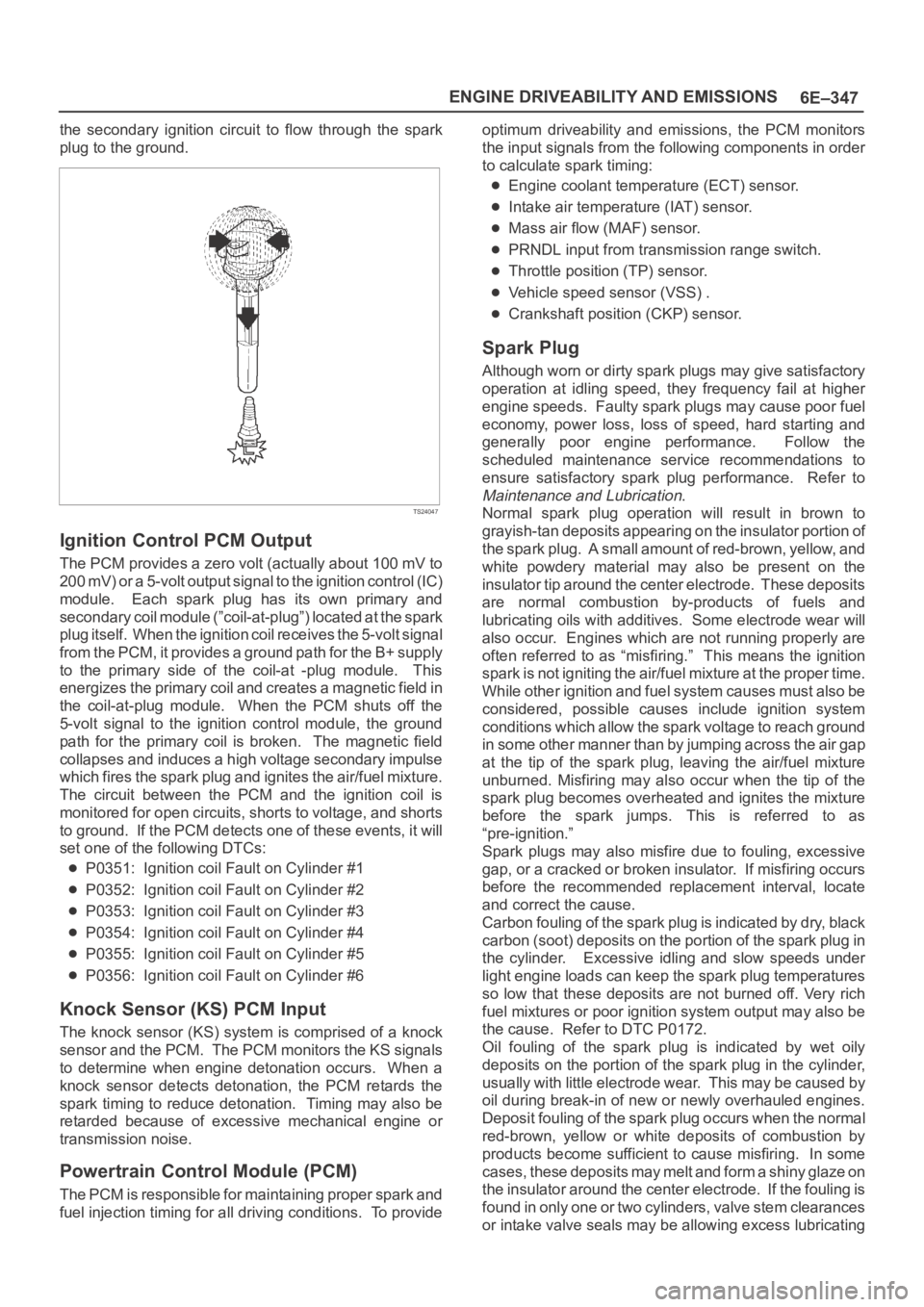
the secondary ignition circuit to flow through the spark
plug to the ground.
TS24047
Ignition Control PCM Output
The PCM provides a zero volt (actually about 100 mV to
200 mV) or a 5-volt output signal to the ignition control (IC)
module. Each spark plug has its own primary and
secondary coil module (”coil-at-plug”) located at the spark
plug itself. When the ignition coil receives the 5-volt signal
from the PCM, it provides a ground path for the B+ supply
to the primary side of the coil-at -plug module. This
energizes the primary coil and creates a magnetic field in
the coil-at-plug module. When the PCM shuts off the
5-volt signal to the ignition control module, the ground
path for the primary coil is broken. The magnetic field
collapses and induces a high voltage secondary impulse
which fires the spark plug and ignites the air/fuel mixture.
The circuit between the PCM and the ignition coil is
monitored for open circuits, shorts to voltage, and shorts
to ground. If the PCM detects one of these events, it will
set one of the following DTCs:
P0351: Ignition coil Fault on Cylinder #1
P0352: Ignition coil Fault on Cylinder #2
P0353: Ignition coil Fault on Cylinder #3
P0354: Ignition coil Fault on Cylinder #4
P0355: Ignition coil Fault on Cylinder #5
P0356: Ignition coil Fault on Cylinder #6
Knock Sensor (KS) PCM Input
The knock sensor (KS) system is comprised of a knock
sensor and the PCM. The PCM monitors the KS signals
to determine when engine detonation occurs. When a
knock sensor detects detonation, the PCM retards the
spark timing to reduce detonation. Timing may also be
retarded because of excessive mechanical engine or
transmission noise.
Powertrain Control Module (PCM)
The PCM is responsible for maintaining proper spark and
fuel injection timing for all driving conditions. To provideoptimum driveability and emissions, the PCM monitors
the input signals from the following components in order
to calculate spark timing:
Engine coolant temperature (ECT) sensor.
Intake air temperature (IAT) sensor.
Mass air flow (MAF) sensor.
PRNDL input from transmission range switch.
Throttle position (TP) sensor.
Vehicle speed sensor (VSS) .
Crankshaft position (CKP) sensor.
Spark Plug
Although worn or dirty spark plugs may give satisfactory
operation at idling speed, they frequency fail at higher
engine speeds. Faulty spark plugs may cause poor fuel
economy, power loss, loss of speed, hard starting and
generally poor engine performance. Follow the
scheduled maintenance service recommendations to
ensure satisfactory spark plug performance. Refer to
Maintenance and Lubrication.
Normal spark plug operation will result in brown to
grayish-tan deposits appearing on the insulator portion of
the spark plug. A small amount of red-brown, yellow, and
white powdery material may also be present on the
insulator tip around the center electrode. These deposits
are normal combustion by-products of fuels and
lubricating oils with additives. Some electrode wear will
also occur. Engines which are not running properly are
often referred to as “misfiring.” This means the ignition
spark is not igniting the air/fuel mixture at the proper time.
While other ignition and fuel system causes must also be
considered, possible causes include ignition system
conditions which allow the spark voltage to reach ground
in some other manner than by jumping across the air gap
at the tip of the spark plug, leaving the air/fuel mixture
unburned. Misfiring may also occur when the tip of the
spark plug becomes overheated and ignites the mixture
before the spark jumps. This is referred to as
“pre-ignition.”
Spark plugs may also misfire due to fouling, excessive
gap, or a cracked or broken insulator. If misfiring occurs
before the recommended replacement interval, locate
and correct the cause.
Carbon fouling of the spark plug is indicated by dry, black
carbon (soot) deposits on the portion of the spark plug in
the cylinder. Excessive idling and slow speeds under
light engine loads can keep the spark plug temperatures
so low that these deposits are not burned off. Very rich
fuel mixtures or poor ignition system output may also be
the cause. Refer to DTC P0172.
Oil fouling of the spark plug is indicated by wet oily
deposits on the portion of the spark plug in the cylinder,
usually with little electrode wear. This may be caused by
oil during break-in of new or newly overhauled engines.
Deposit fouling of the spark plug occurs when the normal
red-brown, yellow or white deposits of combustion by
products become sufficient to cause misfiring. In some
c a s e s , t h e s e d e p o s i t s m a y m e l t a n d f o r m a s h i n y g l a z e o n
the insulator around the center electrode. If the fouling is
found in only one or two cylinders, valve stem clearances
or intake valve seals may be allowing excess lubricating
Page 5006 of 6000
6E–349 ENGINE DRIVEABILITY AND EMISSIONS
Damage during re-gapping can happen if the gapping
tool is pushed against the center electrode or the
insulator around it, causing the insulator to crack.
When re-gapping a spark plug, make the adjustment
by bending only the ground side terminal, keeping the
tool clear of other parts.
”Heat shock” breakage in the lower insulator tip
generally occurs during several engine operating
conditions (high speeds or heavy loading) and may be
caused by over-advanced timing or low grade fuels.
Heat shock refers to a rapid increase in the tip
temperature that causes the insulator material to
crack.
Spark plugs with less than the recommended amount of
service can sometimes be cleaned and re-gapped , then
returned to service. However, if there is any doubt about
the serviceability of a spark plug, replace it. Spark plugs
with cracked or broken insulators should always be
replaced.
A/C Clutch Diagnosis
A/C Clutch Circuit Operation
A 12-volt signal is supplied to the A/C request input of the
PCM when the A/C is selected through the A/C control
switch.
The A/C compressor clutch relay is controlled through the
PCM. This allows the PCM to modify the idle air control
position prior to the A/C clutch engagement for better idle
quality. If the engine operating conditions are within their
specified calibrated acceptable ranges, the PCM will
enable the A/C compressor relay. This is done by
providing a ground path for the A/C relay coil within the
PCM. When the A/C compressor relay is enabled,
battery voltage is supplied to the compressor clutch coil.
The PCM will enable the A/C compressor clutch
whenever the engine is running and the A/C has been
requested. The PCM will not enable the A/C compressor
clutch if any of the following conditions are met:
The throttle is greater than 90%.
The engine speed is greater than 6315 RPM.
The ECT is greater than 119C (246F).
The IAT is less than 5C (41F).
The throttle is more than 80% open.
A/C Clutch Circuit Purpose
The A/C compressor operation is controlled by the
powertrain control module (PCM) for the following
reasons:
It improvises idle quality during compressor clutch
engagement.
It improvises wide open throttle (WOT) performance.
It provides A/C compressor protection from operation
with incorrect refrigerant pressures.
The A/C electrical system consists of the following
components:
The A/C control head.
The A/C refrigerant pressure switches.
The A/C compressor clutch.
The A/C compressor clutch relay.
The PCM.
A/C Request Signal
This signal tells the PCM when the A/C mode is selected
at the A/C control head. The PCM uses this to adjust the
idle speed before turning on the A/C clutch. The A/C
compressor will be inoperative if this signal is not
available to the PCM.
Refer to
A/C Clutch Circuit Diagnosis for A/C wiring
diagrams and diagnosis for A/C electrical system.
General Description (Exhaust Gas
Recirculation (EGR) System)
EGR Purpose
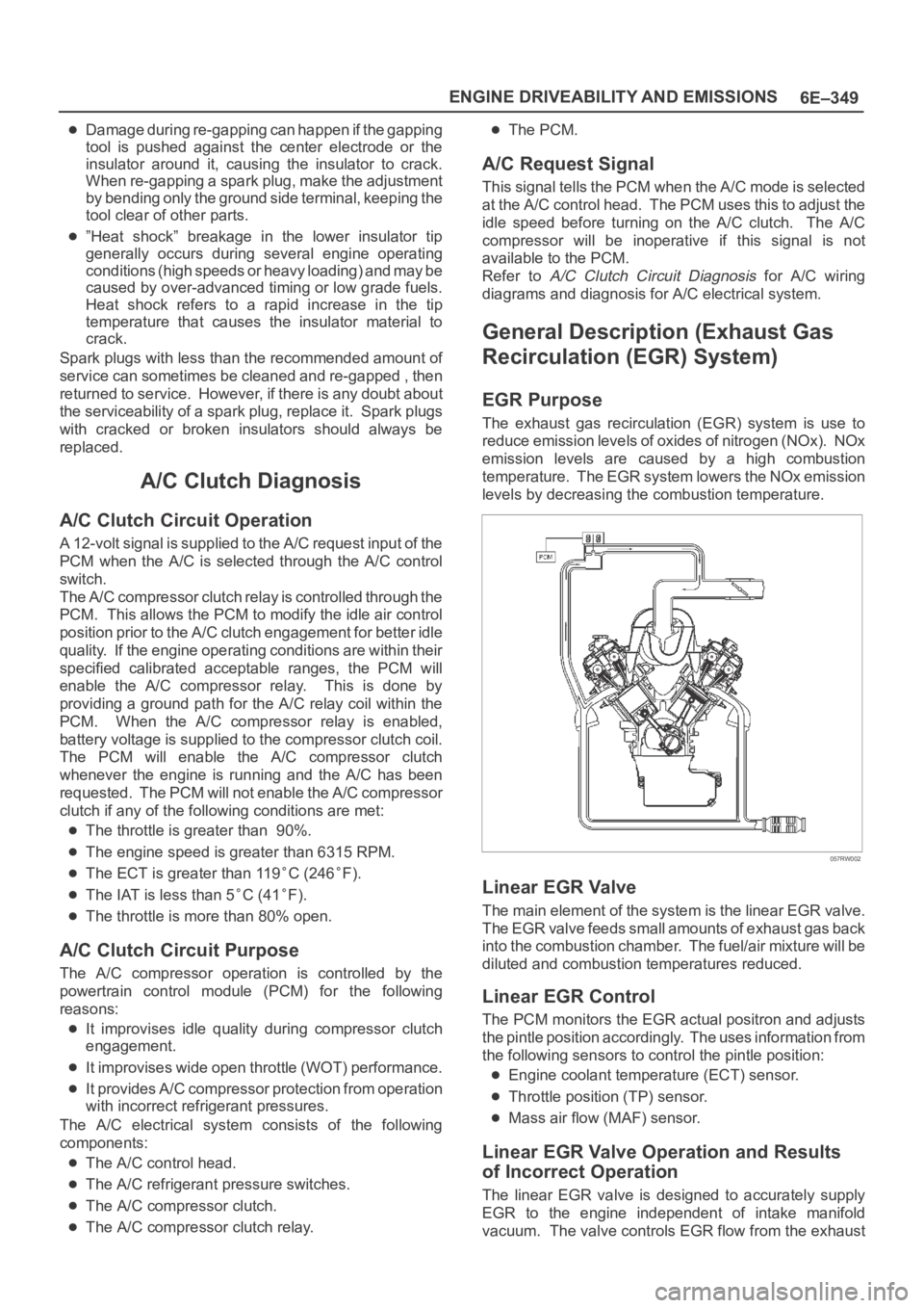
The exhaust gas recirculation (EGR) system is use to
reduce emission levels of oxides of nitrogen (NOx). NOx
emission levels are caused by a high combustion
temperature. The EGR system lowers the NOx emission
levels by decreasing the combustion temperature.
057RW002
Linear EGR Valve
The main element of the system is the linear EGR valve.
The EGR valve feeds small amounts of exhaust gas back
into the combustion chamber. The fuel/air mixture will be
diluted and combustion temperatures reduced.
Linear EGR Control
The PCM monitors the EGR actual positron and adjusts
the pintle position accordingly. The uses information from
the following sensors to control the pintle position:
Engine coolant temperature (ECT) sensor.
Throttle position (TP) sensor.
Mass air flow (MAF) sensor.
Linear EGR Valve Operation and Results
of Incorrect Operation
The linear EGR valve is designed to accurately supply
EGR to the engine independent of intake manifold
vacuum. The valve controls EGR flow from the exhaust
Page 5276 of 6000

ENGINE MECHANICAL 6A – 3
SERVICE INFORMATION
MAIN DATA AND SPECIFICATION
Engine type Diesel, four cycle water cooled inline
Camshaft type DOHC
Number of cylinders 4
Bore x stroke (mm) 95.4 x 104.9
Total piston displacement (cc) 2999
Compression ratio (to 1) 19.0
Engine weight (dry) N (kg/lb) 2492 (254/560) (A/T)
2649 (270/593) (M/T)
Engine idling speed (Reference) RPM 720
Compression pressure kpa (kg/cm
2/psi)-rpm 3000 (31/440)-200
Firing order 1–3–4–2
VALVE SYSTEM
Intake valves open at: B.T.D.C. 3°
close at: A.B.D.C. 57.6°
Exhaust valves open at: B.B.D.C. 56.5°
close at: A.T.D.C. 5°
Valve clearance at cold mm (in)
intake: 0.15 (0.006)
exhaust: 0.25 (0.01)
Oil filter Full flow and bypass combined type
Oil capacity (Original factory fill or rebuilt engine) 9.0 liters (7.9 US quarts)
Oil capacity (Service change)
with filter change 6.0 liters (6.3 US quarts)
without filter change 5.0 liters (5.3 US quarts)
Oil cooler Water cooled type
Inter cooler Air cooled type
Turbocharger method
Control method Wastegate control
Lubrication Pressurized control
Cooling method Coolant cooled
Page 5277 of 6000

6A – 4 ENGINE MECHANICAL
Engine Cooling
Starting System
Cooling system Coolant forced circulation
Radiator (2 tube in row) Tube type corrugated
Heat radiation capacity J/h (kcal/h) 318 x 10
6(76000)
Heat radiation area m
2(ft2) 15.63 (1.454)
Front area m
2(ft2) 0.309 (2.029)
Dry weight N (kg/lb) 83 (8.5/18.7)
Radiator cap
Valve opening pressure kPa (kg/cm
2psi) 93.3 – 122.7 (0.95 – 1.25/13.5 – 17.8)
Coolant capacity lit (Imp.qt./US qt.) M/T 2.5 (2.2/2.6) A/T 2.4 (2.1/2.5)
Coolant pump Centrifugal impeller type
Pulley ratio 1.2
Coolant total capacity lit (Imp.qt./US qt.) 9.3 (8.2/9.8)
Model HITACHI S14-0
Rating
Voltage V 12
Output kW 2.8
Time sec 30
Number of teeth of pinion 9
Rotating direction (as viewed from pinion) Clockwise
Weight (approx.) N(kg/lb) 49 (5.0/11)
No-load characteristics
Voltage/current V/A 11/160 or less
Speed rpm 4000 or more
Load characteristics
Voltage/current V/A 8.76/300
Torque Nꞏm(kgꞏm/lbꞏft) 7.4 (0.75/5.4) or more
Speed rpm 1700 or more
Locking characteristics
Voltage/current V/A 2.5/1100 or less
Torque Nꞏm(kgꞏm/lbꞏft) 18.6 (1.9/14) or more
Page 5283 of 6000

6A – 10 ENGINE MECHANICAL
8. Check the engine oil level and replenish to the
specified level if required.
9. Start the engine and check for oil leakage from the
main oil filter.
FUEL SYSTEM
Fuel filter
Replacement Procedure
1. Loosen the used fuel filter by turning it
counterclockwise with the filter wrench.
Filter Wrench : 5-8840-0203-0
2. Clean the filter cover fitting faces.
This will allow the new fuel filter to seat properly.
3. Apply a light coat of engine oil to the O-ring.
4. Turn the fuel filter until the sealing face comes in
contact with the O-ring.
5. Turn the fuel filter with a filter wrench 2/3 of a turn
until sealed.
Filter Wrench: 5-8840-0203-0Legend
(1) Priming pump
6. Operate the priming pump until the air is discharged
completely from fuel system.
NOTE: The use of an Isuzu genuine fuel filter is
strongly recommended.
COOLING SYSTEM
Coolant Level
Check the coolant level and replenish the radiator
reserve tank as necessary.
If the coolant level falls below the “‘MIN” line, carefully
check the cooling system for leakage. Then add
enough coolant to bring the level up to the “MAX” line.
NOTE: Do not overfill the reserve tank.
012RW112
012RW078
1
012RW111
012RW080
Page 5284 of 6000
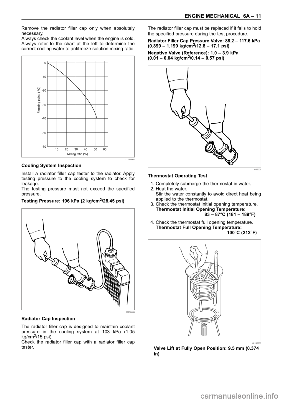
ENGINE MECHANICAL 6A – 11
Remove the radiator filler cap only when absolutely
necessary.
Always check the coolant level when the engine is cold.
Always refer to the chart at the left to determine the
correct cooling water to antifreeze solution mixing ratio.
Cooling System Inspection
Install a radiator filler cap tester to the radiator. Apply
testing pressure to the cooling system to check for
leakage.
The testing pressure must not exceed the specified
pressure.
Testing Pressure: 196 kPa (2 kg/cm
2/28.45 psi)
Radiator Cap Inspection
The radiator filler cap is designed to maintain coolant
pressure in the cooling system at 103 kPa (1.05
kg/cm
2/15 psi).
Check the radiator filler cap with a radiator filler cap
tester.The radiator filler cap must be replaced if it fails to hold
the specified pressure during the test procedure.
Radiator Filler Cap Pressure Valve: 88.2 – 117.6 kPa
(0.899 – 1.199 kg/cm
2/12.8 – 17.1 psi)
Negative Valve (Reference): 1.0 – 3.9 kPa
(0.01 – 0.04 kg/cm
2/0.14 – 0.57 psi)
Thermostat Operating Test
1. Completely submerge the thermostat in water.
2. Heat the water.
Stir the water constantly to avoid direct heat being
applied to the thermostat.
3. Check the thermostat initial opening temperature.
Thermostat Initial Opening Temperature:
83 – 87°C (181 – 189°F)
4. Check the thermostat full opening temperature.
Thermostat Full Opening Temperature:
100°C (212°F)
Valve Lift at Fully Open Position: 9.5 mm (0.374
in)0
-10
-20
-30
-40
-50
-60
10 20 30
Mixing ratio (%)
Freezing point (
C)
40 50 60
111RW002
110RS005
110RS006
031RS003