Page 4513 of 6000
6A–17
ENGINE MECHANICAL
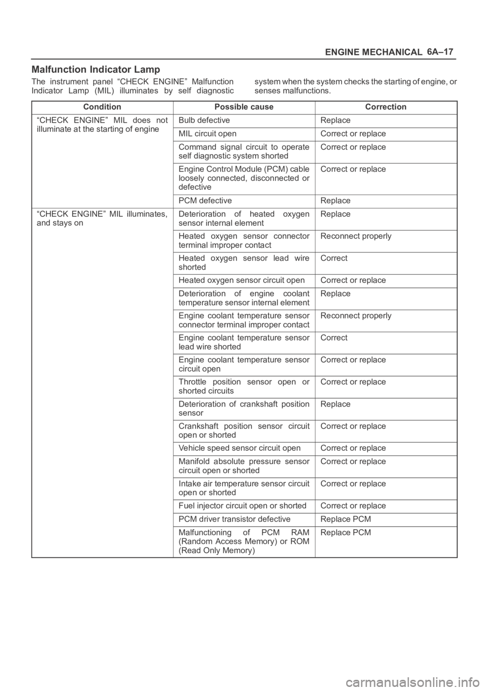
Malfunction Indicator Lamp
The instrument panel “CHECK ENGINE” Malfunction
Indicator Lamp (MIL) illuminates by self diagnosticsystem when the system checks the starting of engine, or
senses malfunctions.
Condition
Possible causeCorrection
“CHECK ENGINE” MIL does not
illuminate at the starting of engine
Bulb defectiveReplace
illuminate at the starting of engineMIL circuit openCorrect or replace
Command signal circuit to operate
self diagnostic system shortedCorrect or replace
Engine Control Module (PCM) cable
loosely connected, disconnected or
defectiveCorrect or replace
PCM defectiveReplace
“CHECK ENGINE” MIL illuminates,
and stays onDeterioration of heated oxygen
sensor internal elementReplace
Heated oxygen sensor connector
terminal improper contactReconnect properly
Heated oxygen sensor lead wire
shortedCorrect
Heated oxygen sensor circuit openCorrect or replace
Deterioration of engine coolant
temperature sensor internal elementReplace
Engine coolant temperature sensor
connector terminal improper contactReconnect properly
Engine coolant temperature sensor
lead wire shortedCorrect
Engine coolant temperature sensor
circuit openCorrect or replace
Throttle position sensor open or
shorted circuitsCorrect or replace
Deterioration of crankshaft position
sensorReplace
Crankshaft position sensor circuit
open or shortedCorrect or replace
Vehicle speed sensor circuit openCorrect or replace
Manifold absolute pressure sensor
circuit open or shortedCorrect or replace
Intake air temperature sensor circuit
open or shortedCorrect or replace
Fuel injector circuit open or shortedCorrect or replace
PCM driver transistor defectiveReplace PCM
Malfunctioning of PCM RAM
(Random Access Memory) or ROM
(Read Only Memory)Replace PCM
Page 4514 of 6000
6A–18
ENGINE MECHANICAL
Cylinder Head Cover LH
Removal
1. Disconnect battery ground cable.
2. Drain engine coolant from faucet bottom of radiator.
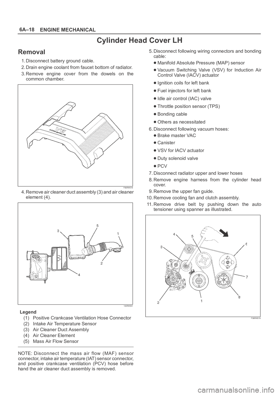
3. Remove engine cover from the dowels on the
common chamber.
F06RW018
4. Remove air cleaner duct assembly (3) and air cleaner
element (4).
130RW001
Legend
(1) Positive Crankcase Ventilation Hose Connector
(2) Intake Air Temperature Sensor
(3) Air Cleaner Duct Assembly
(4) Air Cleaner Element
(5) Mass Air Flow Sensor
NOTE: Disconnect the mass air flow (MAF) sensor
connector, intake air temperature (IAT) sensor connector,
and positive crankcase ventilation (PCV) hose before
hand the air cleaner duct assembly is removed.5. Disconnect following wiring connectors and bonding
cable:
Manifold Absolute Pressure (MAP) sensor
Vacuum Switching Valve (VSV) for Induction Air
Control Valve (IACV) actuator
Ignition coils for left bank
Fuel injectors for left bank
Idle air control (IAC) valve
Throttle position sensor (TPS)
Bonding cable
Others as necessitated
6. Disconnect following vacuum hoses:
Brake master VAC
Canister
VSV for IACV actuator
Duty solenoid valve
PCV
7. Disconnect radiator upper and lower hoses
8. Remove engine harness from the cylinder head
cover.
9. Remove the upper fan guide.
10. Remove cooling fan and clutch assembly.
11. Remove drive belt by pushing down the auto
tensioner using spanner as illustrated.
F06RW019
Page 4517 of 6000
6A–21
ENGINE MECHANICAL
Cylinder Head Cover RH
Removal
1. Disconnect battery ground cable.
2. Remove battery from the vehicle.
3. Drain engine coolant from faucet bottom of radiator.
4. Remove engine cover from the dowels on the
common chamber.
F06RW018
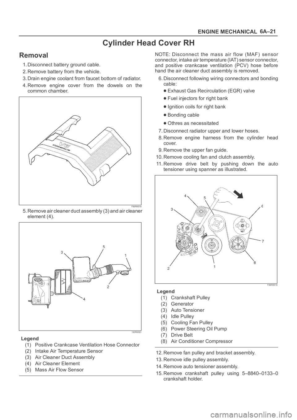
5. Remove air cleaner duct assembly (3) and air cleaner
element (4).
130RW001
Legend
(1) Positive Crankcase Ventilation Hose Connector
(2) Intake Air Temperature Sensor
(3) Air Cleaner Duct Assembly
(4) Air Cleaner Element
(5) Mass Air Flow Sensor
NOTE: Disconnect the mass air flow (MAF) sensor
connector, intake air temperature (IAT) sensor connector,
and positive crankcase ventilation (PCV) hose before
hand the air cleaner duct assembly is removed.
6. Disconnect following wiring connectors and bonding
cable:
Exhaust Gas Recirculation (EGR) valve
Fuel injectors for right bank
Ignition coils for right bank
Bonding cable
Othres as necessitated
7. Disconnect radiator upper and lower hoses.
8. Remove engine harness from the cylinder head
cover.
9. Remove the upper fan guide.
10. Remove cooling fan and clutch assembly.
11. Remove drive belt by pushing down the auto
tensioner using spanner as illustrated.
F06RW019
Legend
(1) Crankshaft Pulley
(2) Generator
(3) Auto Tensioner
(4) Idle Pulley
(5) Cooling Fan Pulley
(6) Power Steering Oil Pump
(7) Drive Belt
(8) Air Conditioner Compressor
12. Remove fan pulley and bracket assembly.
13. Remove idle pulley assembly.
14. Remove auto tensioner assembly.
15. Remove crankshaft pulley using 5–8840–0133–0
crankshaft holder.
Page 4596 of 6000
ENGINE COOLING6B–3
Thermostat
The thermostat is a wax pellet type with a air hole(1) and is
installed in the thermostat housing.
031RW002
Radiator
The radiator is a tube type with corrugated fins. In order to
raise the boiling point of the coolant, the radiator is fitted
with a cap in which the valve is operated at 88.2
117.6
kPa (12.8
1 7 . 0 p s i ) p r e s s u r e . ( N o o i l c o o l e r p r o v i d e d f o r
M/T)
110RS001
Anti Freeze Solution
Relation between the mixing ratio and freezing
temperature of the EC varies with the ratio of
anti–freeze solution in water. Proper mixing ratio can
be determined by referring to the chart. Supplemental
inhibitors or additives claiming to increase cooling
capability that have not been specifically approved by
Isuzu are not recommended for addition to the cooling
system.
Calculating mixing ratio
F06RW005
Page 4597 of 6000
6B–4
ENGINE COOLING
NOTE: Antifreeze solution + Water = Total cooling
system capacity.
Total Cooling System Capacity
M/T 8.8Lit (2.32Us gal)
A/T 8.4Lit (2.22Us gal)
B06RW002
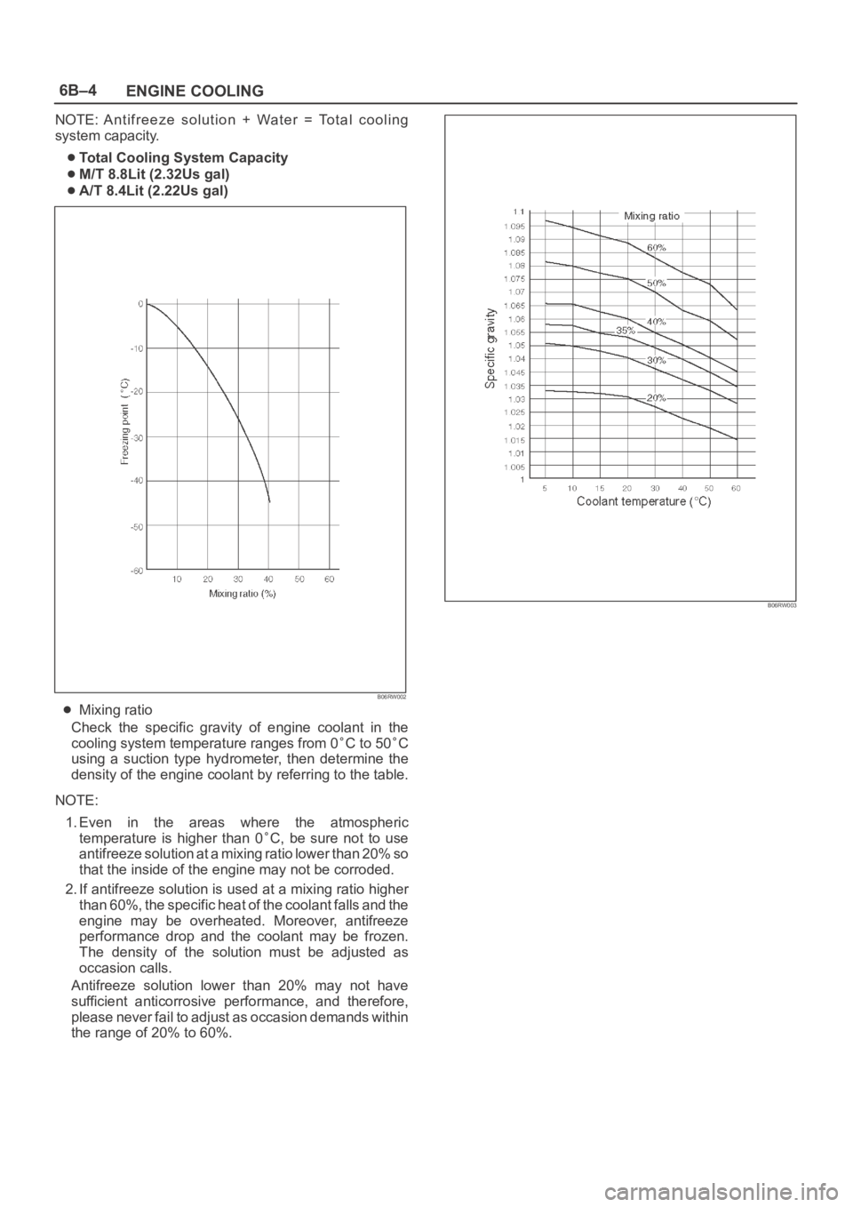
Mixing ratio
Check the specific gravity of engine coolant in the
cooling system temperature ranges from 0
C to 50C
using a suction type hydrometer, then determine the
density of the engine coolant by referring to the table.
NOTE:
1. Even in the areas where the atmospheric
temperature is higher than 0
C, be sure not to use
antifreeze solution at a mixing ratio lower than 20% so
that the inside of the engine may not be corroded.
2. If antifreeze solution is used at a mixing ratio higher
than 60%, the specific heat of the coolant falls and the
engine may be overheated. Moreover, antifreeze
performance drop and the coolant may be frozen.
The density of the solution must be adjusted as
occasion calls.
Antifreeze solution lower than 20% may not have
sufficient anticorrosive performance, and therefore,
please never fail to adjust as occasion demands within
the range of 20% to 60%.
B06RW003
Page 4598 of 6000
ENGINE COOLING6B–5
Diagnosis
Engine Cooling Trouble
ConditionPossible causeCorrection
Engine overheatingLow Engine Coolant levelReplenish
Incorrect fan installedReplace
Thermo meter unit faultyReplace
Faulty thermostatReplace
Faulty Engine Coolant temperature
sensorRepair or replace
Clogged radiatorClean or replace
Faulty radiator capReplace
Low engine oil level or use of
improper engine oilReplenish or change oil
Clogged exhaust systemClean exhaust system or replace
faulty parts
Faulty Throttle Position sensorReplace throttle valve assembly
Open or shorted Throttle Position
sensor circuitRepair or replace
Damaged cylinder head gasketReplace
Engine overcoolingFaulty thermostatReplace
Engine slow to warm–upFaulty thermostatReplace
Thermo unit faultyReplace
Page 4601 of 6000
6B–8
ENGINE COOLING
3. Idle pulley
Install idle pulley and tighten bolt to the specified
torque.
Torque: 52 Nꞏm (5.3 Kgꞏm/38 lb ft)4. Timing beltInstall timing belt. Refer to timing belt installation
step in “Timing Belt” in this manual.
5. Connect radiator inlet hose and replenish EC.
6. Connect battery ground cable.
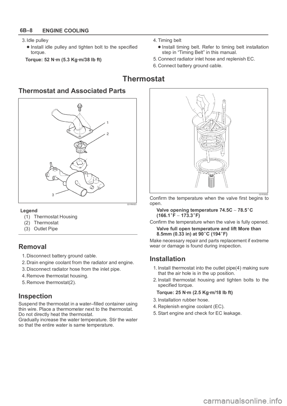
Thermostat
Thermostat and Associated Parts
031RW001
Legend
(1) Thermostat Housing
(2) Thermostat
(3) Outlet Pipe
Removal
1. Disconnect battery ground cable.
2. Drain engine coolant from the radiator and engine.
3. Disconnect radiator hose from the inlet pipe.
4. Remove thermostat housing.
5. Remove thermostat(2).
Inspection
Suspend the thermostat in a water–filled container using
thin wire. Place a thermometer next to the thermostat.
Do not directly heat the thermostat.
Gradually increase the water temperature. Stir the water
so that the entire water is same temperature.
031RS003Confirm the temperature when the valve first begins to
open.
Valve opening temperature 74.5C
78.5C
(166.1
F 173.3F)
Confirm the temperature when the valve is fully opened.
Valve full open temperature and lift More than
8.5mm (0.33 in) at 90
C (194F)
Make necessary repair and parts replacement if extreme
wear or damage is found during inspection.
Installation
1. Install thermostat into the outlet pipe(4) making sure
that the air hole is in the up position.
2. Install thermostat housing and tighten bolts to the
specified torque.
Torque: 25 Nꞏm (2.5 Kgꞏm/18 lb ft)
3. Installation rubber hose.
4. Replenish engine coolant (EC).
5. Start engine and check for EC leakage.
Page 4604 of 6000
ENGINE COOLING6B–11
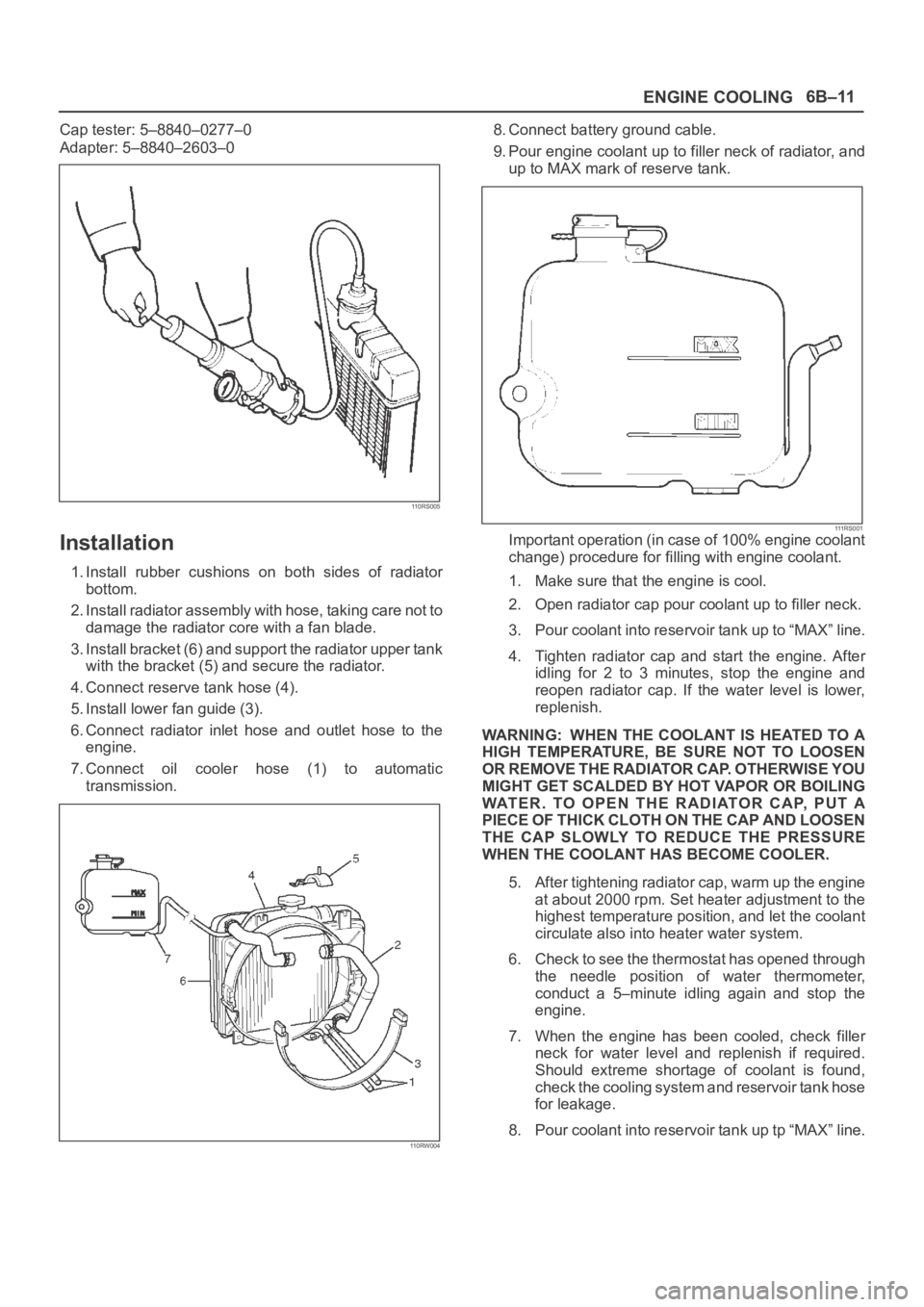
Cap tester: 5–8840–0277–0
Adapter: 5–8840–2603–0
110RS005
Installation
1. Install rubber cushions on both sides of radiator
bottom.
2. Install radiator assembly with hose, taking care not to
damage the radiator core with a fan blade.
3. Install bracket (6) and support the radiator upper tank
with the bracket (5) and secure the radiator.
4. Connect reserve tank hose (4).
5. Install lower fan guide (3).
6. Connect radiator inlet hose and outlet hose to the
engine.
7. Connect oil cooler hose (1) to automatic
transmission.
110RW004
8. Connect battery ground cable.
9. Pour engine coolant up to filler neck of radiator, and
up to MAX mark of reserve tank.
111 R S 0 0 1Important operation (in case of 100% engine coolant
change) procedure for filling with engine coolant.
1. Make sure that the engine is cool.
2. Open radiator cap pour coolant up to filler neck.
3. Pour coolant into reservoir tank up to “MAX” line.
4. Tighten radiator cap and start the engine. After
idling for 2 to 3 minutes, stop the engine and
reopen radiator cap. If the water level is lower,
replenish.
WARNING: WHEN THE COOLANT IS HEATED TO A
HIGH TEMPERATURE, BE SURE NOT TO LOOSEN
OR REMOVE THE RADIATOR CAP. OTHERWISE YOU
MIGHT GET SCALDED BY HOT VAPOR OR BOILING
WATER. TO OPEN THE RADIATOR CAP, PUT A
PIECE OF THICK CLOTH ON THE CAP AND LOOSEN
THE CAP SLOWLY TO REDUCE THE PRESSURE
WHEN THE COOLANT HAS BECOME COOLER.
5. After tightening radiator cap, warm up the engine
at about 2000 rpm. Set heater adjustment to the
highest temperature position, and let the coolant
circulate also into heater water system.
6. Check to see the thermostat has opened through
the needle position of water thermometer,
conduct a 5–minute idling again and stop the
engine.
7. When the engine has been cooled, check filler
neck for water level and replenish if required.
Should extreme shortage of coolant is found,
check the cooling system and reservoir tank hose
for leakage.
8. Pour coolant into reservoir tank up tp “MAX” line.