1998 OPEL FRONTERA check engine
[x] Cancel search: check enginePage 5712 of 6000

7A–23 AUTOMATIC TRANSMISSION (4L30–E)
Stall Test
The stall test allows you to check the transmission for
internal abrasion and the one way clutch for slippage.
Torque converter performance can also be evaluated.
The stall test results together with the road test results will
identify transmission components requiring servicing or
adjustment.
Stall Test Procedure:
1. Check the level of the engine coolant, the engine oil,
and the automatic transmission fluid. Replenish if
necessary.
2. Block the wheels and set the parking brake.
3. Connect a tachometer to the engine.
4. Start the engine and allow it to idle until the engine
coolant temperature reaches 70 – 80
C (158 –
176
F).
5. Hold the brake pedal down as far as it will go.
6. Place the selector in the “D” range.
7. Gradually push the accelerator pedal to the floor.
The throttle valve will be fully open.
Note the engine speed at which the tachometer
needle stabilizes.
Stall Speed : 2,100
150 rpm
NOTE: Do not continuously run this test longer than 5
seconds.
8. Release the accelerator pedal.
9. Place the selector in the “N” range.
10. Run the engine at 1,200 rpm for one minute.
This will cool the transmission fluid.
11. Repeat Steps 7 – 10 for the “3”, “2”, “L” and “R”
ranges.
Line Pressure Test
The line pressure test checks oil pump and control valve
pressure regulator valve function. It will also detect oil
leakage.
Line Pressure Test Procedure:
1. Check the level of the engine coolant, the engine oil,
and the automatic transmission fluid.
Replenish if required.
2. Block the wheels and set the parking brake.
3. Remove the pressure detection plug at the left side of
the transmission case.
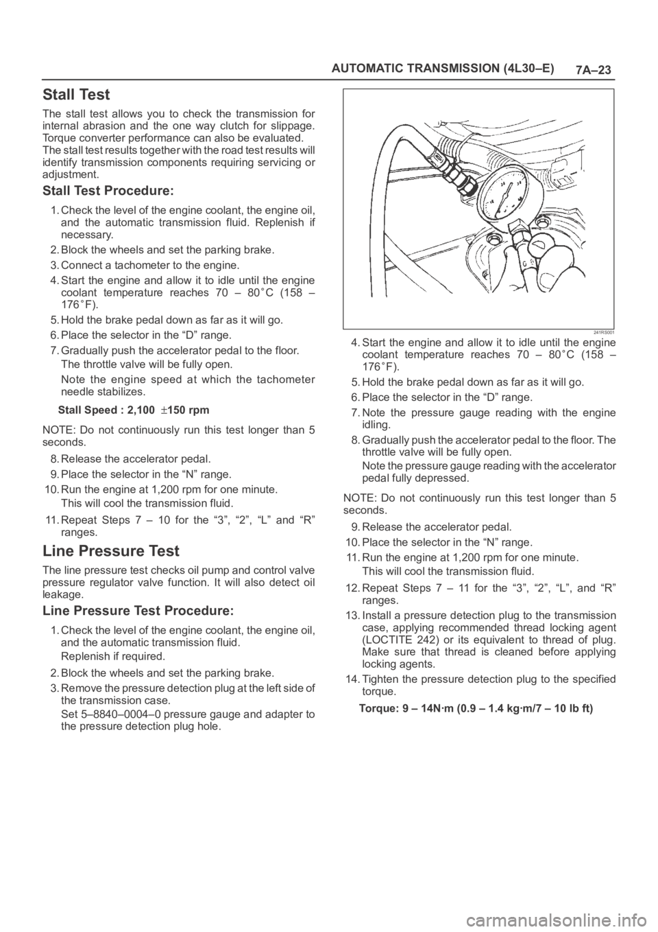
Set 5–8840–0004–0 pressure gauge and adapter to
the pressure detection plug hole.
241RS001
4. Start the engine and allow it to idle until the engine
coolant temperature reaches 70 – 80
C (158 –
176
F).
5. Hold the brake pedal down as far as it will go.
6. Place the selector in the “D” range.
7. Note the pressure gauge reading with the engine
idling.
8. Gradually push the accelerator pedal to the floor. The
throttle valve will be fully open.
Note the pressure gauge reading with the accelerator
pedal fully depressed.
NOTE: Do not continuously run this test longer than 5
seconds.
9. Release the accelerator pedal.
10. Place the selector in the “N” range.
11. Run the engine at 1,200 rpm for one minute.
This will cool the transmission fluid.
12. Repeat Steps 7 – 11 for the “3”, “2”, “L”, and “R”
ranges.
13. Install a pressure detection plug to the transmission
case, applying recommended thread locking agent
(LOCTITE 242) or its equivalent to thread of plug.
Make sure that thread is cleaned before applying
locking agents.
14. Tighten the pressure detection plug to the specified
torque.
Torque:9–14Nꞏm(0.9–1.4kgꞏm/7–10lbft)
Page 5718 of 6000

7A–29 AUTOMATIC TRANSMISSION (4L30–E)
Changing Transmission Fluid
There is no need to change the transmission fluid unless
the transmission is used under one or more of the
following heavy duty conditions.
A. Repeated short trips
B. Driving on rough roads
C. Driving on dusty roads
D. Towing a trailer
If the vehicle is used under these conditions, change the
fluid every 20,000 miles (32,000 km).
More over, the remaining life percentage of ATF can be
estimated by using Tech 2 as an auxiliary tool to judge the
right time for ATF replacement.
The remaining life percentage is calculated from ATF’S
heat history. When it is close to 0%, ATF replacement is
recommended.
1. Place a large drain pan under the oil pan.
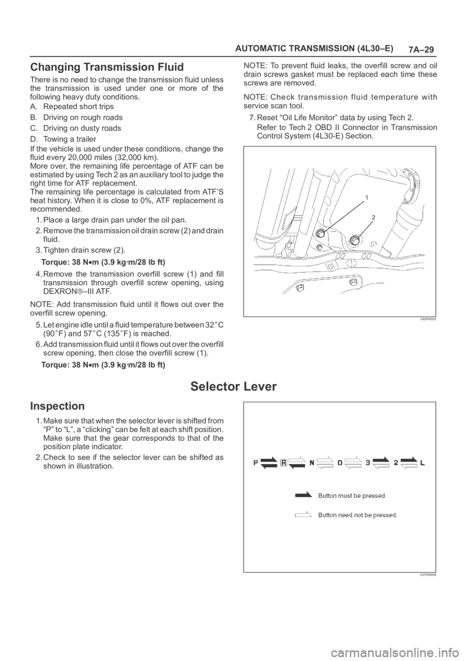
2. Remove the transmission oil drain screw (2) and drain
fluid.
3. Tighten drain screw (2).
Torque: 38 N
m (3.9 kgꞏm/28 lb ft)
4. Remove the transmission overfill screw (1) and fill
transmission through overfill screw opening, using
DEXRON
–III ATF.
NOTE: Add transmission fluid until it flows out over the
overfill screw opening.
5. Let engine idle until a fluid temperature between 32
C
(90
F) and 57C (135F) is reached.
6. Add transmission fluid until it flows out over the overfill
screw opening, then close the overfill screw (1).
Torque: 38 N
m (3.9 kgꞏm/28 lb ft)NOTE: To prevent fluid leaks, the overfill screw and oil
drain screws gasket must be replaced each time these
screws are removed.
NOTE: Check transmission fluid temperature with
service scan tool.
7. Reset “Oil Life Monitor” data by using Tech 2.
Refer to Tech 2 OBD II Connector in Transmission
Control System (4L30-E) Section.
242RW003
Selector Lever
Inspection
1. Make sure that when the selector lever is shifted from
“P” to “L”, a “clicking” can be felt at each shift position.
Make sure that the gear corresponds to that of the
position plate indicator.
2. Check to see if the selector lever can be shifted as
shown in illustration.
C07RW009
Page 5790 of 6000

AUTOMATIC TRANSMISSION (AW30-40LE) 7A–9
MAJOR INPUT/OUTPUT COMPONENTS
Component Function
Input
Vehicle speed sensor (Speedometer) Detects the vehicle speed (Back-up sensor of output
revolution sensor).
Output revolution sensor (Transmission) Detects the vehicle speed.
Input revolution sensor (Transmission) Detects the input revolution (O/D direct clutch drum
revolution).
Engine revolution sensor Detects the engine revolution.
Throttle position sensor Detects the throttle opening rate.
Neutral start switch Detects the select lever position.
Pattern select switch Detects whether the driver has selected "NORMAL",
"POWER", or "WINTER" mode.
Overdrive off switch Detects whether the driver has selected O/D.
Brake lamp switch Detects whether the driver has pressed the brake pedal or
not.
Oil temperature sensor Detects the oil temperature.
Diagnostic star t switch Star ts self-diagnosis and displays a code for faulty part if
any.
Input/Output
Data link connector When connected with Tech2 or tester, can communicate
the data for function check, etc.
Output
Shift solenoid S1, S2 Selects shift point and gear position suited to the vehicle
running condition on the basis of TCM output.
Lock-up control solenoid SL Control the lock-up clutch suited to the vehicle running
condition on the basis of TCM output.
Pressure control solenoid STH Adjusts throttle pressure by energizing current of linear
pressure control solenoid to prevent the shift shock and to
obtain shift smoothly.
"CHECK TRANS" lamp When trouble has occurred to throttle position sensor,
vehicle speed sensor, or solenoid, "CHECK TRANS" lamp
is blinked to warn the driver. If also displays the trouble
code.
A/T OIL TEMP warning lamp Lights when ATF oil temperature rises. (Turned on at
greater than 146
C . Turned off at less than 126C.
Power mode lamp Informs the driver whether the vehicle is in power mode or
not.
Winter mode lamp Informs the driver whether the vehicle is in winter mode or
not.
Computer
Transmission Control Module (TCM) Based on the signal from each switch and sensors, judges
necessary shift point and lock-up operation, and send
signal to each solenoid.
Page 5795 of 6000

7A–14 AUTOMATIC TRANSMISSION (AW30-40LE)
821RY00012
F07LV002
740RY00013
740RY00014
SELF-DIAGNOSIS
Warning to the driver
• When trouble has occurred to throttle position sensor, output
revolution sensor, input revolution sensor, neutral star t
switch, engine revolution signal, speed meter signal, or
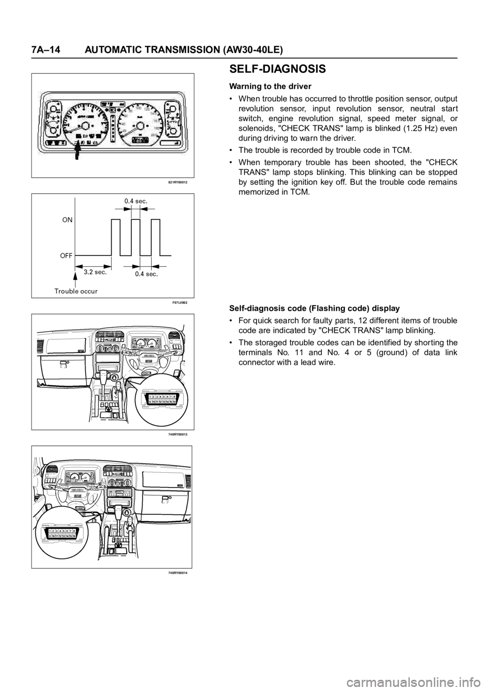
solenoids, "CHECK TRANS" lamp is blinked (1.25 Hz) even
during driving to warn the driver.
• The trouble is recorded by trouble code in TCM.
• When temporary trouble has been shooted, the "CHECK
TRANS" lamp stops blinking. This blinking can be stopped
by setting the ignition key off. But the trouble code remains
memorized in TCM.
Self-diagnosis code (Flashing code) display
• For quick search for faulty parts, 12 different items of trouble
code are indicated by "CHECK TRANS" lamp blinking.
• The storaged trouble codes can be identified by shor ting the
terminals No. 11 and No. 4 or 5 (ground) of data link
connector with a lead wire.
Page 5801 of 6000

7A–20 AUTOMATIC TRANSMISSION (AW30-40LE)
Once the test vehicle has been identified an “Application
(Power train) Menu" screen appears. Please select the
appropriate application.
The following table shows, which functions are used for
the available equipment versions.
Diagnostic Trouble Codes
The purpose of the “Diagnostic Trouble Codes" mode is
to display stored TCM trouble codes.
When “Diagnostic Trouble Codes" is selected an
“Application Menu" screen appears.
Clear DTC Information
The purpose of the “Clear DTC Information" mode is to
command the clearing of stored TCM trouble codes.
When “Clear DTC Information" is selected, a “Clear
DTC Information", warning screen appears. This screen
informs you that by cleaning DTC's, “all stored DTC
information in controller will be erased".
Do you want to clear DTC's (Yes/No).
Press either the Yes or No key when answering.
After clearing codes, confirm system operation by test
driving the vehicle.
Allow the vehicle to shift through all four forward gears in
a manner which attempts to repeat the failure condition.
NOTE: When the trouble has not been repaired and thetrouble code cannot be erased, check the vehicle again.
DTC Information
When “DTC Information" is selected, an “Application
Menu" appears with a list of DTC information function
keys addressing DTC specifics and their origins.
Function key selections may vary for particular vehicle
and/or system.
Data Display
The purpose of the “Data Display" mode is to
continuously monitor data parameters.
The current actual values of all impor tant sensors and
signals in the system are display through F1 mode.
When “Data Display" is selected an “Application Menu"
appears.
See “TRANSMISSION DATA" and “TCC DATA” on next
page.
Snapshot
When “Snapshot" is selected an “Application Menu"
appears.
When “Transmission Snapshot" application is selected
from the “Application Menu", a “Snapshot Menu"
appears, displaying several options. “Snapshot" options
may vary from one system to another.
“Snapshot" allows a recording of all vehicle parameters.
There parameters may then be replayed at a future
point in time.
This action allows you to focus on making the condition
occur, rather than trying to view all of the data in
anticipation of the fault. The snapshot will collect
parameter information around a trigger point that you
select.
When a snapshot is taken. It is recorded onto the
PCMCIA memory card. When the Tech2 is powered
down. Snapshots are not lost.
Actuator Tests
The purpose of “Actuator Tests" mode is to check for
correct operation of electronic system actuators.
Lamps
You can operate the lamps by pressing the ON and OFF
buttons.
Preconditions: P or N position
Solenoid
Solenoid S1(1-2/3-4), S2(2-3) and TCC Solenoid
(Torque Converter Clutch)
You can operate the solenoids by pressing the ON and
OFF buttons.
Preconditions: P or N position, no vehicle speed, no
engine speed
Pressure Control Solenoid (PCS)
You can operate the PC Solenoid by pressing the ON
and OFF buttons. ON will command a maximum current
of 1000 mA and OFF a minimum of 200 mA.
Preconditions: P or N position, no vehicle speed, engine
running F0: Diagnostic Trouble Codes
F0: Read DTC Info Ordered By Priority
F1: Clear DTC Information
F2: DTC Information
F0: History
F1: MIL SVS or Message Requested
F2: Last Test Failed
F3: Test Failed Since Code Cleared
F4: Not Ran Since Code Cleared
F5: Failed This Ignition
F1: Data Display
F0: Transmission Data
F1: TCC Data
F2: Snapshot
F3: Actuator Tests
F0: Lamps
F0: Check Light Test
F1: Power Lamp Test
F2: Winter Lamp Test
F3: AT Oil Temperature Lamp Test
F1: Solenoids
F0: Solenoid 2-3 Test
F1: Solenoid 1-2/3-4 Test
F2: TCC Solenoid Test
F3: Pressure Control Solenoid (PCS)
Page 5802 of 6000

AUTOMATIC TRANSMISSION (AW30-40LE) 7A–21
TRANSMISSION DATA
Item Unit Enigne running at idle
Current Gear1
Lock Up Inactive, Active Inactive
Selector PositionPar k
AT Output Speed (Automatic Transmission) RPM 0 RPM
Output Speed (Meter Signal Side) RPM 0 RPM
AT Input Speed (Automatic Transmission) RPM 0 RPM
Engine Speed RPM 695
745 RPM
Vehicle Speed (Output Side) km/h 0 km/h
Throttle Position % 0 %
Throttle Position Sensor V 0.25
0.45V
AT Oil Temperature (Automatic Transmission)
C, F70 80C (158 176F)
Shift Pattern
Desired PCS Pressure (Pressure Control Solenoid) kPa
PCS Desired Current (Pressure Control Solenoid) mA
PCS Actual Current (Pressure Control Solenoid) mA
Overdrive Off Switch Off, On
Brake Switch Open 0V, Closed 12V Closed 12V
Winter Switch Open, Closed 0V Open
Power Switch Open, Closed 0V Open
Diagnostic Request Open, Closed Open
Winter Lamp Inactive 12V, Active 0V Inactive 12V
Power Lamp Inactive 12V, Active 0V Inactive 12V
Check Light Inactive 12V, Active 0V Inactive 12V
AT Oil Temperature Lamp (Automatic Transmission) Inactive 12V, Active 0V Inactive 12V
Solenoid 2-3 Inactive 0V, Active 12V Inactive 0V
Solenoid 1-2/3-4 Inactive 0V, Active 12V Active 12V
TCC Solenoid (Torque Conver ter Clutch) Inactive 0V, Active 12V Inactive 0V
Page 5806 of 6000

AUTOMATIC TRANSMISSION (AW30-40LE) 7A–25
DIAGNOSTIC TROUBLE CODES (DTC) CHECK
DTC
NUMBERFLASHING
CODEDESCRIPTION
P0120 21 ANALOG THROTTLE SIGNAL FAILURE (VTH)
P0502 24 SPEED METER SENSOR FAILURE (SP1)
P0705 17 GEAR SELECTOR FAILURE (PRND2L)
P0710 16 OIL TEMPERATURE SENSOR FAILURE (OT2)
P0717 14 INPUT REVOLUTION SENSOR FAILURE (NC0)
P0722 11 OUTPUT REVOLUTION SENSOR FAILURE (SP2)
P0727 13 ENGINE REVOLUTION SIGNAL FAILURE (NE)
P0743 33 TORQUE CONVERTER CLUTCH CONTROL LOCK-UP (ON/OFF) SOLENOID
FA I L U R E ( S L )
P0748 35 PRESSURE CONTROL SOLENOID FAILURE (STH)
P0753 31 SOLENOID 1 FAILURE (S1)
P0758 32 SOLENOID 2 FAILURE (S2)
P1121 23 ANALOG THROTTLE SIGNAL FAILURE (VREF, VGND)
Page 5807 of 6000

7A–26 AUTOMATIC TRANSMISSION (AW30-40LE)
DTC P0120 (FLASHING CODE 21) ANALOG THROTTLE SIGNAL FAILURE (VTH)
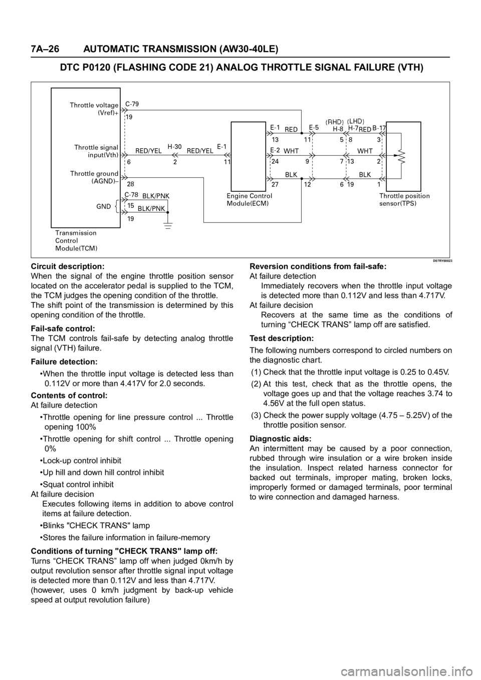
D07RY00023Circuit description:
When the signal of the engine throttle position sensor
located on the accelerator pedal is supplied to the TCM,
the TCM judges the opening condition of the throttle.
The shift point of the transmission is determined by this
opening condition of the throttle.
Fail-safe control:
The TCM controls fail-safe by detecting analog throttle
signal (VTH) failure.
Failure detection:
•When the throttle input voltage is detected less than
0.112V or more than 4.417V for 2.0 seconds.
Contents of control:
At failure detection
•Throttle opening for line pressure control ... Throttle
opening 100%
•Throttle opening for shift control ... Throttle opening
0%
•Lock-up control inhibit
•Up hill and down hill control inhibit
•Squat control inhibit
At failure decision
Executes following items in addition to above control
items at failure detection.
•Blinks "CHECK TRANS" lamp
•Stores the failure information in failure-memory
Conditions of turning "CHECK TRANS" lamp off:
Turns “CHECK TRANS” lamp off when judged 0km/h by
output revolution sensor after throttle signal input voltage
is detected more than 0.112V and less than 4.717V.
(however, uses 0 km/h judgment by back-up vehicle
speed at output revolution failure)Reversion conditions from fail-safe:
At failure detection
Immediately recovers when the throttle input voltage
is detected more than 0.112V and less than 4.717V.
At failure decision
Recovers at the same time as the conditions of
turning “CHECK TRANS” lamp off are satisfied.
Test description:
The following numbers correspond to circled numbers on
the diagnostic char t.
(1) Check that the throttle input voltage is 0.25 to 0.45V.
(2)At this test, check that as the throttle opens, the
voltage goes up and that the voltage reaches 3.74 to
4.56V at the full open status.
(3) Check the power supply voltage (4.75 – 5.25V) of the
throttle position sensor.
Diagnostic aids:
An intermittent may be caused by a poor connection,
rubbed through wire insulation or a wire broken inside
the insulation. Inspect related harness connector for
backed out terminals, improper mating, broken locks,
improperly formed or damaged terminals, poor terminal
to wire connection and damaged harness.