Page 1740 of 6000

ENGINE MECHANICAL 6A – 7
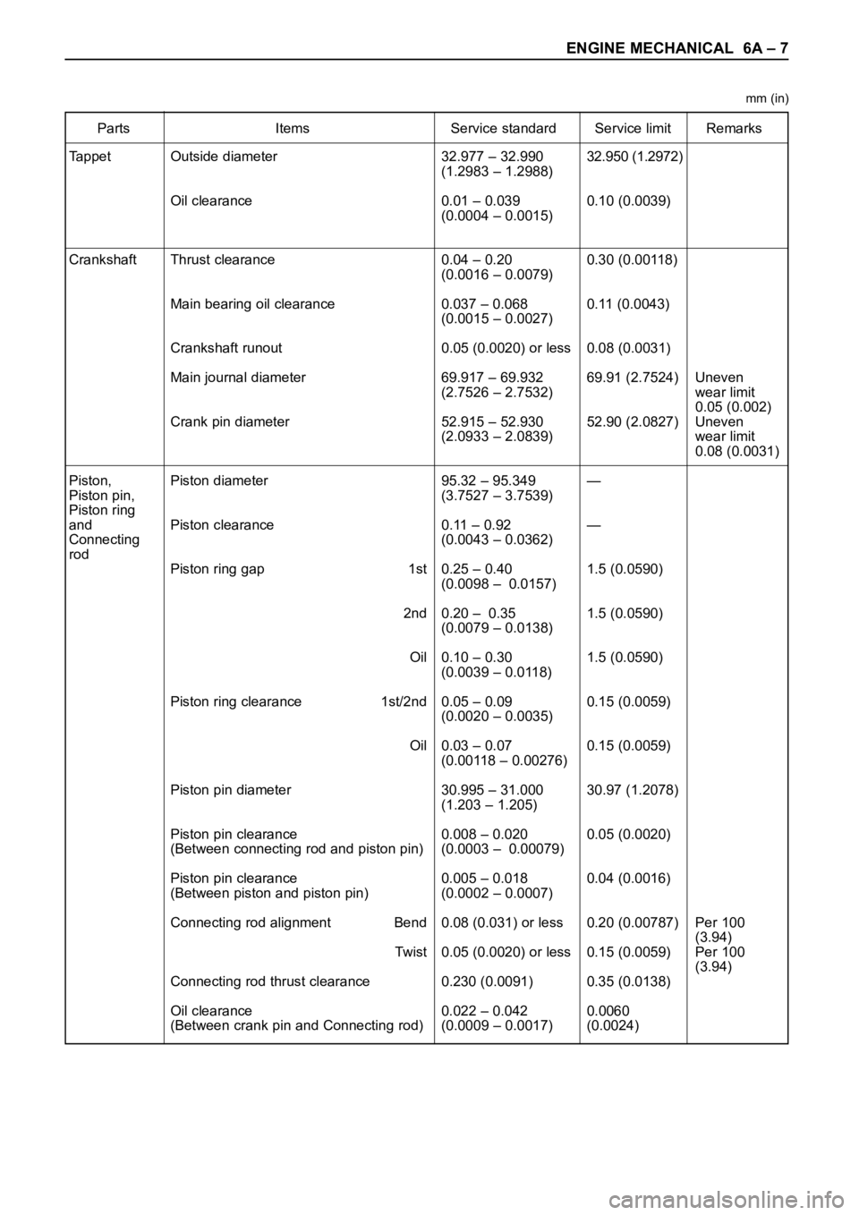
Parts Items Service standard Service limit Remarks
Tappet
Crankshaft
Piston,
Piston pin,
Piston ring
and
Connecting
rod32.977 – 32.990
(1.2983 – 1.2988)
0.01 – 0.039
(0.0004 – 0.0015)
0.04 – 0.20
(0.0016 – 0.0079)
0.037 – 0.068
(0.0015 – 0.0027)
0.05 (0.0020) or less
69.917 – 69.932
(2.7526 – 2.7532)
52.915 – 52.930
(2.0933 – 2.0839)
95.32 – 95.349
(3.7527 – 3.7539)
0.11 – 0.92
(0.0043 – 0.0362)
0.25 – 0.40
(0.0098 – 0.0157)
0.20 – 0.35
(0.0079 – 0.0138)
0.10 – 0.30
(0.0039 – 0.0118)
0.05 – 0.09
(0.0020 – 0.0035)
0.03 – 0.07
(0.00118 – 0.00276)
30.995 – 31.000
(1.203 – 1.205)
0.008 – 0.020
(0.0003 – 0.00079)
0.005 – 0.018
(0.0002 – 0.0007)
0.08 (0.031) or less
0.05 (0.0020) or less
0.230 (0.0091)
0.022 – 0.042
(0.0009 – 0.0017)32.950 (1.2972)
0.10 (0.0039)
0.30 (0.00118)
0.11 (0.0043)
0.08 (0.0031)
69.91 (2.7524)
52.90 (2.0827)
—
—
1.5 (0.0590)
1.5 (0.0590)
1.5 (0.0590)
0.15 (0.0059)
0.15 (0.0059)
30.97 (1.2078)
0.05 (0.0020)
0.04 (0.0016)
0.20 (0.00787)
0.15 (0.0059)
0.35 (0.0138)
0.0060
(0.0024)Uneven
wear limit
0.05 (0.002)
Uneven
wear limit
0.08 (0.0031)
Per 100
(3.94)
Per 100
(3.94) Outside diameter
Oil clearance
Thrust clearance
Main bearing oil clearance
Crankshaft runout
Main journal diameter
Crank pin diameter
Piston diameter
Piston clearance
Piston ring gap 1st
2nd
Oil
Piston ring clearance 1st/2nd
Oil
Piston pin diameter
Piston pin clearance
(Between connecting rod and piston pin)
Piston pin clearance
(Between piston and piston pin)
Connecting rod alignment Bend
Twist
Connecting rod thrust clearance
Oil clearance
(Between crank pin and Connecting rod)
mm (in)
Page 1741 of 6000
6A – 8 ENGINE MECHANICAL
Parts Items Service standard Service limit Remarks
Cylinder
Block—
95.421 – 95.450
(3.7567 – 3.7579)0.20 (0.0079) Warpage
(Upper surface of the cylinder block)
Cylinder bore diameter
Parts Items Service standard Service limit Remarks
Thermostat
Radiator cap83 – 87°C
(181 – 189°F)
More than 9.5 (0.374)
at 100°C (212°F)
88.2 – 117.6 kPa
(12.8 –17.0 psi) Valve opening temperature
Valve full open temperature and lift
Valve opening pressure
Engine Coolingmm (in) mm (in)
Page 1742 of 6000

ENGINE MECHANICAL 6A – 9
SERVICING
Servicing refers to general maintenance procedures to
be performed by qualified service personnel.
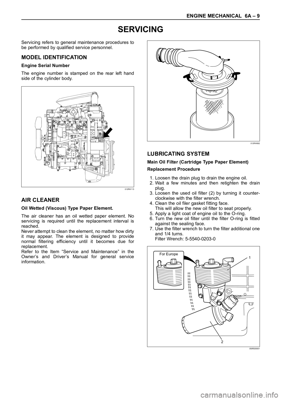
MODEL IDENTIFICATION
Engine Serial Number
The engine number is stamped on the rear left hand
side of the cylinder body.
AIR CLEANER
Oil Wetted (Viscous) Type Paper Element.
The air cleaner has an oil wetted paper element. No
servicing is required until the replacement interval is
reached.
Never attempt to clean the element, no matter how dirty
it may appear. The element is designed to provide
normal filtering efficiency until it becomes due for
replacement.
Refer to the Item “Service and Maintenance” in the
Owner’s and Driver’s Manual for general service
information.
LUBRICATING SYSTEM
Main Oil Filter (Cartridge Type Paper Element)
Replacement Procedure
1. Loosen the drain plug to drain the engine oil.
2. Wait a few minutes and then retighten the drain
plug.
3. Loosen the used oil filter (2) by turning it counter-
clockwise with the filter wrench.
4. Clean the oil filer gasket fitting face.
This will allow the new oil filter to seat properly.
5. Apply a light coat of engine oil to the O-ring.
6. Turn the new oil filter until the filter O-ring is fitted
against the sealing face.
7. Use the filter wrench to turn the filter additional one
and 1/4 turns.
Filter Wrench: 5-5540-0203-0
012RW115
012RW062
For Europe1
2
050R200001
Page 1827 of 6000

6A – 94 ENGINE MECHANICAL
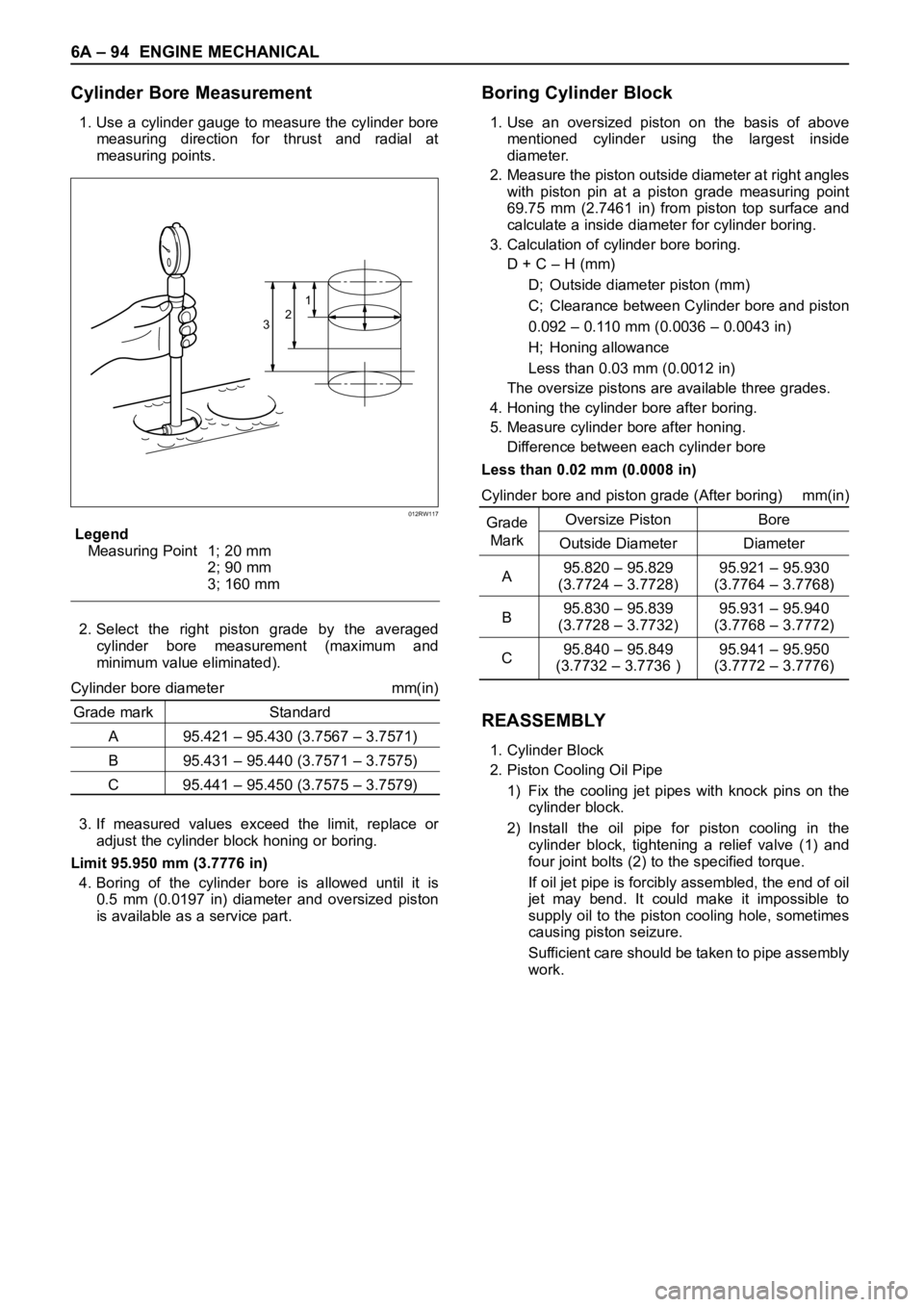
Cylinder Bore Measurement
1. Use a cylinder gauge to measure the cylinder bore
measuring direction for thrust and radial at
measuring points.
Legend
Measuring Point 1; 20 mm
2; 90 mm
3; 160 mm
2. Select the right piston grade by the averaged
cylinder bore measurement (maximum and
minimum value eliminated).
Cylinder bore diameter mm(in)
Grade mark Standard
A 95.421 – 95.430 (3.7567 – 3.7571)
B 95.431 – 95.440 (3.7571 – 3.7575)
C 95.441 – 95.450 (3.7575 – 3.7579)
3. If measured values exceed the limit, replace or
adjust the cylinder block honing or boring.
Limit 95.950 mm (3.7776 in)
4. Boring of the cylinder bore is allowed until it is
0.5 mm (0.0197 in) diameter and oversized piston
is available as a service part.
Boring Cylinder Block
1. Use an oversized piston on the basis of above
mentioned cylinder using the largest inside
diameter.
2. Measure the piston outside diameter at right angles
with piston pin at a piston grade measuring point
69.75 mm (2.7461 in) from piston top surface and
calculate a inside diameter for cylinder boring.
3. Calculation of cylinder bore boring.
D + C – H (mm)
D; Outside diameter piston (mm)
C; Clearance between Cylinder bore and piston
0.092 – 0.110 mm (0.0036 – 0.0043 in)
H; Honing allowance
Less than 0.03 mm (0.0012 in)
The oversize pistons are available three grades.
4. Honing the cylinder bore after boring.
5. Measure cylinder bore after honing.
Difference between each cylinder bore
Less than 0.02 mm (0.0008 in)
Cylinder bore and piston grade (After boring) mm(in)
GradeOversize Piston Bore
Mark
Outside Diameter Diameter
A95.820 – 95.829 95.921 – 95.930
(3.7724 – 3.7728) (3.7764 – 3.7768)
B95.830 – 95.839 95.931 – 95.940
(3.7728 – 3.7732) (3.7768 – 3.7772)
C95.840 – 95.849 95.941 – 95.950
(3.7732 – 3.7736 ) (3.7772 – 3.7776)
REASSEMBLY
1. Cylinder Block
2. Piston Cooling Oil Pipe
1) Fix the cooling jet pipes with knock pins on the
cylinder block.
2) Install the oil pipe for piston cooling in the
cylinder block, tightening a relief valve (1) and
four joint bolts (2) to the specified torque.
If oil jet pipe is forcibly assembled, the end of oil
jet may bend. It could make it impossible to
supply oil to the piston cooling hole, sometimes
causing piston seizure.
Sufficient care should be taken to pipe assembly
work.
321
012RW117
Page 1834 of 6000
ENGINE COOLING 6B – 1
ENGINE COOLING
CONTENTS
General Description . . . . . . . . . . . . . . . . . . 6B–2
On-Vehicle Service . . . . . . . . . . . . . . . . . . . 6B–6
Water Pump . . . . . . . . . . . . . . . . . . . . . . 6B–6Thermostat . . . . . . . . . . . . . . . . . . . . . . . 6B–7
Radiator . . . . . . . . . . . . . . . . . . . . . . . . . 6B–9
Drive Belt Adjustment . . . . . . . . . . . . . . . 6B–11
Page 1839 of 6000

6B – 6 ENGINE COOLING
REMOVAL
1. Drain coolant.
2. AC Generator Drive Belt
1) Loosen AC Generator mounting bolt, adjust
plate lock bolt, and remove the drive belt.
3. Cooling Fan Assembly
1) Remove lock nut and take out cooling fan
assembly with cooling fan clutch.
4. Water Pump Assembly
INSPECTION
Make necessary repair and parts replacement if
excessive wear or damage is found during inspection.
Should any of the following problems occur, the entire
water pump assembly must be replaced.
1) Cracks in the water pump body
2) Coolant leakage from the seal unit
3) Excessive play in radial direction or abnormal noise
4) Excessive play in thrust direction
5) Cracks or corrosion in the impeller
INSTALLATION
1. Gasket
1) Set gasket to gear case.
2. Water Pump Assembly
1) Install water pump assembly, and tighten to
specified torque.Torque: 20 Nꞏm (2.0 kgꞏm/14.5 lb ft)
3. Cooling Fan Assembly
1) Install cooling fan assembly, and tighten to
specified torque.
Torque: 8 Nꞏm (0.8 kgꞏm/5.8 lb ft)
4. AC Generator Drive Belt
1) Install AC Generator drive belt and adjust belt
tension.
Torque: 40 Nꞏm (4.1 kgꞏm/29.7 lb ft)
For ACG to bracket
20 Nꞏm (2.0 kgꞏm/14.5 lb ft)
For ACG to adjust plate
5. Fill coolant to specified capacity.
12
Legend
(1) Fan Pulley
(2) Water Pump Assembly
030RW009
ON-VEHICLE SERVICE
WAT E R P U M P
Page 1846 of 6000

ENGINE FUEL 6C – 1
ENGINE FUEL
CONTENTS
GENERAL DESCRIPTION
General Description . . . . . . . . . . . . . . . . . . 6C–1
On-Vehicle Service . . . . . . . . . . . . . . . . . . 6C–7
Fuel Filter Assembly . . . . . . . . . . . . . . . . 6C–7
Fuel Filter Cartridge . . . . . . . . . . . . . . . . 6C–7
Injector . . . . . . . . . . . . . . . . . . . . . . . . . . 6C–9
Fuel Pump Pipe . . . . . . . . . . . . . . . . . . . 6C–13High Pressure Oil Pump . . . . . . . . . . . . . 6C–15
Fuel Tank . . . . . . . . . . . . . . . . . . . . . . . . 6C–20
Fuel Gauge Unit . . . . . . . . . . . . . . . . . . . 6C–21
Fuel Filler Cap . . . . . . . . . . . . . . . . . . . . 6C–21
To realize the compatibility between low exhaust
emission and high engine output, an HEUI
(Hydraulically actuated Electronically controlled Unit
Injector) system, has been introduced. This system is
comprised of a hydraulic system, fuel system, and
electronic control system, using a high-pressure oil
pump in place of the conventional fuel injection pump.
The oil pressurized by means of this pump and by
signals from the ECM (Electronic Control Module)
actuates the fuel injector provided for each cylinder.
Inside of the fuel injector, fuel pressure is increased due
to the high-pressure oil. The ECM detects the driving
state of the vehicle, forms, signals sent by engine and
other part sensors, which determines the optimum fuel
injection amount and timing, thus controlling the fuel
injectors. Thus high engine output, good fuel economy,
and low exhaust emission are realized.When working on the fuel system, there are several
things to keep in mind:
1) Any time the fuel system is being worked on,
disconnect the negative battery cable except for
those tests where battery voltage is required.
2) Always keep a dry chemical (Class B) fire
extinguisher near the work area.
3) Replace all pipes with the same pipe and fittings
that were removed.
Clean and inspect “O” rings. Replace where
required.
4) Always relieve the line pressure before servicing
any fuel system components.
5) Do not attempt repairs on the fuel system until you
have read the instructions and checked the pictures
relating to that repair.
6) After maintenance work, push priming pump and
send enough fuel to the fuel system before starting
the engine.
NOTE: In comparison with the conventional engine,
the capacity of fuel passage in the 4JX1 engine is
larger. It takes the priming pump more time to fill the
engine with fuel.
Page 1852 of 6000
ENGINE FUEL 6C – 7
ON-VEHICLE SERVICE
FUEL FILTER ASSEMBLY
REMOVAL
1. Disconnect battery ground cable.
2. Fuel Filler cap
3. Fuel Hose
1) Disconnect fuel hose from filter body.
Plug the hose ends to prevent fuel spillage.
4. Remove the Bolt on Fuel Filter Bracket
5. Remove Fuel Filter Assembly
INSTALLATION
1. Install the fuel filter assembly
2. Tighten the Fuel Filter Bracket Fixing Bolt
3. Fuel Hose
1) Connect hoses to filter body.
4. Fuel Filler Cap
1) Connect the battery ground cable.
2) Feed fuel to the fuel pump by priming, and bleed
the air from fuel system.
FUEL FILTER CARTRIDGE
DISASSEMBLY
1. Drain fuel completely from the fuel filter.
2. Protect the filter body with cloth and lightly grip with
a vise.
3. Remove the cartridge using a filter wrench.
Filter wrench: 5-8840-0203-0
1
Legend
(1) Priming Pump
012RW111
012RW112