Page 1 of 29

FRONT AXLE &
FRONT SUSPENSION
SECTION
FA
CONTENTS
PRECAUTIONS AND PREPARATION............................1
Precautions ..................................................................1
Special Service Tools ..................................................1
Commercial Service Tools ...........................................2
NOISE, VIBRATION AND HARSHNESS (NVH)
TROUBLESHOOTING.....................................................3
NVH Troubleshooting Chart.........................................3
FRONT AXLE AND FRONT SUSPENSION...................4
ON-VEHICLE SERVICE..................................................5
Front Axle and Front Suspension Parts ......................5
Front Wheel Bearing....................................................5
Front Wheel Alignment ................................................8
FRONT AXLE Ð Drive ¯ange and Free-running
Hub.................................................................................10
FRONT AXLE Ð Manual-lock Free-running Hub...... 11
Removal ..................................................................... 11
Installation ..................................................................12
Inspection...................................................................12
FRONT AXLE Ð Auto-lock Free-running Hub..........13
Removal .....................................................................13
Installation ..................................................................13FRONT AXLE Ð Wheel Hub and Rotor Disc............14
Removal and Installation ...........................................14
Inspection...................................................................15
Assembly ...................................................................15
FRONT AXLE Ð Knuckle Flange................................17
Removal .....................................................................17
Inspection...................................................................19
Installation ..................................................................19
Knuckle Flange Grease Seal.....................................21
FRONT AXLE Ð Drive Shaft.......................................23
Inspection...................................................................23
Installation ..................................................................23
FRONT SUSPENSION..................................................24
Shock Absorber .........................................................25
Stabilizer Bar .............................................................25
Coil Spring .................................................................25
Leading Arm...............................................................26
Panhard Rod..............................................................26
SERVICE DATA AND SPECIFICATIONS (SDS)..........27
General Speci®cations ...............................................27
Inspection and Adjustment ........................................27
FA
Page 2 of 29
Precautions
+When installing rubber parts, ®nal tightening must be car-
ried out under unladen condition* with tires on ground.
* Fuel, radiator coolant and engine oil full. Spare tire, jack,
hand tools and mats in designated positions.
+Use ¯are nut wrench when removing and installing brake
tubes.
+After installing removed suspension parts, check wheel
alignment and adjust if necessary.
+Always torque brake lines when installing.
Special Service Tools
Tool number
Tool nameDescription
ST29020001
Gear arm puller
NT551
Removing tie-rod and drag link
a: 34 mm (1.34 in)
b: 6.5 mm (0.256 in)
c: 61.5 mm (2.421 in)
KV401021S0
Bearing race drift
NT153
Installing wheel bearing outer race
KV40105400
Wheel bearing
lock nut wrench
NT154
Removing and installing wheel bearing lock
nut
GG94310000
Flare nut torque wrench
NT406
Removing and installing brake piping
a: 10 mm (0.39 in)
SBR820BA
PRECAUTIONS AND PREPARATION
FA-1
Page 4 of 29

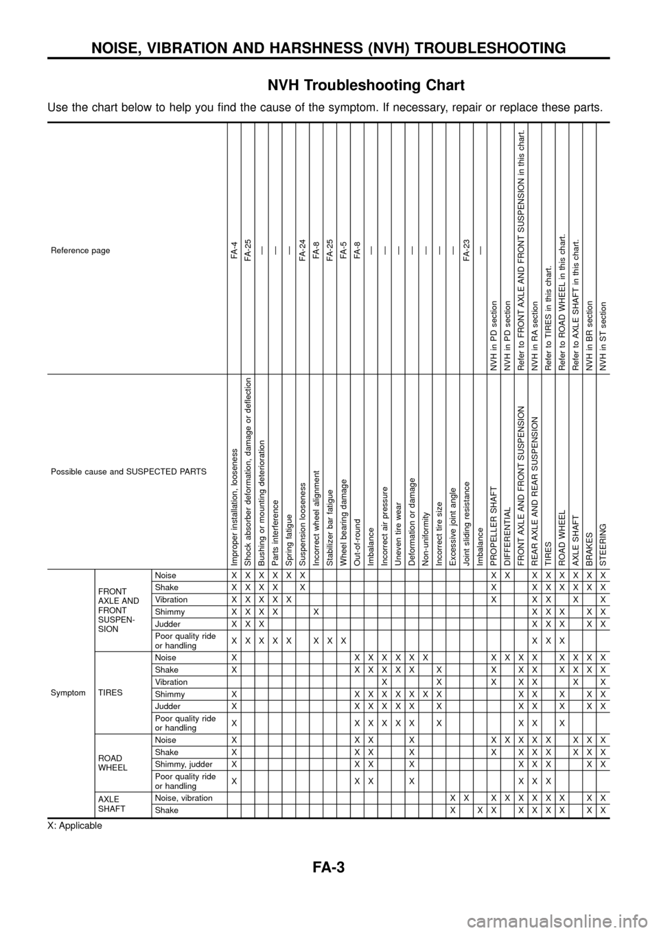
NVH Troubleshooting Chart
Use the chart below to help you ®nd the cause of the symptom. If necessary, repair or replace these parts.
Reference pageFA-4
FA-25
Ð
Ð
Ð
FA-24
FA-8
FA-25
FA-5
FA-8
Ð
Ð
Ð
Ð
Ð
Ð
Ð
FA-23
Ð
NVH in PD section
NVH in PD section
Refer to FRONT AXLE AND FRONT SUSPENSION in this chart.
NVH in RA section
Refer to TIRES in this chart.
Refer to ROAD WHEEL in this chart.
Refer to AXLE SHAFT in this chart.
NVH in BR section
NVH in ST section
Possible cause and SUSPECTED PARTS
Improper installation, looseness
Shock absorber deformation, damage or de¯ection
Bushing or mounting deterioration
Parts interference
Spring fatigue
Suspension looseness
Incorrect wheel alignment
Stabilizer bar fatigue
Wheel bearing damage
Out-of-round
Imbalance
Incorrect air pressure
Uneven tire wear
Deformation or damage
Non-uniformity
Incorrect tire size
Excessive joint angle
Joint sliding resistance
Imbalance
PROPELLER SHAFT
DIFFERENTIAL
FRONT AXLE AND FRONT SUSPENSION
REAR AXLE AND REAR SUSPENSION
TIRES
ROAD WHEEL
AXLE SHAFT
BRAKES
STEERING
SymptomFRONT
AXLE AND
FRONT
SUSPEN-
SIONNoiseXXXXXX XX XXXXXX
ShakeXXXX X X XXXXXX
VibrationXXXXX X XX X X
ShimmyXXXX X XXX XX
Judder X X XXXX XX
Poor quality ride
or handlingXXXXX XXX XXX
TIRESNoise XXXXXXX XXXX XXXX
Shake XXXXXX X X XX XXXX
Vibration X X X X X X X
Shimmy XXXXXXXX XX X XX
Judder XXXXXX X XX X XX
Poor quality ride
or handlingX XXXXX X XX X
ROAD
WHEELNoise X X X XXXXXX XXX
Shake X X X X X X X X X X X
Shimmy, judder X X X X X X X X X
Poor quality ride
or handlingX XX X XXX
AXLE
SHAFTNoise, vibration X XXXXXXX XX
ShakeX XX XXXX XX
X: Applicable
NOISE, VIBRATION AND HARSHNESS (NVH) TROUBLESHOOTING
FA-3
Page 5 of 29
SFA850B
FRONT AXLE AND FRONT SUSPENSION
FA-4
Page 6 of 29
Front Axle and Front Suspension Parts
Check front axle and front suspension parts for excessive play,
cracks, wear and other damage.
+Shake each front wheel to check for excessive play.
+Make sure that cotter pin is inserted.
+Retighten all axle and suspensions nuts and bolts to the speci-
®ed torque.
Tightening torque:
Refer to FRONT SUSPENSION (FA-24).
+Check front axle and front suspension parts for wear, cracks
and other damage.
+Check shock absorber for oil leakage and other damage.
+Check knuckle ¯ange for grease leakage and knuckle ¯ange
grease seal for cracks and other damage.
Front Wheel Bearing
+Check that wheel bearings operate smoothly.
+Check axial end play.
Axial end play:
0mm(0in)
+Adjust wheel bearing preload if there is any axial end play or
wheel bearing does not turn smoothly.
SMA525A
SFA851B
SFA852B
SFA413A
ON-VEHICLE SERVICE
FA-5
Page 9 of 29

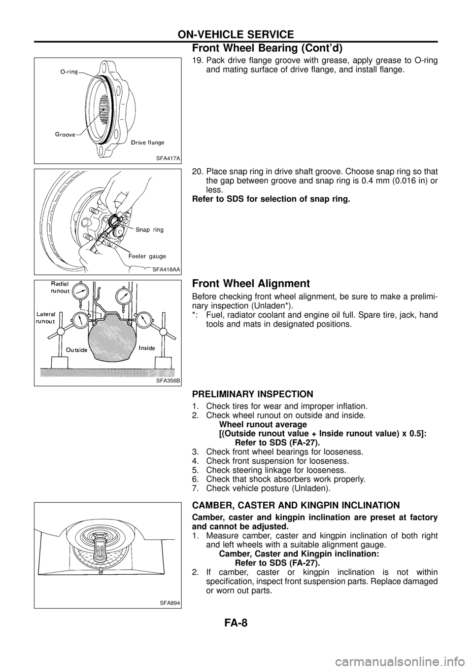
19. Pack drive ¯ange groove with grease, apply grease to O-ring
and mating surface of drive ¯ange, and install ¯ange.
20. Place snap ring in drive shaft groove. Choose snap ring so that
the gap between groove and snap ring is 0.4 mm (0.016 in) or
less.
Refer to SDS for selection of snap ring.
Front Wheel Alignment
Before checking front wheel alignment, be sure to make a prelimi-
nary inspection (Unladen*).
*: Fuel, radiator coolant and engine oil full. Spare tire, jack, hand
tools and mats in designated positions.
PRELIMINARY INSPECTION
1. Check tires for wear and improper in¯ation.
2. Check wheel runout on outside and inside.
Wheel runout average
[(Outside runout value + Inside runout value) x 0.5]:
Refer to SDS (FA-27).
3. Check front wheel bearings for looseness.
4. Check front suspension for looseness.
5. Check steering linkage for looseness.
6. Check that shock absorbers work properly.
7. Check vehicle posture (Unladen).
CAMBER, CASTER AND KINGPIN INCLINATION
Camber, caster and kingpin inclination are preset at factory
and cannot be adjusted.
1. Measure camber, caster and kingpin inclination of both right
and left wheels with a suitable alignment gauge.
Camber, Caster and Kingpin inclination:
Refer to SDS (FA-27).
2. If camber, caster or kingpin inclination is not within
speci®cation, inspect front suspension parts. Replace damaged
or worn out parts.
SFA417A
SFA418AA
SFA356B
SFA894
ON-VEHICLE SERVICE
Front Wheel Bearing (Cont'd)
FA-8
Page 25 of 29
SFA889B
FRONT SUSPENSION
FA-24
Page 26 of 29

Shock Absorber
REMOVAL AND INSTALLATION
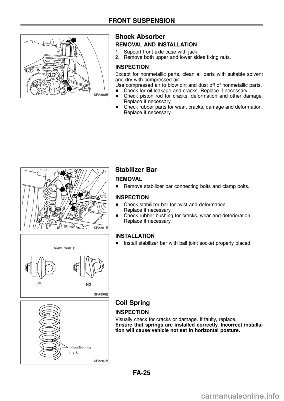
1. Support front axle case with jack.
2. Remove both upper and lower sides ®xing nuts.
INSPECTION
Except for nonmetallic parts, clean all parts with suitable solvent
and dry with compressed air.
Use compressed air to blow dirt and dust off of nonmetallic parts.
+Check for oil leakage and cracks. Replace if necessary.
+Check piston rod for cracks, deformation and other damage.
Replace if necessary.
+Check rubber parts for wear, cracks, damage and deformation.
Replace if necessary.
Stabilizer Bar
REMOVAL
+Remove stabilizer bar connecting bolts and clamp bolts.
INSPECTION
+Check stabilizer bar for twist and deformation.
Replace if necessary.
+Check rubber bushing for cracks, wear and deterioration.
Replace if necessary.
INSTALLATION
+Install stabilizer bar with ball joint socket properly placed.
Coil Spring
INSPECTION
Visually check for cracks or damage. If faulty, replace.
Ensure that springs are installed correctly. Incorrect installa-
tion will cause vehicle not set in horizontal posture.
SFA890B
SFA891B
SFA896B
SFA897B
FRONT SUSPENSION
FA-25