Page 3 of 22
Special Service Tools*: Special tool or commercial equivalent
Tool number
Tool nameDescription
ST25051001*
Oil pressure gauge
NT558
Measuring oil pressure
Maximum measuring range:
2,452 kPa (24.5 bar, 25
kg/cm
2, 356 psi)
ST25052000*
Hose
NT559
Adapting oil pressure gauge
to cylinder block
EG17650301
Radiator cap tester
adapter
NT564
Adapting radiator cap tester
to radiator ®ller neck
a: 28 (1.10) dia.
b: 31.4 (1.236) dia.
c: 41.3 (1.626) dia.
Unit: mm (in)
KV99103510
Radiator plate pliers A
NT224
Installing radiator upper and
lower tanks
KV99103520
Radiator plate pliers B
NT225
Removing radiator upper and
lower tanks
WS39930000
Tube presser
NT052
Pressing the tube of liquid gas-
ket
PRECAUTIONS AND PREPARATION
LC-2
Page 5 of 22

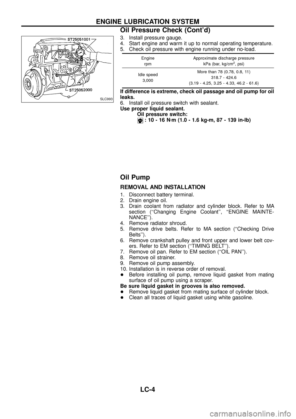
3. Install pressure gauge.
4. Start engine and warm it up to normal operating temperature.
5. Check oil pressure with engine running under no-load.
Engine
rpmApproximate discharge pressure
kPa (bar, kg/cm2, psi)
Idle speed
3,000More than 78 (0.78, 0.8, 11)
318.7 - 424.6
(3.19 - 4.25, 3.25 - 4.33, 46.2 - 61.6)
If difference is extreme, check oil passage and oil pump for oil
leaks.
6. Install oil pressure switch with sealant.
Use proper liquid sealant.
Oil pressure switch:
:10-16Nzm (1.0 - 1.6 kg-m, 87 - 139 in-lb)
Oil Pump
REMOVAL AND INSTALLATION
1. Disconnect battery terminal.
2. Drain engine oil.
3. Drain coolant from radiator and cylinder block. Refer to MA
section (``Changing Engine Coolant'', ``ENGINE MAINTE-
NANCE'').
4. Remove radiator shroud.
5. Remove drive belts. Refer to MA section (``Checking Drive
Belts'').
6. Remove crankshaft pulley and front upper and lower belt cov-
ers. Refer to EM section (``TIMING BELT'').
7. Remove oil pan. Refer to EM section (``OIL PAN'').
8. Remove oil strainer.
9. Remove oil pump assembly.
10. Installation is in reverse order of removal.
+Before installing oil pump, remove liquid gasket from mating
surface of oil pump using a scraper.
Be sure liquid gasket in grooves is also removed.
+Remove liquid gasket from mating surface of cylinder block.
+Clean all traces of liquid gasket using white gasoline.
SLC993
ENGINE LUBRICATION SYSTEM
Oil Pressure Check (Cont'd)
LC-4
Page 9 of 22
When installing oil jet, align oil jet's boss with hole on cylin-
der block.
Oil jet bolt:
:30-40Nzm (3.1 - 4.1 kg-m, 22 - 30 ft-lb)
Turbocharger
+Before removing water tube, drain coolant ®rst.
+Be careful not to deform tubes.
+After installation, run engine for a few minutes, and check
for oil leakage.
SLC975
SLC197B
ENGINE LUBRICATION SYSTEM
Oil Jet (Cont'd)
LC-8
Page 11 of 22

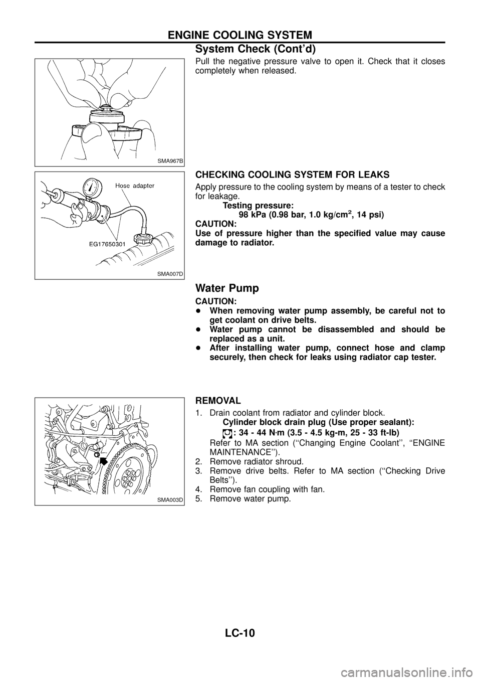
Pull the negative pressure valve to open it. Check that it closes
completely when released.
CHECKING COOLING SYSTEM FOR LEAKS
Apply pressure to the cooling system by means of a tester to check
for leakage.
Testing pressure:
98 kPa (0.98 bar, 1.0 kg/cm
2, 14 psi)
CAUTION:
Use of pressure higher than the speci®ed value may cause
damage to radiator.
Water Pump
CAUTION:
+When removing water pump assembly, be careful not to
get coolant on drive belts.
+Water pump cannot be disassembled and should be
replaced as a unit.
+After installing water pump, connect hose and clamp
securely, then check for leaks using radiator cap tester.
REMOVAL
1. Drain coolant from radiator and cylinder block.
Cylinder block drain plug (Use proper sealant):
:34-44Nzm (3.5 - 4.5 kg-m, 25 - 33 ft-lb)
Refer to MA section (``Changing Engine Coolant'', ``ENGINE
MAINTENANCE'').
2. Remove radiator shroud.
3. Remove drive belts. Refer to MA section (``Checking Drive
Belts'').
4. Remove fan coupling with fan.
5. Remove water pump.
SMA967B
SMA007D
SMA003D
ENGINE COOLING SYSTEM
System Check (Cont'd)
LC-10
Page 12 of 22
INSPECTION
1. Check for rusted or corroded body assembly and vane.
2. Check for excessive end play and rough operation.
INSTALLATION
+Remove liquid gasket from mating surface of pump housing
using a scraper.
Be sure liquid gasket in grooves is also removed.
+Remove liquid gasket from mating surface of cylinder block.
+Clean all traces of liquid gasket using white gasoline.
+Cut off tip of nozzle of liquid gasket tube at point shown in ®g-
ure.
+Use Genuine Liquid Gasket or equivalent.
SLC997-A
SLC998
SLC822
ENGINE COOLING SYSTEM
Water Pump (Cont'd)
LC-11
Page 13 of 22
+Apply a continuous bead of liquid gasket to mating surface of
pump housing as shown.
a. Be sure diameter of liquid gasket is within 2.0 to 3.0 mm
(0.079 to 0.118 in) dia. range.
b. Attach pump housing to cylinder block within ®ve minutes
of applying liquid gasket.
c. After installing pump housing, wait at least 30 minutes
before starting engine.
Thermostat
INSPECTION
1. Check valve seating condition at ordinary temperatures. It
should seat tightly.
2. Check valve opening temperature and maximum valve lift.
Valve opening temperature CÉ (ÉF) 82.0 (180)
Maximum valve lift mm/ÉC (in/ÉF) 10/90 (0.39/194)
3. Then check if valve closes at 5ÉC (9ÉF) below valve opening
temperature.
INSTALLATION
+Remove liquid gasket from mating surface of thermostat using
a scraper.
+Similarly, remove liquid gasket from mating surface of cylinder
block.
+Clean all traces of liquid gasket using white gasoline.
SLC001A
SLC002A
SLC343
SLC790
Scraper
ENGINE COOLING SYSTEM
Water Pump (Cont'd)
LC-12
Page 14 of 22
+Cut off tip of nozzle of liquid gasket at point shown in ®gure.
+Use Genuine Liquid Gasket or equivalent.
+Apply a continuous bead of liquid gasket to mating surface of
water inlet.
a. Be sure diameter of liquid gasket is within 2.0 to 3.0 mm (0.079
to 0.118 in).
b. Attach water inlet to cylinder block within ®ve minutes after
applying liquid gasket.
c. After installing water inlet, wait at least 30 minutes before re®ll-
ing coolant and starting engine.
SLC822
SLC824 Diameter of liquid gasket:
2.0 - 3.0 mm (0.079 - 0.118 in)
ENGINE COOLING SYSTEM
Thermostat (Cont'd)
LC-13
Page 21 of 22

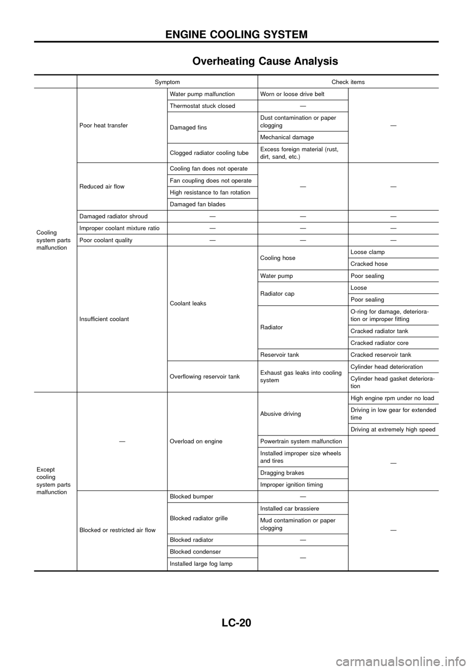
Overheating Cause Analysis
Symptom Check items
Cooling
system parts
malfunctionPoor heat transferWater pump malfunction Worn or loose drive belt
Ð Thermostat stuck closed Ð
Damaged ®nsDust contamination or paper
clogging
Mechanical damage
Clogged radiator cooling tubeExcess foreign material (rust,
dirt, sand, etc.)
Reduced air ¯owCooling fan does not operate
ÐÐ Fan coupling does not operate
High resistance to fan rotation
Damaged fan blades
Damaged radiator shroud Ð Ð Ð
Improper coolant mixture ratio Ð Ð Ð
Poor coolant quality Ð Ð Ð
Insufficient coolantCoolant leaksCooling hoseLoose clamp
Cracked hose
Water pump Poor sealing
Radiator capLoose
Poor sealing
RadiatorO-ring for damage, deteriora-
tion or improper ®tting
Cracked radiator tank
Cracked radiator core
Reservoir tank Cracked reservoir tank
Over¯owing reservoir tankExhaust gas leaks into cooling
systemCylinder head deterioration
Cylinder head gasket deteriora-
tion
Except
cooling
system parts
malfunctionÐ Overload on engineAbusive drivingHigh engine rpm under no load
Driving in low gear for extended
time
Driving at extremely high speed
Powertrain system malfunction
Ð Installed improper size wheels
and tires
Dragging brakes
Improper ignition timing
Blocked or restricted air ¯owBlocked bumper Ð
Ð Blocked radiator grilleInstalled car brassiere
Mud contamination or paper
clogging
Blocked radiator Ð
Blocked condenser
Ð
Installed large fog lamp
ENGINE COOLING SYSTEM
LC-20