Page 147 of 192

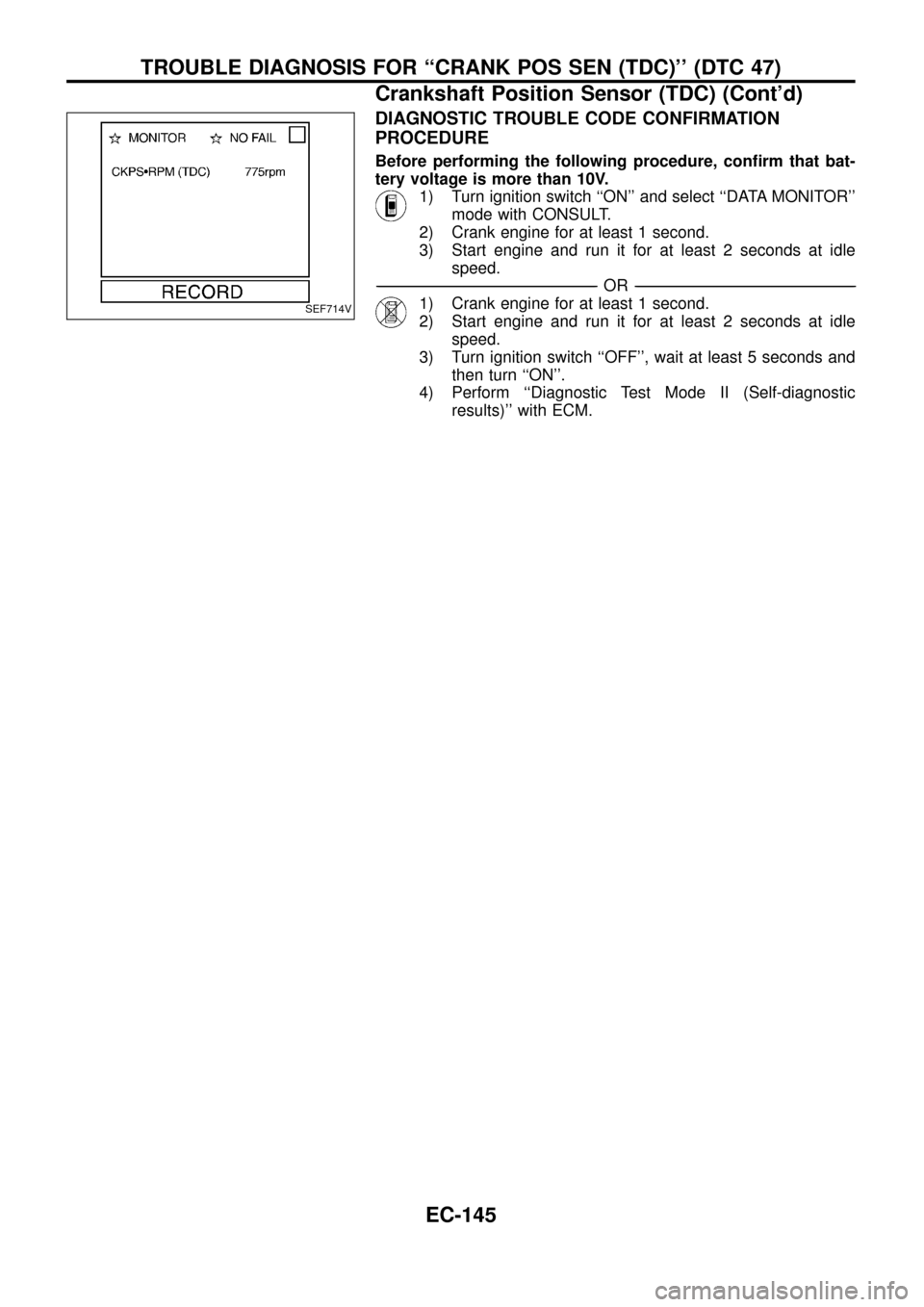
DIAGNOSTIC TROUBLE CODE CONFIRMATION
PROCEDURE
Before performing the following procedure, con®rm that bat-
tery voltage is more than 10V.
1) Turn ignition switch ``ON'' and select ``DATA MONITOR''
mode with CONSULT.
2) Crank engine for at least 1 second.
3) Start engine and run it for at least 2 seconds at idle
speed.
-------------------------------------------------------------------------------------------------------------------------------------------------------------------------------------------------------------------------------------------------------OR-------------------------------------------------------------------------------------------------------------------------------------------------------------------------------------------------------------------------------------------------------
1) Crank engine for at least 1 second.
2) Start engine and run it for at least 2 seconds at idle
speed.
3) Turn ignition switch ``OFF'', wait at least 5 seconds and
then turn ``ON''.
4) Perform ``Diagnostic Test Mode II (Self-diagnostic
results)'' with ECM.SEF714V
TROUBLE DIAGNOSIS FOR ``CRANK POS SEN (TDC)'' (DTC 47)
Crankshaft Position Sensor (TDC) (Cont'd)
EC-145
Page 151 of 192

Governor Cut Circuit
ON BOARD DIAGNOSIS LOGIC
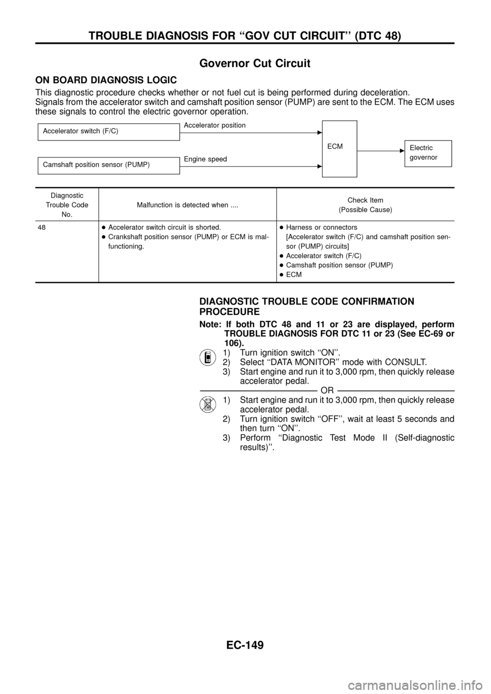
This diagnostic procedure checks whether or not fuel cut is being performed during deceleration.
Signals from the accelerator switch and camshaft position sensor (PUMP) are sent to the ECM. The ECM uses
these signals to control the electric governor operation.
Accelerator switch (F/C)cAccelerator position
ECM
cElectric
governor
Camshaft position sensor (PUMP)cEngine speed
Diagnostic
Trouble Code
No.Malfunction is detected when ....Check Item
(Possible Cause)
48+Accelerator switch circuit is shorted.
+Crankshaft position sensor (PUMP) or ECM is mal-
functioning.+Harness or connectors
[Accelerator switch (F/C) and camshaft position sen-
sor (PUMP) circuits]
+Accelerator switch (F/C)
+Camshaft position sensor (PUMP)
+ECM
DIAGNOSTIC TROUBLE CODE CONFIRMATION
PROCEDURE
Note: If both DTC 48 and 11 or 23 are displayed, perform
TROUBLE DIAGNOSIS FOR DTC 11 or 23 (See EC-69 or
106).
1) Turn ignition switch ``ON''.
2) Select ``DATA MONITOR'' mode with CONSULT.
3) Start engine and run it to 3,000 rpm, then quickly release
accelerator pedal.
-------------------------------------------------------------------------------------------------------------------------------------------------------------------------------------------------------------------------------------------------------OR-------------------------------------------------------------------------------------------------------------------------------------------------------------------------------------------------------------------------------------------------------
1) Start engine and run it to 3,000 rpm, then quickly release
accelerator pedal.
2) Turn ignition switch ``OFF'', wait at least 5 seconds and
then turn ``ON''.
3) Perform ``Diagnostic Test Mode II (Self-diagnostic
results)''.
TROUBLE DIAGNOSIS FOR ``GOV CUT CIRCUIT'' (DTC 48)
EC-149
Page 166 of 192

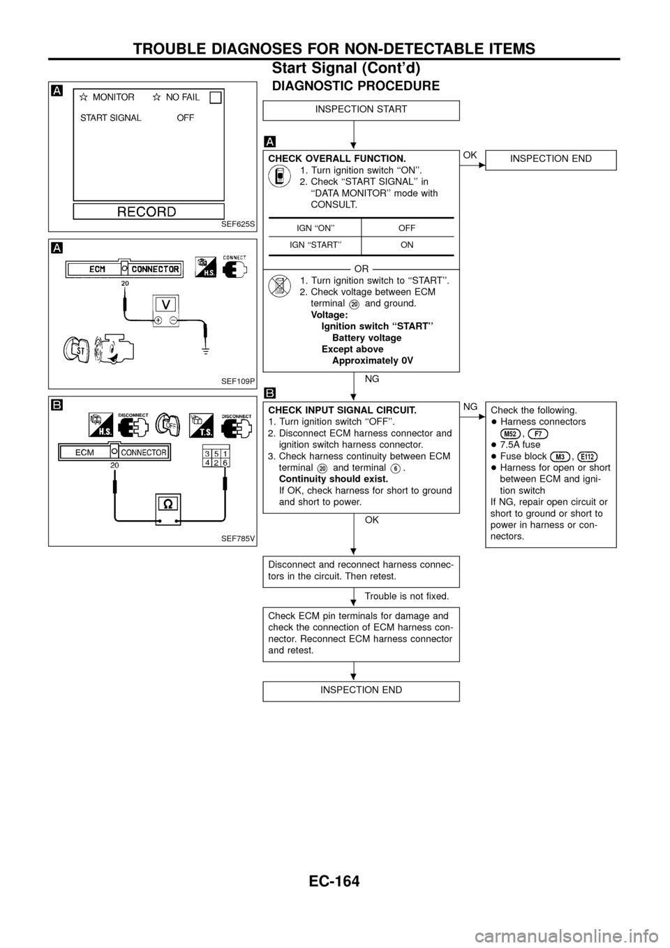
DIAGNOSTIC PROCEDURE
INSPECTION START
CHECK OVERALL FUNCTION.
1. Turn ignition switch ``ON''.
2. Check ``START SIGNAL'' in
``DATA MONITOR'' mode with
CONSULT.
--------------------------------------------------------------------------------------------------------------------------------------OR--------------------------------------------------------------------------------------------------------------------------------------
1. Turn ignition switch to ``START''.
2. Check voltage between ECM
terminal
V20and ground.
Voltage:
Ignition switch ``START''
Battery voltage
Except above
Approximately 0V
NG
cOK
INSPECTION END
CHECK INPUT SIGNAL CIRCUIT.
1. Turn ignition switch ``OFF''.
2. Disconnect ECM harness connector and
ignition switch harness connector.
3. Check harness continuity between ECM
terminal
V20and terminalV6.
Continuity should exist.
If OK, check harness for short to ground
and short to power.
OK
cNG
Check the following.
+Harness connectors
M52,F7
+7.5A fuse
+Fuse block
M3,E112
+Harness for open or short
between ECM and igni-
tion switch
If NG, repair open circuit or
short to ground or short to
power in harness or con-
nectors.
Disconnect and reconnect harness connec-
tors in the circuit. Then retest.
Trouble is not ®xed.
Check ECM pin terminals for damage and
check the connection of ECM harness con-
nector. Reconnect ECM harness connector
and retest.
INSPECTION END
IGN ``ON'' OFF
IGN ``START'' ONSEF625S
SEF109P
SEF785V
.
.
.
.
.
TROUBLE DIAGNOSES FOR NON-DETECTABLE ITEMS
Start Signal (Cont'd)
EC-164