1998 NISSAN PATROL engine coolant
[x] Cancel search: engine coolantPage 84 of 192
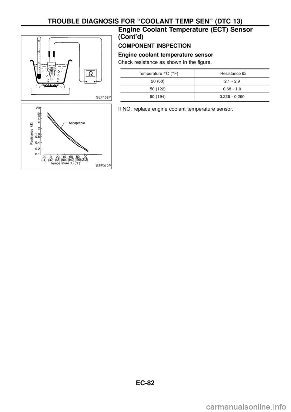
COMPONENT INSPECTION
Engine coolant temperature sensor
Check resistance as shown in the ®gure.
Temperature ÉC (ÉF) Resistance kW
20 (68) 2.1 - 2.9
50 (122) 0.68 - 1.0
90 (194) 0.236 - 0.260
If NG, replace engine coolant temperature sensor.
SEF152P
SEF012P
TROUBLE DIAGNOSIS FOR ``COOLANT TEMP SEN'' (DTC 13)
Engine Coolant Temperature (ECT) Sensor
(Cont'd)
EC-82
Page 115 of 192
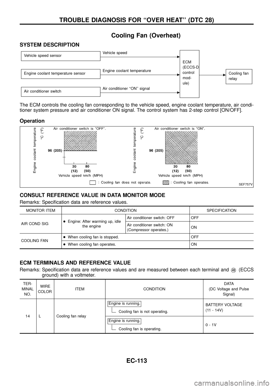
Cooling Fan (Overheat)
SYSTEM DESCRIPTION
Vehicle speed sensorcVehicle speed
ECM
(ECCS-D
control
mod-
ule)
cCooling fan
relayEngine coolant temperature sensorcEngine coolant temperature
Air conditioner switch
cAir conditioner ``ON'' signal
The ECM controls the cooling fan corresponding to the vehicle speed, engine coolant temperature, air condi-
tioner system pressure and air conditioner ON signal. The control system has 2-step control [ON/OFF].
Operation
CONSULT REFERENCE VALUE IN DATA MONITOR MODE
Remarks: Speci®cation data are reference values.
MONITOR ITEM CONDITION SPECIFICATION
AIR COND SIG+Engine: After warming up, idle
the engineAir conditioner switch: OFF OFF
Air conditioner switch: ON
(Compressor operates.)ON
COOLING FAN+When cooling fan is stopped. OFF
+When cooling fan operates. ON
ECM TERMINALS AND REFERENCE VALUE
Remarks: Speci®cation data are reference values and are measured between each terminal andV43(ECCS
ground) with a voltmeter.
TER-
MINAL
NO.WIRE
COLORITEM CONDITIONDATA
(DC Voltage and Pulse
Signal)
14 L Cooling fan relayEngine is running.
Cooling fan is not operating.BATTERY VOLTAGE
(11 - 14V)
Engine is running.
Cooling fan is operating.0-1V
SEF757V
TROUBLE DIAGNOSIS FOR ``OVER HEAT'' (DTC 28)
EC-113
Page 116 of 192
TER-
MINAL
NO.WIRE
COLORITEM CONDITIONDATA
(DC Voltage and Pulse
Signal)
15 Y/L Air conditioner relayEngine is running.
Air conditioner switch is ``OFF''.BATTERY VOLTAGE
(11 - 14V)
Engine is running.
Both air conditioner switch and blower fan
switch are ``ON''.
(Compressor is operating.)0-1V
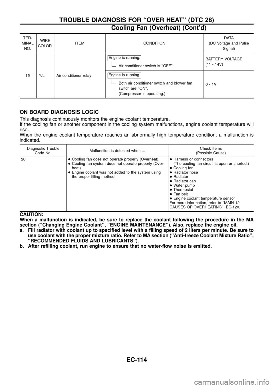
ON BOARD DIAGNOSIS LOGIC
This diagnosis continuously monitors the engine coolant temperature.
If the cooling fan or another component in the cooling system malfunctions, engine coolant temperature will
rise.
When the engine coolant temperature reaches an abnormally high temperature condition, a malfunction is
indicated.
Diagnostic Trouble
Code No.Malfunction is detected when ...Check Items
(Possible Cause)
28+Cooling fan does not operate properly (Overheat).
+Cooling fan system does not operate properly (Over-
heat).
+Engine coolant was not added to the system using
the proper ®lling method.+Harness or connectors
(The cooling fan circuit is open or shorted.)
+Cooling fan
+Radiator hose
+Radiator
+Radiator cap
+Water pump
+Thermostat
+Fan belt
+Engine coolant temperature sensor
For more information, refer to ``MAIN 12
CAUSES OF OVERHEATING'', EC-120.
CAUTION:
When a malfunction is indicated, be sure to replace the coolant following the procedure in the MA
section (``Changing Engine Coolant'', ``ENGINE MAINTENANCE''). Also, replace the engine oil.
a. Fill radiator with coolant up to speci®ed level with a ®lling speed of 2 liters per minute. Be sure to
use coolant with the proper mixture ratio. Refer to MA section (``Anti-freeze Coolant Mixture Ratio'',
``RECOMMENDED FLUIDS AND LUBRICANTS'').
b. After re®lling coolant, run engine to ensure that no water-¯ow noise is emitted.
TROUBLE DIAGNOSIS FOR ``OVER HEAT'' (DTC 28)
Cooling Fan (Overheat) (Cont'd)
EC-114
Page 117 of 192
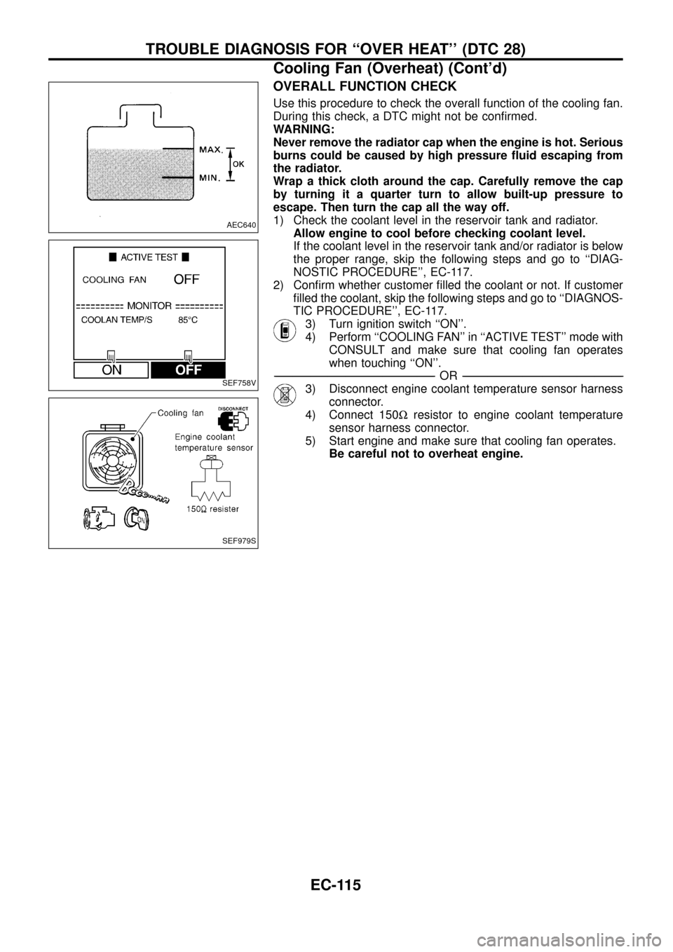
OVERALL FUNCTION CHECK
Use this procedure to check the overall function of the cooling fan.
During this check, a DTC might not be con®rmed.
WARNING:
Never remove the radiator cap when the engine is hot. Serious
burns could be caused by high pressure ¯uid escaping from
the radiator.
Wrap a thick cloth around the cap. Carefully remove the cap
by turning it a quarter turn to allow built-up pressure to
escape. Then turn the cap all the way off.
1) Check the coolant level in the reservoir tank and radiator.
Allow engine to cool before checking coolant level.
If the coolant level in the reservoir tank and/or radiator is below
the proper range, skip the following steps and go to ``DIAG-
NOSTIC PROCEDURE'', EC-117.
2) Con®rm whether customer ®lled the coolant or not. If customer
®lled the coolant, skip the following steps and go to ``DIAGNOS-
TIC PROCEDURE'', EC-117.
3) Turn ignition switch ``ON''.
4) Perform ``COOLING FAN'' in ``ACTIVE TEST'' mode with
CONSULT and make sure that cooling fan operates
when touching ``ON''.
-------------------------------------------------------------------------------------------------------------------------------------------------------------------------------------------------------------------------------------------------------OR-------------------------------------------------------------------------------------------------------------------------------------------------------------------------------------------------------------------------------------------------------
3) Disconnect engine coolant temperature sensor harness
connector.
4) Connect 150Wresistor to engine coolant temperature
sensor harness connector.
5) Start engine and make sure that cooling fan operates.
Be careful not to overheat engine.
AEC640
SEF758V
SEF979S
TROUBLE DIAGNOSIS FOR ``OVER HEAT'' (DTC 28)
Cooling Fan (Overheat) (Cont'd)
EC-115
Page 119 of 192
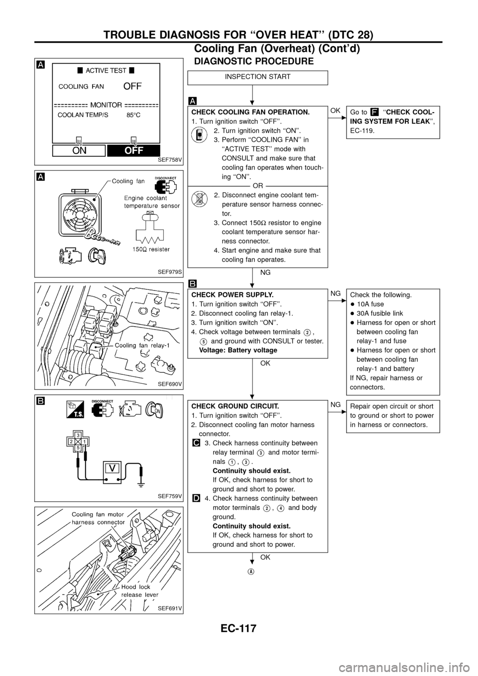
DIAGNOSTIC PROCEDURE
INSPECTION START
CHECK COOLING FAN OPERATION.
1. Turn ignition switch ``OFF''.
2. Turn ignition switch ``ON''.
3. Perform ``COOLING FAN'' in
``ACTIVE TEST'' mode with
CONSULT and make sure that
cooling fan operates when touch-
ing ``ON''.
--------------------------------------------------------------------------------------------------------------------------------------OR--------------------------------------------------------------------------------------------------------------------------------------
2. Disconnect engine coolant tem-
perature sensor harness connec-
tor.
3. Connect 150Wresistor to engine
coolant temperature sensor har-
ness connector.
4. Start engine and make sure that
cooling fan operates.
NG
cOK
Go to``CHECK COOL-
ING SYSTEM FOR LEAK'',
EC-119.
CHECK POWER SUPPLY.
1. Turn ignition switch ``OFF''.
2. Disconnect cooling fan relay-1.
3. Turn ignition switch ``ON''.
4. Check voltage between terminals
V2,
V5and ground with CONSULT or tester.
Voltage: Battery voltage
OK
cNG
Check the following.
+10A fuse
+30A fusible link
+Harness for open or short
between cooling fan
relay-1 and fuse
+Harness for open or short
between cooling fan
relay-1 and battery
If NG, repair harness or
connectors.
CHECK GROUND CIRCUIT.
1. Turn ignition switch ``OFF''.
2. Disconnect cooling fan motor harness
connector.
3. Check harness continuity between
relay terminal
V3and motor termi-
nals
V1,V3.
Continuity should exist.
If OK, check harness for short to
ground and short to power.
4. Check harness continuity between
motor terminals
V2,V4and body
ground.
Continuity should exist.
If OK, check harness for short to
ground and short to power.
OK
cNG
Repair open circuit or short
to ground or short to power
in harness or connectors.
jA
SEF758V
SEF979S
SEF690V
SEF759V
SEF691V
.
.
.
.
TROUBLE DIAGNOSIS FOR ``OVER HEAT'' (DTC 28)
Cooling Fan (Overheat) (Cont'd)
EC-117
Page 121 of 192
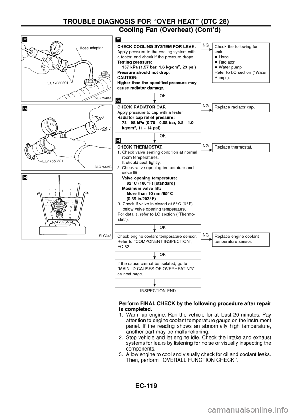
CHECK COOLING SYSTEM FOR LEAK.
Apply pressure to the cooling system with
a tester, and check if the pressure drops.
Testing pressure:
157 kPa (1.57 bar, 1.6 kg/cm
2, 23 psi)
Pressure should not drop.
CAUTION:
Higher than the speci®ed pressure may
cause radiator damage.
OK
cNG
Check the following for
leak.
+Hose
+Radiator
+Water pump
Refer to LC section (``Water
Pump'').
CHECK RADIATOR CAP.
Apply pressure to cap with a tester.
Radiator cap relief pressure:
78 - 98 kPa (0.78 - 0.98 bar, 0.8 - 1.0
kg/cm
2, 11 - 14 psi)
OK
cNG
Replace radiator cap.
CHECK THERMOSTAT.
1. Check valve seating condition at normal
room temperatures.
It should seat tightly.
2. Check valve opening temperature and
valve lift.
Valve opening temperature:
82ÉC (180ÉF) [standard]
Maximum valve lift:
More than 10 mm/95ÉC
(0.39 in/203ÉF)
3. Check if valve is closed at 5ÉC (9ÉF)
below valve opening temperature.
For details, refer to LC section (``Thermo-
stat'').
OK
cNG
Replace thermostat.
Check engine coolant temperature sensor.
Refer to ``COMPONENT INSPECTION'',
EC-82.
OK
cNG
Replace engine coolant
temperature sensor.
If the cause cannot be isolated, go to
``MAIN 12 CAUSES OF OVERHEATING''
on next page.
INSPECTION END
Perform FINAL CHECK by the following procedure after repair
is completed.
1. Warm up engine. Run the vehicle for at least 20 minutes. Pay
attention to engine coolant temperature gauge on the instrument
panel. If the reading shows an abnormally high temperature,
another part may be malfunctioning.
2. Stop vehicle and let engine idle. Check the intake and exhaust
systems for leaks by listening for noise or visually inspecting the
components.
3. Allow engine to cool and visually check for oil and coolant leaks.
Then, perform ``OVERALL FUNCTION CHECK''.
SLC754AA
SLC755AB
SLC343
.
.
.
.
.
TROUBLE DIAGNOSIS FOR ``OVER HEAT'' (DTC 28)
Cooling Fan (Overheat) (Cont'd)
EC-119
Page 122 of 192
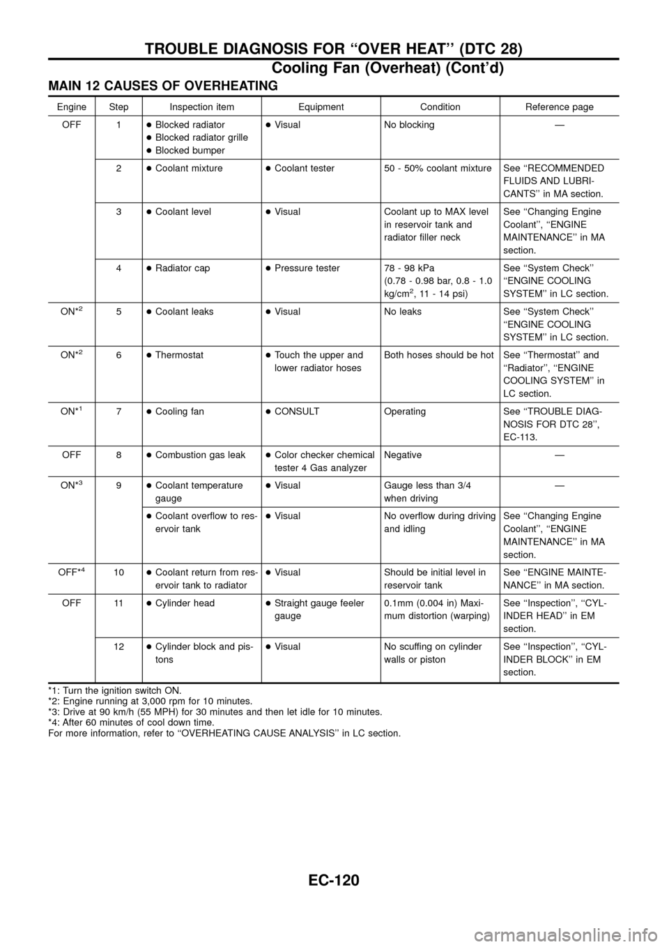
MAIN 12 CAUSES OF OVERHEATING
Engine Step Inspection item Equipment Condition Reference page
OFF 1+Blocked radiator
+Blocked radiator grille
+Blocked bumper+Visual No blocking Ð
2+Coolant mixture+Coolant tester 50 - 50% coolant mixture See ``RECOMMENDED
FLUIDS AND LUBRI-
CANTS'' in MA section.
3+Coolant level+Visual Coolant up to MAX level
in reservoir tank and
radiator ®ller neckSee ``Changing Engine
Coolant'', ``ENGINE
MAINTENANCE'' in MA
section.
4+Radiator cap+Pressure tester 78 - 98 kPa
(0.78 - 0.98 bar, 0.8 - 1.0
kg/cm
2, 11 - 14 psi)See ``System Check''
``ENGINE COOLING
SYSTEM'' in LC section.
ON*
25+Coolant leaks+Visual No leaks See ``System Check''
``ENGINE COOLING
SYSTEM'' in LC section.
ON*
26+Thermostat+Touch the upper and
lower radiator hosesBoth hoses should be hot See ``Thermostat'' and
``Radiator'', ``ENGINE
COOLING SYSTEM'' in
LC section.
ON*
17+Cooling fan+CONSULT Operating See ``TROUBLE DIAG-
NOSIS FOR DTC 28'',
EC-113.
OFF 8+Combustion gas leak+Color checker chemical
tester 4 Gas analyzerNegative Ð
ON*
39+Coolant temperature
gauge+Visual Gauge less than 3/4
when drivingÐ
+Coolant over¯ow to res-
ervoir tank+Visual No over¯ow during driving
and idlingSee ``Changing Engine
Coolant'', ``ENGINE
MAINTENANCE'' in MA
section.
OFF*
410+Coolant return from res-
ervoir tank to radiator+Visual Should be initial level in
reservoir tankSee ``ENGINE MAINTE-
NANCE'' in MA section.
OFF 11+Cylinder head+Straight gauge feeler
gauge0.1mm (0.004 in) Maxi-
mum distortion (warping)See ``Inspection'', ``CYL-
INDER HEAD'' in EM
section.
12+Cylinder block and pis-
tons+Visual No scuffing on cylinder
walls or pistonSee ``Inspection'', ``CYL-
INDER BLOCK'' in EM
section.
*1: Turn the ignition switch ON.
*2: Engine running at 3,000 rpm for 10 minutes.
*3: Drive at 90 km/h (55 MPH) for 30 minutes and then let idle for 10 minutes.
*4: After 60 minutes of cool down time.
For more information, refer to ``OVERHEATING CAUSE ANALYSIS'' in LC section.
TROUBLE DIAGNOSIS FOR ``OVER HEAT'' (DTC 28)
Cooling Fan (Overheat) (Cont'd)
EC-120
Page 137 of 192
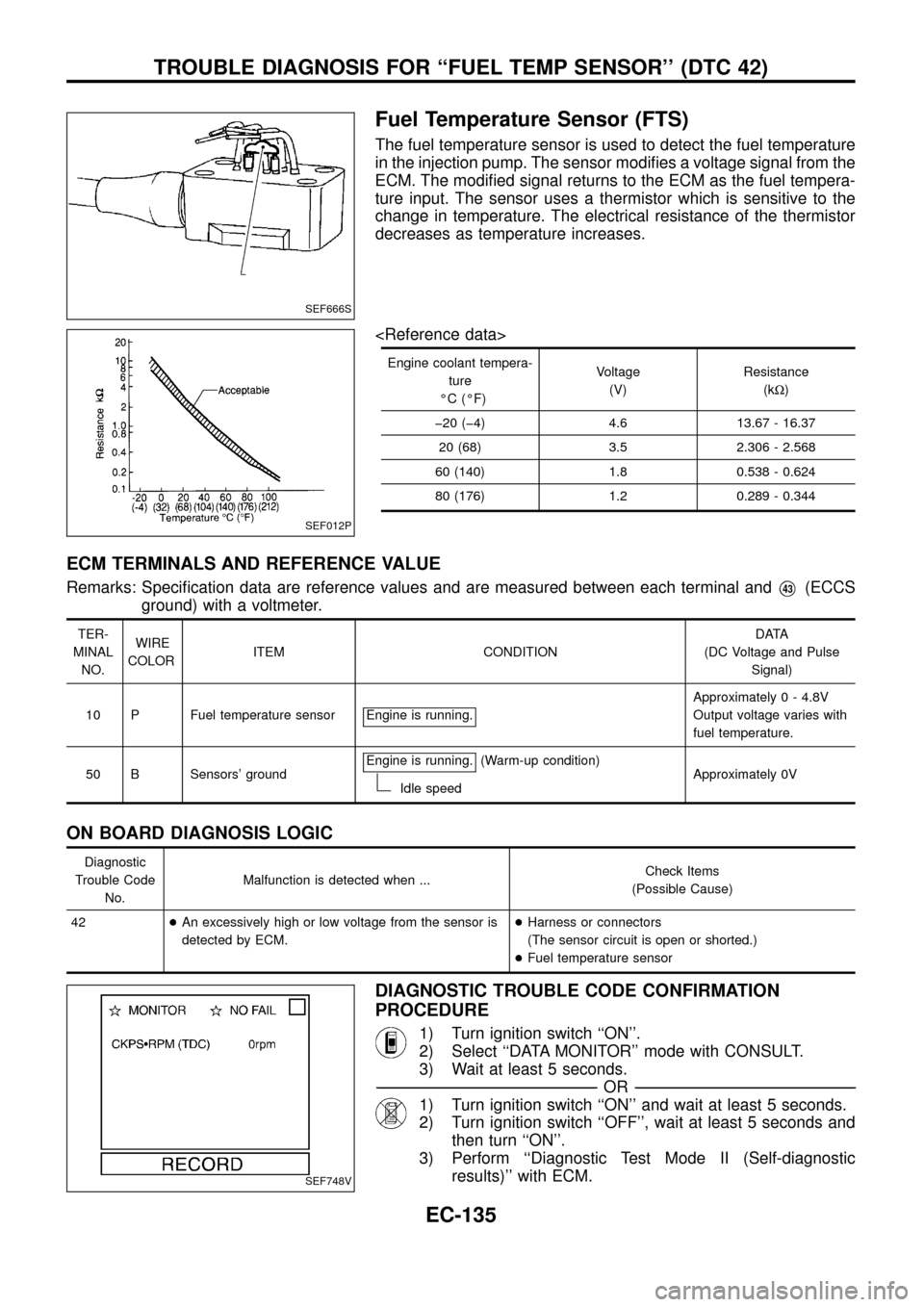
Fuel Temperature Sensor (FTS)
The fuel temperature sensor is used to detect the fuel temperature
in the injection pump. The sensor modi®es a voltage signal from the
ECM. The modi®ed signal returns to the ECM as the fuel tempera-
ture input. The sensor uses a thermistor which is sensitive to the
change in temperature. The electrical resistance of the thermistor
decreases as temperature increases.
Engine coolant tempera-
ture
ÉC (ÉF)Voltage
(V)Resistance
(kW)
þ20 (þ4) 4.6 13.67 - 16.37
20 (68) 3.5 2.306 - 2.568
60 (140) 1.8 0.538 - 0.624
80 (176) 1.2 0.289 - 0.344
ECM TERMINALS AND REFERENCE VALUE
Remarks: Speci®cation data are reference values and are measured between each terminal andV43(ECCS
ground) with a voltmeter.
TER-
MINAL
NO.WIRE
COLORITEM CONDITIONDATA
(DC Voltage and Pulse
Signal)
10 P Fuel temperature sensor Engine is running.
Approximately 0 - 4.8V
Output voltage varies with
fuel temperature.
50 B Sensors' groundEngine is running.
(Warm-up condition)
Idle speedApproximately 0V
ON BOARD DIAGNOSIS LOGIC
Diagnostic
Trouble Code
No.Malfunction is detected when ...Check Items
(Possible Cause)
42+An excessively high or low voltage from the sensor is
detected by ECM.+Harness or connectors
(The sensor circuit is open or shorted.)
+Fuel temperature sensor
DIAGNOSTIC TROUBLE CODE CONFIRMATION
PROCEDURE
1) Turn ignition switch ``ON''.
2) Select ``DATA MONITOR'' mode with CONSULT.
3) Wait at least 5 seconds.
-------------------------------------------------------------------------------------------------------------------------------------------------------------------------------------------------------------------------------------------------------OR-------------------------------------------------------------------------------------------------------------------------------------------------------------------------------------------------------------------------------------------------------
1) Turn ignition switch ``ON'' and wait at least 5 seconds.
2) Turn ignition switch ``OFF'', wait at least 5 seconds and
then turn ``ON''.
3) Perform ``Diagnostic Test Mode II (Self-diagnostic
results)'' with ECM.
SEF666S
SEF012P
SEF748V
TROUBLE DIAGNOSIS FOR ``FUEL TEMP SENSOR'' (DTC 42)
EC-135