1998 NISSAN PATROL timing
[x] Cancel search: timingPage 39 of 192
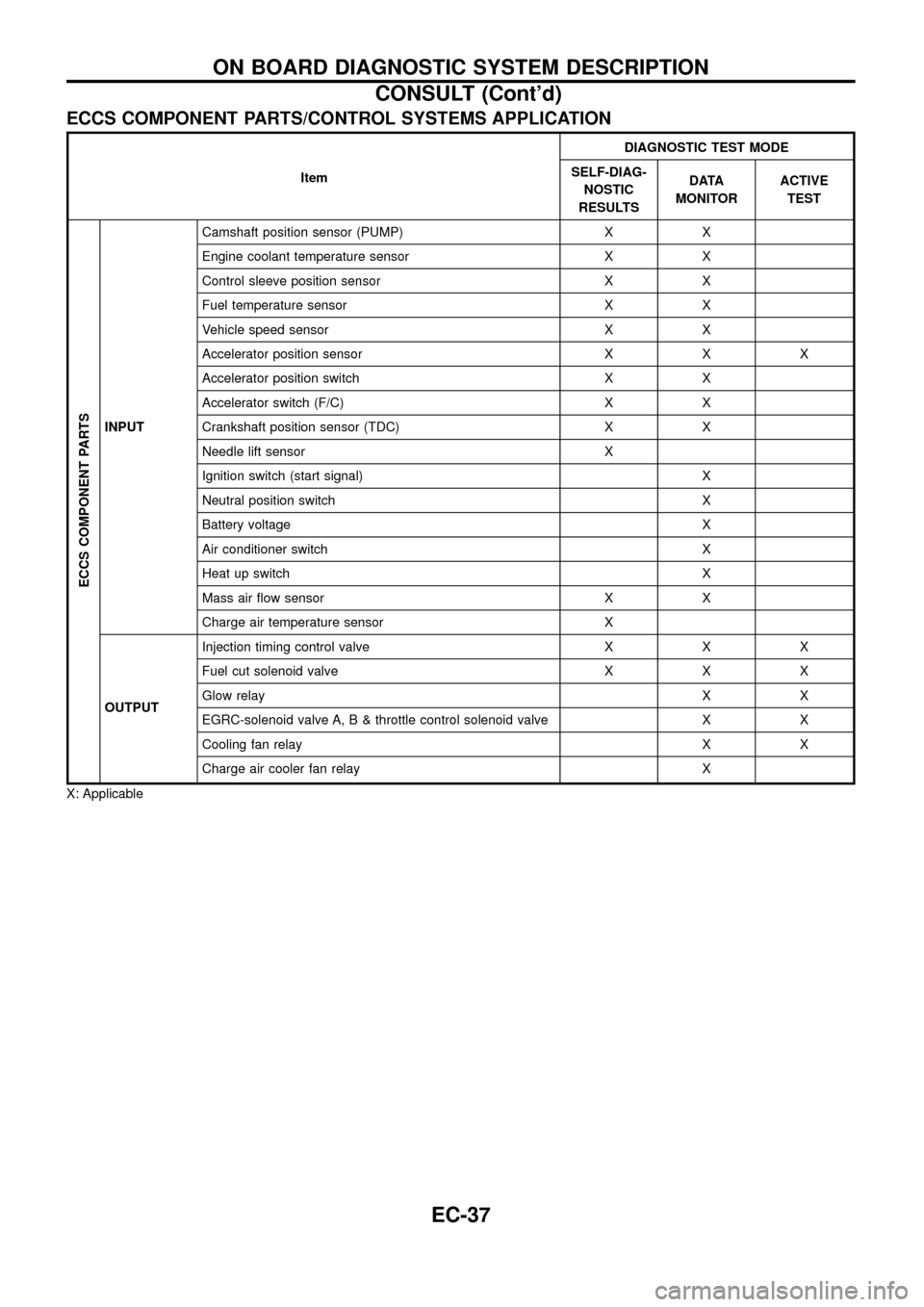
ECCS COMPONENT PARTS/CONTROL SYSTEMS APPLICATION
ItemDIAGNOSTIC TEST MODE
SELF-DIAG-
NOSTIC
RESULTSDATA
MONITORACTIVE
TEST
ECCS COMPONENT PARTS
INPUTCamshaft position sensor (PUMP) X X
Engine coolant temperature sensor X X
Control sleeve position sensor X X
Fuel temperature sensor X X
Vehicle speed sensor X X
Accelerator position sensor X X X
Accelerator position switch X X
Accelerator switch (F/C) X X
Crankshaft position sensor (TDC) X X
Needle lift sensor X
Ignition switch (start signal) X
Neutral position switch X
Battery voltage X
Air conditioner switch X
Heat up switch X
Mass air ¯ow sensor X X
Charge air temperature sensor X
OUTPUTInjection timing control valve X X X
Fuel cut solenoid valve X X X
Glow relayXX
EGRC-solenoid valve A, B & throttle control solenoid valve X X
Cooling fan relay X X
Charge air cooler fan relay X
X: Applicable
ON BOARD DIAGNOSTIC SYSTEM DESCRIPTION
CONSULT (Cont'd)
EC-37
Page 41 of 192
![NISSAN PATROL 1998 Y61 / 5.G Engine Control Workshop Manual Monitored item
[Unit]ECM
input
signalsMain
signalsDescription Remarks
AIR COND SIG
[ON/OFF]
jj
+Indicates [ON/OFF] condition of the air
conditioner switch as determined by the
air conditioner signal.
NISSAN PATROL 1998 Y61 / 5.G Engine Control Workshop Manual Monitored item
[Unit]ECM
input
signalsMain
signalsDescription Remarks
AIR COND SIG
[ON/OFF]
jj
+Indicates [ON/OFF] condition of the air
conditioner switch as determined by the
air conditioner signal.](/manual-img/5/617/w960_617-40.png)
Monitored item
[Unit]ECM
input
signalsMain
signalsDescription Remarks
AIR COND SIG
[ON/OFF]
jj
+Indicates [ON/OFF] condition of the air
conditioner switch as determined by the
air conditioner signal.
IGN SW
[ON/OFF]
jj+Indicates [ON/OFF] condition from igni-
tion switch signal.
MAS AIR/FL SE [V]
jj+The signal voltage of the mass air ¯ow
sensor is displayed.+When the engine is stopped, a certain
value is indicated.
ACT INJ TIMG [É]
jj
+The actual injection timing angle deter-
mined by the ECM (an approximate
average angle between injection start
and end from TDC) is displayed.
INJ TIMG C/V [%]+Indicates the duty ratio of fuel injection
timing control valve.
DECELER F/CUT
[ON/OFF]
j
+Indicates [ON/OFF] condition from decel-
eration fuel cut signal.+When the accelerator pedal is released
quickly with engine speed at 3,000 rpm
or more, ``ON'' is displayed.
FUEL CUT S/V
[ON/OFF]
j
+The control condition of the fuel cut sole-
noid valve (determined by ECM accord-
ing to the input signal) is indicted.
+OFF ... Fuel cut solenoid valve is not
operating.
ON ... Fuel cut solenoid valve is operat-
ing.+When the fuel cut solenoid valve is not
operating, fuel is not supplied to injection
nozzles.
GLOW RLY [ON/OFF]
j
+The glow relay control condition (deter-
mined by ECM according to the input
signal) is displayed.
COOLING FAN
[LOW/HI/OFF]
j
+Indicates the control condition of the
cooling fans (determined by ECM
according to the input signal).
+LOW ... Operates at low speed.
HI ... Operates at high speed.
OFF ... Stopped.
I/C FAN RLY
[ON/OFF]
j
+Indicates the control condition of the
charge air cooler fan (determined by
ECM according to the input signals).
EGRC SOL/V A
[ON/OFF]+The control condition of the EGRC-sole-
noid valve A (determined by ECM
according to the input signal) is indi-
cated.
+OFF ... EGRC-solenoid valve A is not
operating.
ON ... EGRC-solenoid valve A is operat-
ing.
EGRC SOL/V B
[ON/OFF]+The control condition of the EGRC-sole-
noid valve B (determined by ECM
according to the input signal) is indi-
cated.
+OFF ... EGRC-solenoid valve B is not
operating.
ON ... EGRC-solenoid valve B is operat-
ing.
THROT RLY
[ON/OFF]+The control condition of the throttle con-
trol solenoid valve (determined by ECM
according to the input signal) is indi-
cated.
+OFF ... Throttle control solenoid valve is
not operating.
ON ... Throttle control solenoid valve is
operating.
ON BOARD DIAGNOSTIC SYSTEM DESCRIPTION
CONSULT (Cont'd)
EC-39
Page 42 of 192
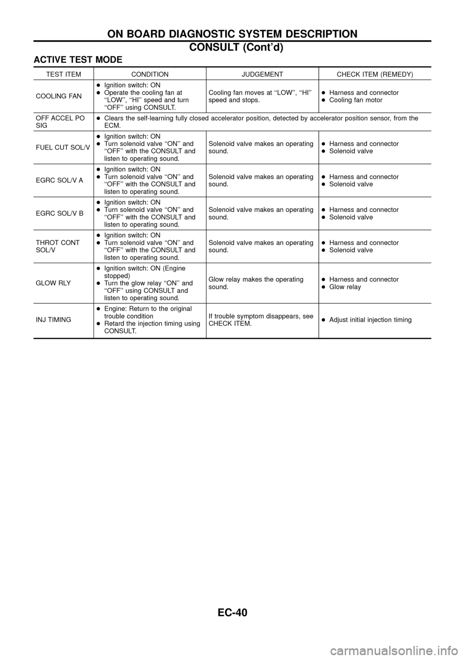
ACTIVE TEST MODE
TEST ITEM CONDITION JUDGEMENT CHECK ITEM (REMEDY)
COOLING FAN+Ignition switch: ON
+Operate the cooling fan at
``LOW'', ``HI'' speed and turn
``OFF'' using CONSULT.Cooling fan moves at ``LOW'', ``HI''
speed and stops.+Harness and connector
+Cooling fan motor
OFF ACCEL PO
SIG+Clears the self-learning fully closed accelerator position, detected by accelerator position sensor, from the
ECM.
FUEL CUT SOL/V+Ignition switch: ON
+Turn solenoid valve ``ON'' and
``OFF'' with the CONSULT and
listen to operating sound.Solenoid valve makes an operating
sound.+Harness and connector
+Solenoid valve
EGRC SOL/V A+Ignition switch: ON
+Turn solenoid valve ``ON'' and
``OFF'' with the CONSULT and
listen to operating sound.Solenoid valve makes an operating
sound.+Harness and connector
+Solenoid valve
EGRC SOL/V B+Ignition switch: ON
+Turn solenoid valve ``ON'' and
``OFF'' with the CONSULT and
listen to operating sound.Solenoid valve makes an operating
sound.+Harness and connector
+Solenoid valve
THROT CONT
SOL/V+Ignition switch: ON
+Turn solenoid valve ``ON'' and
``OFF'' with the CONSULT and
listen to operating sound.Solenoid valve makes an operating
sound.+Harness and connector
+Solenoid valve
GLOW RLY+Ignition switch: ON (Engine
stopped)
+Turn the glow relay ``ON'' and
``OFF'' using CONSULT and
listen to operating sound.Glow relay makes the operating
sound.+Harness and connector
+Glow relay
INJ TIMING+Engine: Return to the original
trouble condition
+Retard the injection timing using
CONSULT.If trouble symptom disappears, see
CHECK ITEM.+Adjust initial injection timing
ON BOARD DIAGNOSTIC SYSTEM DESCRIPTION
CONSULT (Cont'd)
EC-40
Page 44 of 192
Introduction
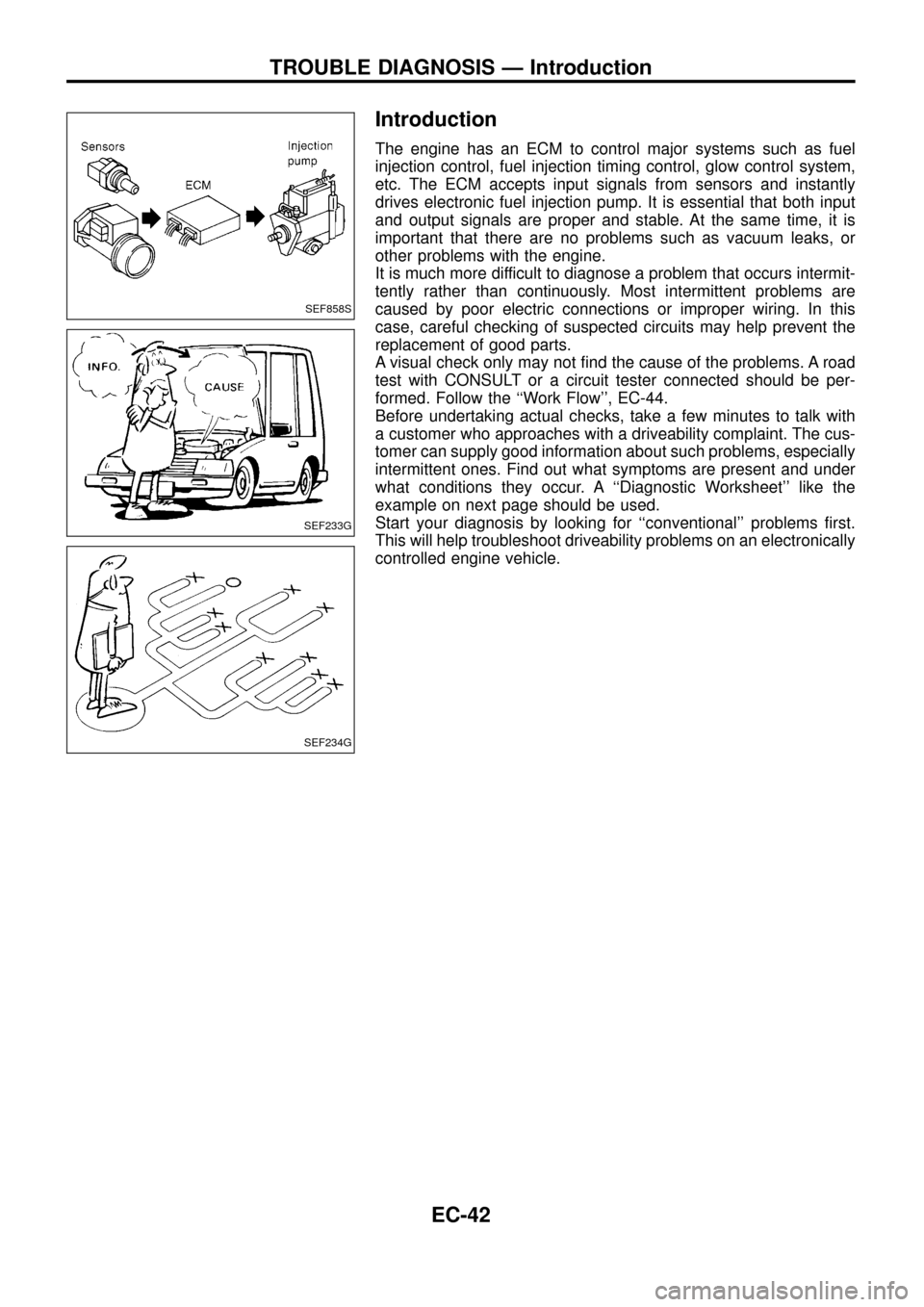
The engine has an ECM to control major systems such as fuel
injection control, fuel injection timing control, glow control system,
etc. The ECM accepts input signals from sensors and instantly
drives electronic fuel injection pump. It is essential that both input
and output signals are proper and stable. At the same time, it is
important that there are no problems such as vacuum leaks, or
other problems with the engine.
It is much more difficult to diagnose a problem that occurs intermit-
tently rather than continuously. Most intermittent problems are
caused by poor electric connections or improper wiring. In this
case, careful checking of suspected circuits may help prevent the
replacement of good parts.
A visual check only may not ®nd the cause of the problems. A road
test with CONSULT or a circuit tester connected should be per-
formed. Follow the ``Work Flow'', EC-44.
Before undertaking actual checks, take a few minutes to talk with
a customer who approaches with a driveability complaint. The cus-
tomer can supply good information about such problems, especially
intermittent ones. Find out what symptoms are present and under
what conditions they occur. A ``Diagnostic Worksheet'' like the
example on next page should be used.
Start your diagnosis by looking for ``conventional'' problems ®rst.
This will help troubleshoot driveability problems on an electronically
controlled engine vehicle.
SEF858S
SEF233G
SEF234G
TROUBLE DIAGNOSIS Ð Introduction
EC-42
Page 49 of 192
jA
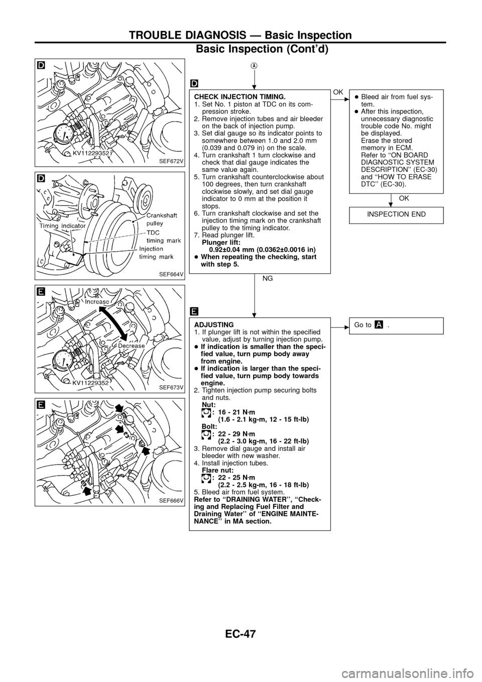
CHECK INJECTION TIMING.
1. Set No. 1 piston at TDC on its com-
pression stroke.
2. Remove injection tubes and air bleeder
on the back of injection pump.
3. Set dial gauge so its indicator points to
somewhere between 1.0 and 2.0 mm
(0.039 and 0.079 in) on the scale.
4. Turn crankshaft 1 turn clockwise and
check that dial gauge indicates the
same value again.
5. Turn crankshaft counterclockwise about
100 degrees, then turn crankshaft
clockwise slowly, and set dial gauge
indicator to 0 mm at the position it
stops.
6. Turn crankshaft clockwise and set the
injection timing mark on the crankshaft
pulley to the timing indicator.
7. Read plunger lift.
Plunger lift:
0.92 0.04 mm (0.0362 0.0016 in)
+When repeating the checking, start
with step 5.
NG
cOK
+Bleed air from fuel sys-
tem.
+After this inspection,
unnecessary diagnostic
trouble code No. might
be displayed.
Erase the stored
memory in ECM.
Refer to ``ON BOARD
DIAGNOSTIC SYSTEM
DESCRIPTION'' (EC-30)
and ``HOW TO ERASE
DTC'' (EC-30).
OK
INSPECTION END
ADJUSTING
1. If plunger lift is not within the speci®ed
value, adjust by turning injection pump.
+If indication is smaller than the speci-
®ed value, turn pump body away
from engine.
+If indication is larger than the speci-
®ed value, turn pump body towards
engine.
2. Tighten injection pump securing bolts
and nuts.
Nut:
: 16-21Nzm
(1.6 - 2.1 kg-m, 12 - 15 ft-lb)
Bolt:
: 22-29Nzm
(2.2 - 3.0 kg-m, 16 - 22 ft-lb)
3. Remove dial gauge and install air
bleeder with new washer.
4. Install injection tubes.
Flare nut:
: 22-25Nzm
(2.2 - 2.5 kg-m, 16 - 18 ft-lb)
5. Bleed air from fuel system.
Refer to ``DRAINING WATER'', ``Check-
ing and Replacing Fuel Filter and
Draining Water'' of ``ENGINE MAINTE-
NANCE'' in MA section.
cGo to.
SEF672V
SEF664V
SEF673V
SEF666V
.
.
.
TROUBLE DIAGNOSIS Ð Basic Inspection
Basic Inspection (Cont'd)
EC-47
Page 50 of 192
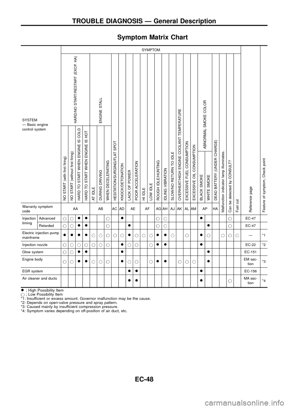
Symptom Matrix Chart
SYSTEM
Ð Basic engine
control systemSYMPTOM
Reference page
Feature of symptom, Check pointHARD/NO START/RESTART (EXCP. HA)
ENGINE STALL
HESITATION/SURGING/FLAT SPOT
KNOCK/DETONATION
LACK OF POWER
POOR ACCELERATION
HI IDLE
LOW IDLE
ROUGH IDLE/HUNTING
IDLING VIBRATION
SLOW/NO RETURN TO IDLE
OVERHEAT/HIGH ENGINE COOLANT TEMPERATURE
EXCESSIVE FUEL CONSUMPTION
EXCESSIVE OIL CONSUMPTION
ABNORMAL SMOKE COLOR
DEAD BATTERY (UNDER CHARGE)
Malfunction indicator lamp illuminates.
Can be detected by CONSULT?
Fuel cutNO START (with ®rst ®ring)
NO START (without ®rst ®ring)
HARD TO START WHEN ENGINE IS COLD
HARD TO START WHEN ENGINE IS HOT
AT IDLE
DURING DRIVING
WHEN DECELERATING
BLACK SMOKE
WHITE SMOKEWarranty symptom
codeAA AB AC AD AE AF AG AH AJ AK AL AM AP HA
Injection
timingAdvancedjj
++j+jj+jEC-47
Retardedjj
++j+jj+jEC-47
Electric injection pump
mainframe
++++jjjjj+jjj++jj+j jjjÐ*1
Injection nozzlejjjjjjj
+jj j++ +EC-22 *2
Glow systemjj
++ + +EC-151
Engine body
jj
++jjj+jj j++jjj+EM sec-
tion*3
EGR system
++ +EC-156
Air cleaner and ducts
++ +jMA sec-
tion*4
+; High Possibility Item
j; Low Possibility Item
*1: Insufficient or excess amount. Governor malfunction may be the cause.
*2: Depends on open-valve pressure and spray pattern.
*3: Caused mainly by insufficient compression pressure.
*4: Symptom varies depending on off-position of air duct, etc.
TROUBLE DIAGNOSIS Ð General Description
EC-48
Page 51 of 192
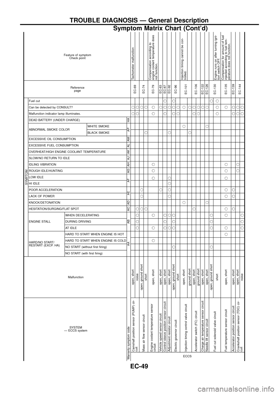
SYSTEM
Ð ECCS systemMalfunction
SYMPTOM
Reference
page Feature of symptom
Check point
HARD/NO START/
RESTART (EXCP. HA) ENGINE STALL HESITATION/SURGING/FLAT SPOT KNOCK/DETONATION
LACK OF POWER
POOR ACCELERATION
HI IDLE
LOW IDLE
ROUGH IDLE/HUNTING
IDLING VIBRATION
SLOW/NO RETURN TO IDLE
OVERHEAT/HIGH ENGINE COOLANT TEMPERATURE
EXCESSIVE FUEL CONSUMPTION
EXCESSIVE OIL CONSUMPTION ABNORMAL SMOKE COLOR
DEAD BATTERY (UNDER CHARGE) Malfunction indicator lamp illuminates.
Can be detected by CONSULT?
Fuel cut
NO START (with ®rst ®ring) NO START (without ®rst ®ring)
HARD TO START WHEN ENGINE IS COLD
HARD TO START WHEN ENGINE IS HOT
AT IDLE
DURING DRIVING
WHEN DECELERATINGBLACK SMOKE WHITE SMOKE
Warranty symptom code AA AB AC AD AE AF AG AH AJ AK AL AM AP HAECCS
Camshaft position sensor (PUMP) cir-
cuitopen, shortjj
EC-69Tachometer malfunction
noisejjjj jj
Mass air ¯ow sensor circuitopen, ground shortjjj j
EC-74
shortjjj
Engine coolant temperature sensor
circuitopen, shortjjj jjj jjEC-79Compensation according to
engine coolant temperature does
not function.
Vehicle speed sensor circuit open, shortjjEC-83
Control sleeve position sensor circuit open, shortjjjjjjEC-87
Adjustment resistor circuit open, shortj j jjjj j jEC-92
Electric governor circuitopen, ground shortj jjjjjj
EC-96
shortjj
Injection timing control valve circuitopen, shortjjj
EC-101Injection timing cannot be con-
trolled.
ground shortjj
Accelerator switch (FC) circuitopen, shortjjj
EC-106
ground shortjj
Charge air temperature sensor circuit open, shortjEC-122
Needle lift sensor circuit open, shortjjjEC-126
Fuel cut solenoid valve circuitopen, ground shortj jjjj
EC-130
shortjjjEngine runs on after turning igni-
tion switch OFF.
Fuel temperature sensor circuit open, shortjj jj jj j jj jEC-135Compensation for amount of fuel
injected according to fuel tem-
perature does not function.
Accelerator position sensor circuit open, shortjjj jjEC-139
Crankshaft position sensor (TDC) cir-
cuitopen, shortjj jj
EC-144
noisejjjjj
TROUBLE DIAGNOSIS Ð General Description
Symptom Matrix Chart (Cont'd)
EC-49
Page 63 of 192
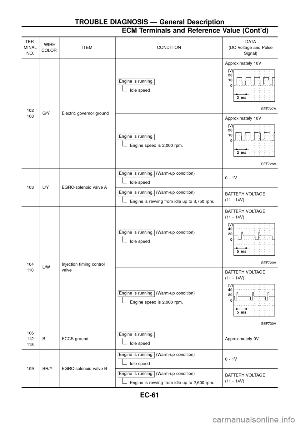
TER-
MINAL
NO.WIRE
COLORITEM CONDITIONDATA
(DC Voltage and Pulse
Signal)
102
108G/Y Electric governor groundEngine is running.
Idle speedApproximately 10V
SEF727V
Engine is running.
Engine speed is 2,000 rpm.Approximately 10V
SEF728V
103 L/Y EGRC-solenoid valve AEngine is running.
(Warm-up condition)
Idle speed0-1V
Engine is running.
(Warm-up condition)
Engine is revving from idle up to 3,750 rpm.BATTERY VOLTAGE
(11 - 14V)
104
11 0L/WInjection timing control
valveEngine is running.
(Warm-up condition)
Idle speedBATTERY VOLTAGE
(11 - 14V)
SEF729V
Engine is running.(Warm-up condition)
Engine speed is 2,000 rpm.BATTERY VOLTAGE
(11 - 14V)
SEF730V
106
11 2
11 8B ECCS groundEngine is running.
Idle speedApproximately 0V
109 BR/Y EGRC-solenoid valve BEngine is running.
(Warm-up condition)
Idle speed0-1V
Engine is running.
(Warm-up condition)
Engine is revving from idle up to 2,600 rpm.BATTERY VOLTAGE
(11 - 14V)
TROUBLE DIAGNOSIS Ð General Description
ECM Terminals and Reference Value (Cont'd)
EC-61