Page 163 of 192
jB
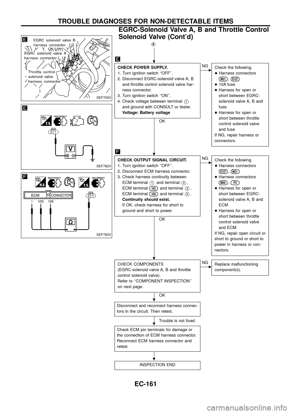
CHECK POWER SUPPLY.
1. Turn ignition switch ``OFF''.
2. Disconnect EGRC-solenoid valve A, B
and throttle control solenoid valve har-
ness connector.
3. Turn ignition switch ``ON''.
4. Check voltage between terminal
V1
and ground with CONSULT or tester.
Voltage: Battery voltage
OK
cNG
Check the following.
+Harness connectors
M21,E127
+10A fuse
+Harness for open or
short between EGRC-
solenoid valve A, B and
fuse
+Harness for open or
short between throttle
control solenoid valve
and fuse
If NG, repair harness or
connectors.
CHECK OUTPUT SIGNAL CIRCUIT.
1. Turn ignition switch ``OFF''.
2. Disconnect ECM harness connector.
3. Check harness continuity between
ECM terminal
V1and terminalV2,
ECM terminal
103and terminalV2,
ECM terminal
109and terminalV2.
Continuity should exist.
If OK, check harness for short to
ground and short to power.
OK
cNG
Check the following.
+Harness connectors
E127,M21
+Harness connectors
M50,F5
+Harness for open or
short between EGRC-
solenoid valve A, B and
ECM
+Harness for open or
short between throttle
control solenoid valve
and ECM
If NG, repair open circuit or
short to ground or short to
power in harness or con-
nectors.
CHECK COMPONENTS
(EGRC-solenoid valve A, B and throttle
control solenoid valve).
Refer to ``COMPONENT INSPECTION''
on next page.
OK
cNG
Replace malfunctioning
component(s).
Disconnect and reconnect harness connec-
tors in the circuit. Then retest.
Trouble is not ®xed.
Check ECM pin terminals for damage or
the connection of ECM harness connector.
Reconnect ECM harness connector and
retest.
INSPECTION END
SEF706V
SEF782V
SEF783V
.
.
.
.
.
.
TROUBLE DIAGNOSES FOR NON-DETECTABLE ITEMS
EGRC-Solenoid Valve A, B and Throttle Control
Solenoid Valve (Cont'd)
EC-161
Page 166 of 192
DIAGNOSTIC PROCEDURE
INSPECTION START
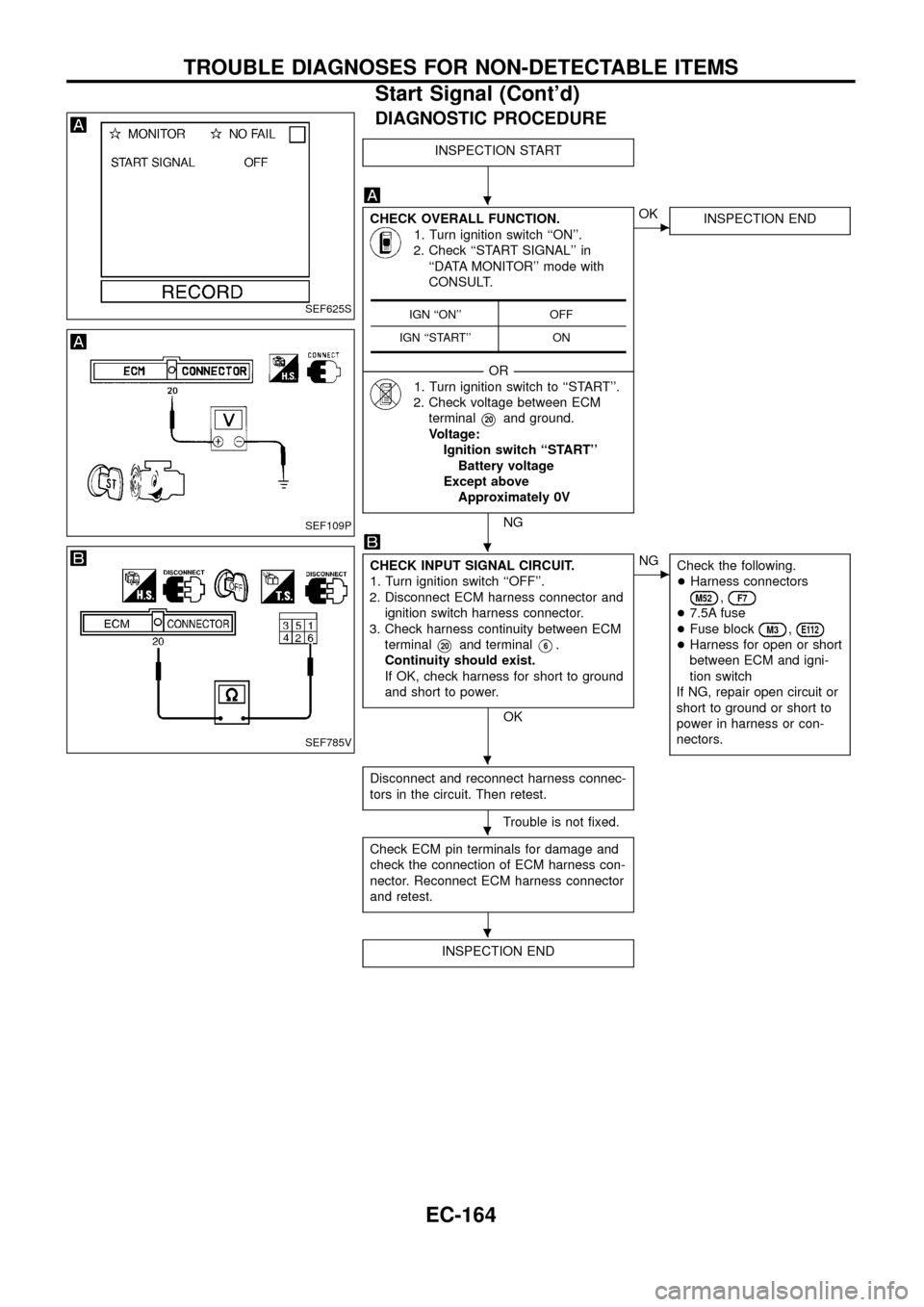
CHECK OVERALL FUNCTION.
1. Turn ignition switch ``ON''.
2. Check ``START SIGNAL'' in
``DATA MONITOR'' mode with
CONSULT.
--------------------------------------------------------------------------------------------------------------------------------------OR--------------------------------------------------------------------------------------------------------------------------------------
1. Turn ignition switch to ``START''.
2. Check voltage between ECM
terminal
V20and ground.
Voltage:
Ignition switch ``START''
Battery voltage
Except above
Approximately 0V
NG
cOK
INSPECTION END
CHECK INPUT SIGNAL CIRCUIT.
1. Turn ignition switch ``OFF''.
2. Disconnect ECM harness connector and
ignition switch harness connector.
3. Check harness continuity between ECM
terminal
V20and terminalV6.
Continuity should exist.
If OK, check harness for short to ground
and short to power.
OK
cNG
Check the following.
+Harness connectors
M52,F7
+7.5A fuse
+Fuse block
M3,E112
+Harness for open or short
between ECM and igni-
tion switch
If NG, repair open circuit or
short to ground or short to
power in harness or con-
nectors.
Disconnect and reconnect harness connec-
tors in the circuit. Then retest.
Trouble is not ®xed.
Check ECM pin terminals for damage and
check the connection of ECM harness con-
nector. Reconnect ECM harness connector
and retest.
INSPECTION END
IGN ``ON'' OFF
IGN ``START'' ONSEF625S
SEF109P
SEF785V
.
.
.
.
.
TROUBLE DIAGNOSES FOR NON-DETECTABLE ITEMS
Start Signal (Cont'd)
EC-164
Page 175 of 192
A/T models
INSPECTION START
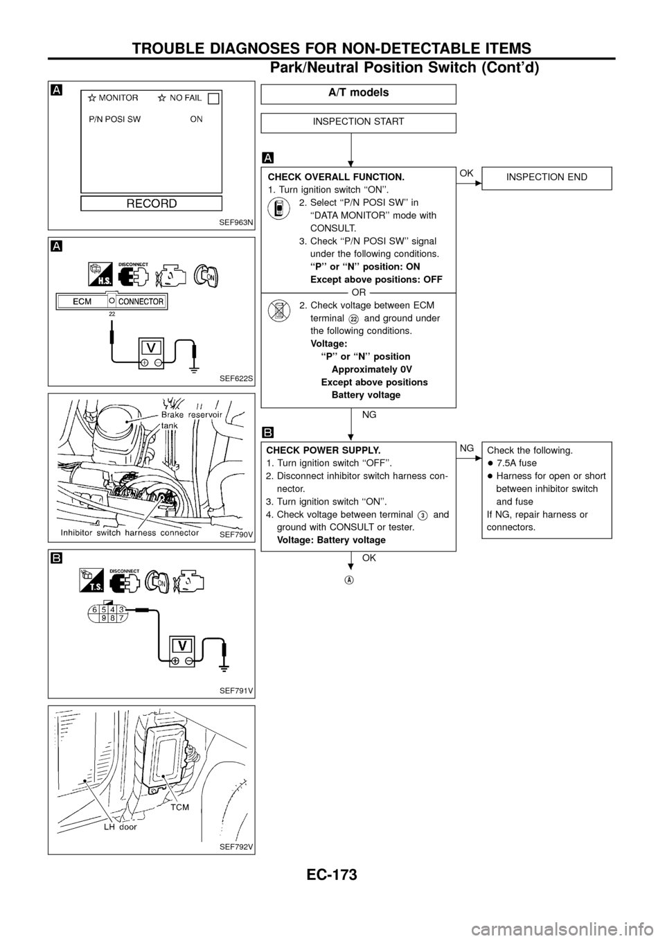
CHECK OVERALL FUNCTION.
1. Turn ignition switch ``ON''.
2. Select ``P/N POSI SW'' in
``DATA MONITOR'' mode with
CONSULT.
3. Check ``P/N POSI SW'' signal
under the following conditions.
``P'' or ``N'' position: ON
Except above positions: OFF
--------------------------------------------------------------------------------------------------------------------------------------OR--------------------------------------------------------------------------------------------------------------------------------------
2. Check voltage between ECM
terminal
V22and ground under
the following conditions.
Voltage:
``P'' or ``N'' position
Approximately 0V
Except above positions
Battery voltage
NG
cOK
INSPECTION END
CHECK POWER SUPPLY.
1. Turn ignition switch ``OFF''.
2. Disconnect inhibitor switch harness con-
nector.
3. Turn ignition switch ``ON''.
4. Check voltage between terminal
V3and
ground with CONSULT or tester.
Voltage: Battery voltage
OK
cNG
Check the following.
+7.5A fuse
+Harness for open or short
between inhibitor switch
and fuse
If NG, repair harness or
connectors.
jA
SEF963N
SEF622S
SEF790V
SEF791V
SEF792V
.
.
.
TROUBLE DIAGNOSES FOR NON-DETECTABLE ITEMS
Park/Neutral Position Switch (Cont'd)
EC-173
Page 182 of 192
DIAGNOSTIC PROCEDURE
INSPECTION START
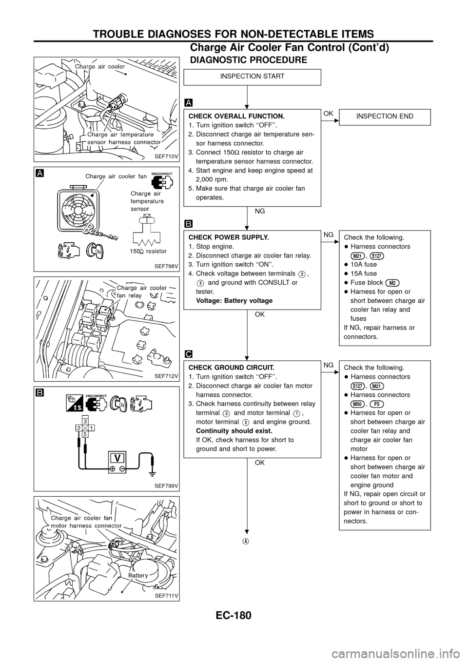
CHECK OVERALL FUNCTION.
1. Turn ignition switch ``OFF''.
2. Disconnect charge air temperature sen-
sor harness connector.
3. Connect 150Wresistor to charge air
temperature sensor harness connector.
4. Start engine and keep engine speed at
2,000 rpm.
5. Make sure that charge air cooler fan
operates.
NG
cOK
INSPECTION END
CHECK POWER SUPPLY.
1. Stop engine.
2. Disconnect charge air cooler fan relay.
3. Turn ignition switch ``ON''.
4. Check voltage between terminals
V2,
V5and ground with CONSULT or
tester.
Voltage: Battery voltage
OK
cNG
Check the following.
+Harness connectors
M21,E127
+10A fuse
+15A fuse
+Fuse block
M2
+Harness for open or
short between charge air
cooler fan relay and
fuses
If NG, repair harness or
connectors.
CHECK GROUND CIRCUIT.
1. Turn ignition switch ``OFF''.
2. Disconnect charge air cooler fan motor
harness connector.
3. Check harness continuity between relay
terminal
V3and motor terminalV1,
motor terminal
V2and engine ground.
Continuity should exist.
If OK, check harness for short to
ground and short to power.
OK
cNG
Check the following.
+Harness connectors
E127,M21
+Harness connectors
M50,F5
+Harness for open or
short between charge air
cooler fan relay and
charge air cooler fan
motor
+Harness for open or
short between charge air
cooler fan motor and
engine ground
If NG, repair open circuit or
short to ground or short to
power in harness or con-
nectors.
jA
SEF710V
SEF798V
SEF712V
SEF799V
SEF711V
.
.
.
.
TROUBLE DIAGNOSES FOR NON-DETECTABLE ITEMS
Charge Air Cooler Fan Control (Cont'd)
EC-180
Page 187 of 192
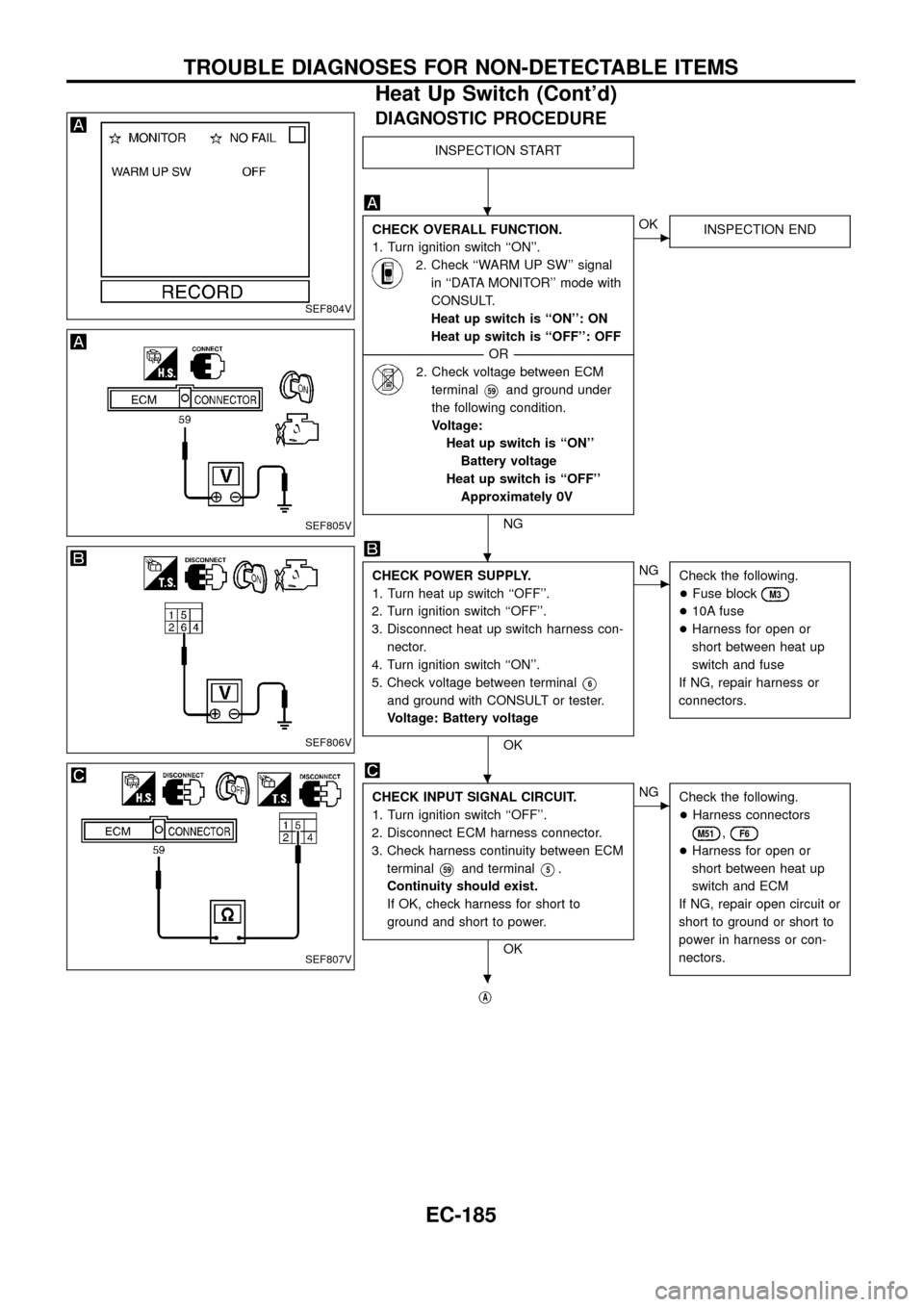
DIAGNOSTIC PROCEDURE
INSPECTION START
CHECK OVERALL FUNCTION.
1. Turn ignition switch ``ON''.
2. Check ``WARM UP SW'' signal
in ``DATA MONITOR'' mode with
CONSULT.
Heat up switch is ``ON'': ON
Heat up switch is ``OFF'': OFF
--------------------------------------------------------------------------------------------------------------------------------------OR--------------------------------------------------------------------------------------------------------------------------------------
2. Check voltage between ECM
terminal
V59and ground under
the following condition.
Voltage:
Heat up switch is ``ON''
Battery voltage
Heat up switch is ``OFF''
Approximately 0V
NG
cOK
INSPECTION END
CHECK POWER SUPPLY.
1. Turn heat up switch ``OFF''.
2. Turn ignition switch ``OFF''.
3. Disconnect heat up switch harness con-
nector.
4. Turn ignition switch ``ON''.
5. Check voltage between terminal
V6
and ground with CONSULT or tester.
Voltage: Battery voltage
OK
cNG
Check the following.
+Fuse block
M3
+10A fuse
+Harness for open or
short between heat up
switch and fuse
If NG, repair harness or
connectors.
CHECK INPUT SIGNAL CIRCUIT.
1. Turn ignition switch ``OFF''.
2. Disconnect ECM harness connector.
3. Check harness continuity between ECM
terminal
V59and terminalV5.
Continuity should exist.
If OK, check harness for short to
ground and short to power.
OK
cNG
Check the following.
+Harness connectors
M51,F6
+Harness for open or
short between heat up
switch and ECM
If NG, repair open circuit or
short to ground or short to
power in harness or con-
nectors.
jA
SEF804V
SEF805V
SEF806V
SEF807V
.
.
.
.
TROUBLE DIAGNOSES FOR NON-DETECTABLE ITEMS
Heat Up Switch (Cont'd)
EC-185