Page 43 of 326
2. Convert into speci®c gravity at 20ÉC (68ÉF).
Example:
+When electrolyte temperature is 35ÉC (95ÉF) and speci®c grav-
ity of electrolyte is 1.230, converted speci®c gravity at 20ÉC
(68ÉF) is 1.240.
+When electrolyte temperature is 0ÉC (32ÉF) and speci®c grav-
ity of electrolyte is 1.210, converted speci®c gravity at 20ÉC
(68ÉF) is 1.196.
SEL007Z
BATTERY
How to Handle Battery (Cont'd)
EL-39
Page 44 of 326

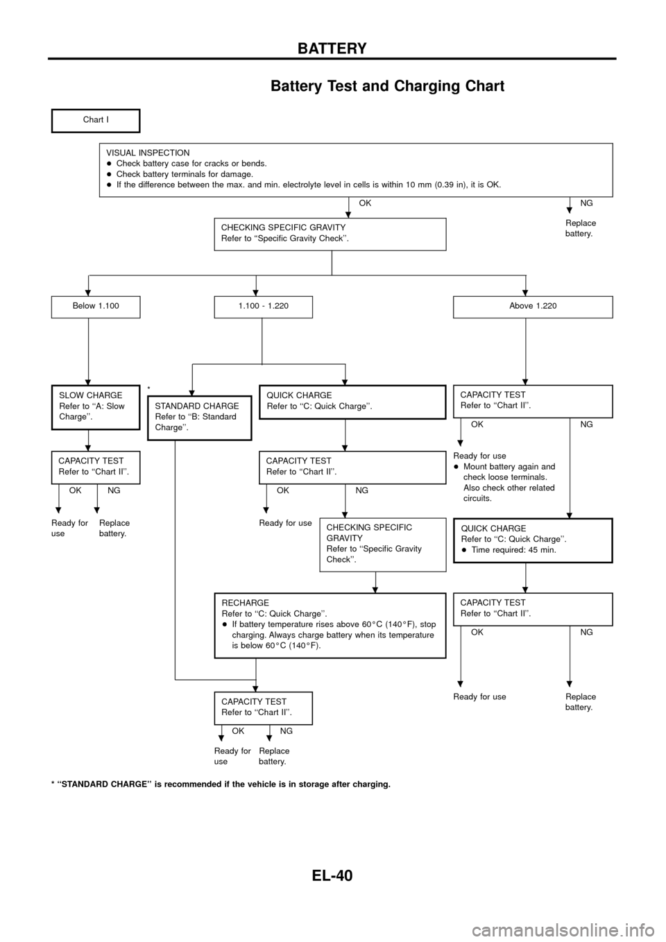
Battery Test and Charging Chart
Chart I
VISUAL INSPECTION
+Check battery case for cracks or bends.
+Check battery terminals for damage.
+If the difference between the max. and min. electrolyte level in cells is within 10 mm (0.39 in), it is OK.
OK NG
CHECKING SPECIFIC GRAVITY
Refer to ``Speci®c Gravity Check''.
Replace
battery.
Below 1.1001.100 - 1.220Above 1.220
SLOW CHARGE
Refer to ``A: Slow
Charge''.*
STANDARD CHARGE
Refer to ``B: Standard
Charge''.QUICK CHARGE
Refer to ``C: Quick Charge''.CAPACITY TEST
Refer to ``Chart II''.
OK NG
CAPACITY TEST
Refer to ``Chart II''.
OK NGCAPACITY TEST
Refer to ``Chart II''.OK NGReady for use
+Mount battery again and
check loose terminals.
Also check other related
circuits.
Ready for
useReplace
battery.Ready for use
CHECKING SPECIFIC
GRAVITY
Refer to ``Speci®c Gravity
Check''.
QUICK CHARGE
Refer to ``C: Quick Charge''.
+Time required: 45 min.
RECHARGE
Refer to ``C: Quick Charge''.
+If battery temperature rises above 60ÉC (140ÉF), stop
charging. Always charge battery when its temperature
is below 60ÉC (140ÉF).CAPACITY TEST
Refer to ``Chart II''.
OK NG
CAPACITY TEST
Refer to ``Chart II''.
OK NGReady for use Replace
battery.
Ready for
useReplace
battery.
* ``STANDARD CHARGE'' is recommended if the vehicle is in storage after charging.
..
...
....
...
.....
..
...
..
BATTERY
EL-40
Page 46 of 326

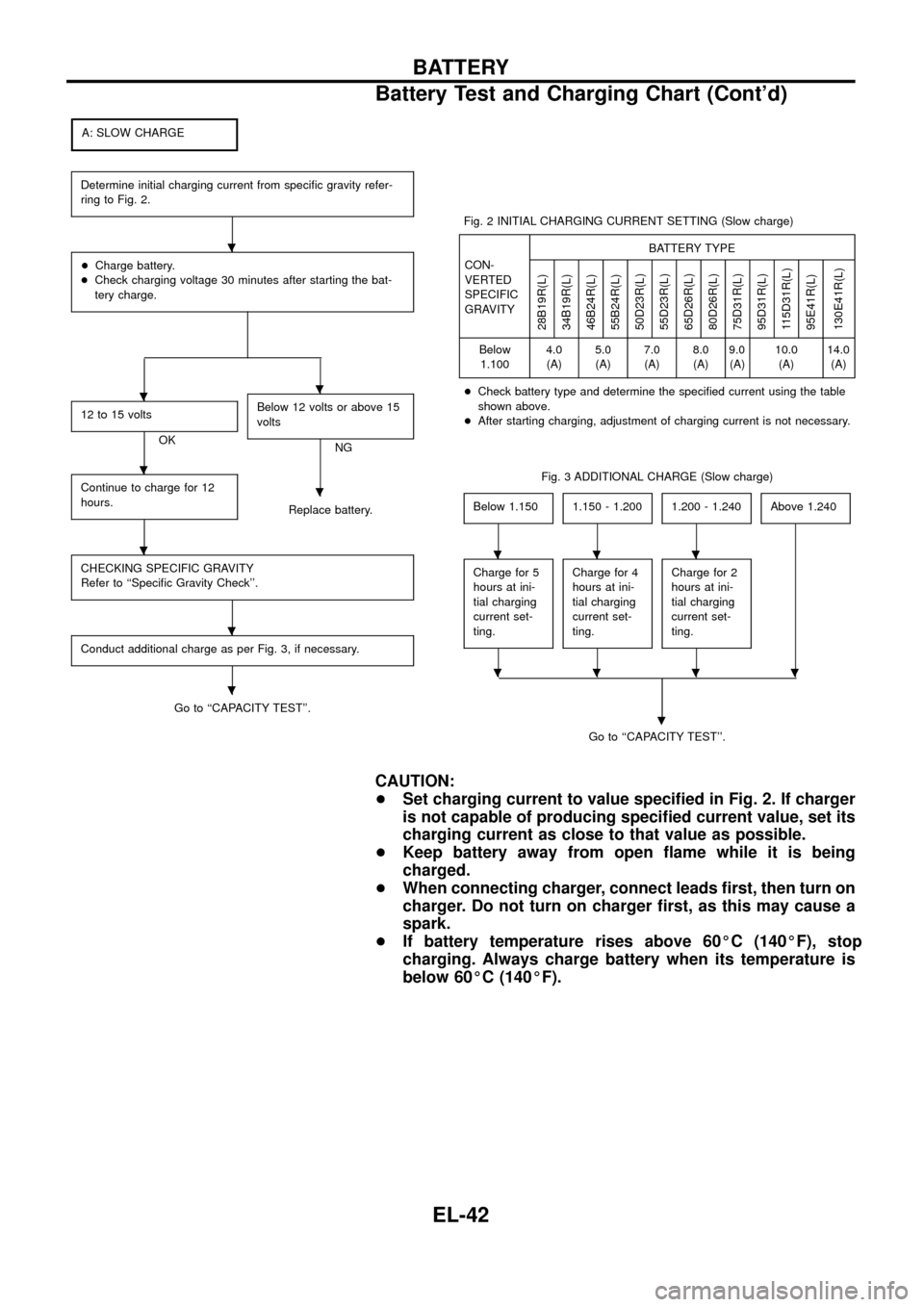
A: SLOW CHARGE
Determine initial charging current from speci®c gravity refer-
ring to Fig. 2.
+Charge battery.
+Check charging voltage 30 minutes after starting the bat-
tery charge.
12 to 15 volts
OKBelow 12 volts or above 15
voltsNG
Continue to charge for 12
hours.
Replace battery.
CHECKING SPECIFIC GRAVITY
Refer to ``Speci®c Gravity Check''.
Conduct additional charge as per Fig. 3, if necessary.
Go to ``CAPACITY TEST''.Fig. 2 INITIAL CHARGING CURRENT SETTING (Slow charge)
CON-
VERTED
SPECIFIC
GRAVITYBATTERY TYPE
28B19R(L)
34B19R(L)
46B24R(L)
55B24R(L)
50D23R(L)
55D23R(L)
65D26R(L)
80D26R(L)
75D31R(L)
95D31R(L)
115D31R(L)
95E41R(L)
130E41R(L)
Below
1.1004.0
(A)5.0
(A)7.0
(A)8.0
(A)9.0
(A)10.0
(A)14.0
(A)
+Check battery type and determine the speci®ed current using the table
shown above.
+After starting charging, adjustment of charging current is not necessary.
Fig. 3 ADDITIONAL CHARGE (Slow charge)
Below 1.150
1.150 - 1.2001.200 - 1.240Above 1.240
Charge for 5
hours at ini-
tial charging
current set-
ting.Charge for 4
hours at ini-
tial charging
current set-
ting.Charge for 2
hours at ini-
tial charging
current set-
ting.
Go to ``CAPACITY TEST''.
.
CAUTION:
+Set charging current to value speci®ed in Fig. 2. If charger
is not capable of producing speci®ed current value, set its
charging current as close to that value as possible.
+Keep battery away from open ¯ame while it is being
charged.
+When connecting charger, connect leads ®rst, then turn on
charger. Do not turn on charger ®rst, as this may cause a
spark.
+If battery temperature rises above 60ÉC (140ÉF), stop
charging. Always charge battery when its temperature is
below 60ÉC (140ÉF).
.
..
.
.
.
.
.
...
....
BATTERY
Battery Test and Charging Chart (Cont'd)
EL-42
Page 47 of 326

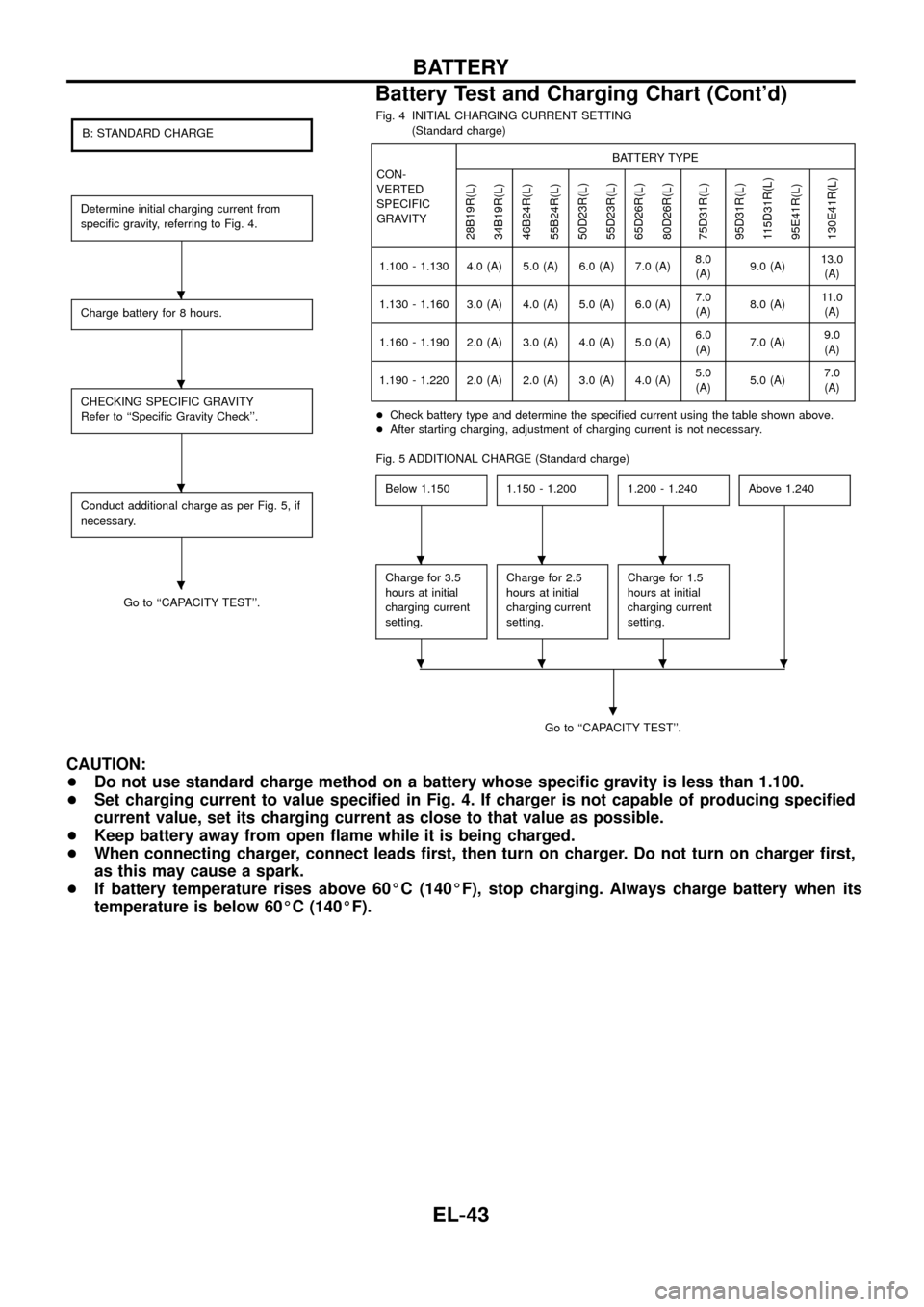
B: STANDARD CHARGE
Determine initial charging current from
speci®c gravity, referring to Fig. 4.
Charge battery for 8 hours.
CHECKING SPECIFIC GRAVITY
Refer to ``Speci®c Gravity Check''.
Conduct additional charge as per Fig. 5, if
necessary.
Go to ``CAPACITY TEST''.Fig. 4 INITIAL CHARGING CURRENT SETTING
(Standard charge)
CON-
VERTED
SPECIFIC
GRAVITYBATTERY TYPE
28B19R(L)
34B19R(L)
46B24R(L)
55B24R(L)
50D23R(L)
55D23R(L)
65D26R(L)
80D26R(L)
75D31R(L)
95D31R(L)
115D31R(L)
95E41R(L)
130E41R(L)
1.100 - 1.130 4.0 (A) 5.0 (A) 6.0 (A) 7.0 (A)8.0
(A)9.0 (A)13.0
(A)
1.130 - 1.160 3.0 (A) 4.0 (A) 5.0 (A) 6.0 (A)7.0
(A)8.0 (A)11.0
(A)
1.160 - 1.190 2.0 (A) 3.0 (A) 4.0 (A) 5.0 (A)6.0
(A)7.0 (A)9.0
(A)
1.190 - 1.220 2.0 (A) 2.0 (A) 3.0 (A) 4.0 (A)5.0
(A)5.0 (A)7.0
(A)
+Check battery type and determine the speci®ed current using the table shown above.
+After starting charging, adjustment of charging current is not necessary.
Fig. 5 ADDITIONAL CHARGE (Standard charge)
Below 1.150
1.150 - 1.2001.200 - 1.240Above 1.240
Charge for 3.5
hours at initial
charging current
setting.Charge for 2.5
hours at initial
charging current
setting.Charge for 1.5
hours at initial
charging current
setting.
Go to ``CAPACITY TEST''.
.
CAUTION:
+Do not use standard charge method on a battery whose speci®c gravity is less than 1.100.
+Set charging current to value speci®ed in Fig. 4. If charger is not capable of producing speci®ed
current value, set its charging current as close to that value as possible.
+Keep battery away from open ¯ame while it is being charged.
+When connecting charger, connect leads ®rst, then turn on charger. Do not turn on charger ®rst,
as this may cause a spark.
+If battery temperature rises above 60ÉC (140ÉF), stop charging. Always charge battery when its
temperature is below 60ÉC (140ÉF).
.
.
.
.
...
....
BATTERY
Battery Test and Charging Chart (Cont'd)
EL-43
Page 48 of 326

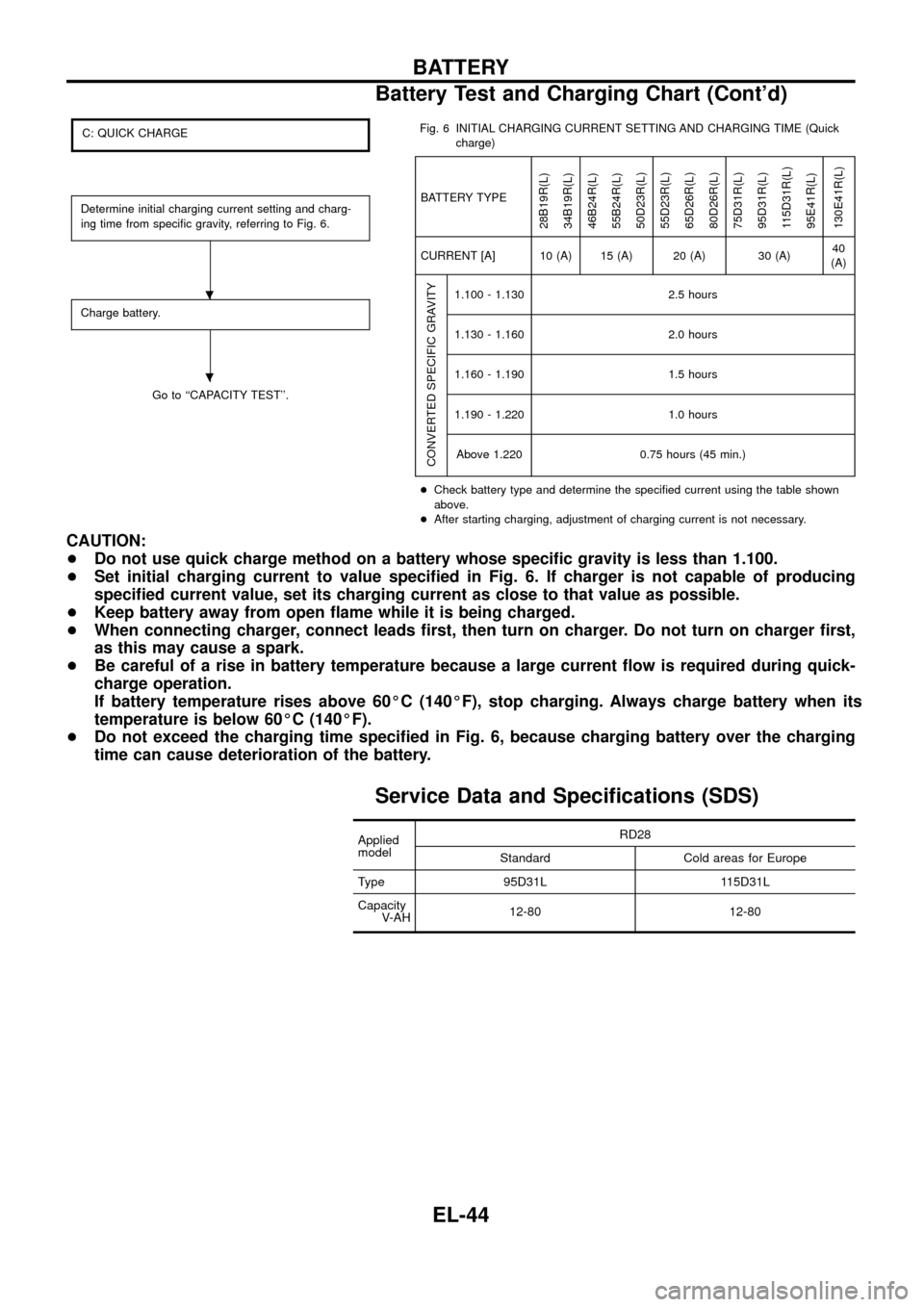
C: QUICK CHARGE
Determine initial charging current setting and charg-
ing time from speci®c gravity, referring to Fig. 6.
Charge battery.
Go to ``CAPACITY TEST''.Fig. 6 INITIAL CHARGING CURRENT SETTING AND CHARGING TIME (Quick
charge)
BATTERY TYPE
28B19R(L)
34B19R(L)
46B24R(L)
55B24R(L)
50D23R(L)
55D23R(L)
65D26R(L)
80D26R(L)
75D31R(L)
95D31R(L)
115D31R(L)
95E41R(L)
130E41R(L)
CURRENT [A] 10 (A) 15 (A) 20 (A) 30 (A)40
(A)
CONVERTED SPECIFIC GRAVITY
1.100 - 1.130 2.5 hours
1.130 - 1.160 2.0 hours
1.160 - 1.190 1.5 hours
1.190 - 1.220 1.0 hours
Above 1.220 0.75 hours (45 min.)
+Check battery type and determine the speci®ed current using the table shown
above.
+After starting charging, adjustment of charging current is not necessary.
CAUTION:
+Do not use quick charge method on a battery whose speci®c gravity is less than 1.100.
+Set initial charging current to value speci®ed in Fig. 6. If charger is not capable of producing
speci®ed current value, set its charging current as close to that value as possible.
+Keep battery away from open ¯ame while it is being charged.
+When connecting charger, connect leads ®rst, then turn on charger. Do not turn on charger ®rst,
as this may cause a spark.
+Be careful of a rise in battery temperature because a large current ¯ow is required during quick-
charge operation.
If battery temperature rises above 60ÉC (140ÉF), stop charging. Always charge battery when its
temperature is below 60ÉC (140ÉF).
+Do not exceed the charging time speci®ed in Fig. 6, because charging battery over the charging
time can cause deterioration of the battery.
Service Data and Speci®cations (SDS)
Applied
modelRD28
Standard Cold areas for Europe
Type 95D31L 115D31L
Capacity
V-AH12-80 12-80
.
.
BATTERY
Battery Test and Charging Chart (Cont'd)
EL-44
Page 54 of 326
5. Check depth of insulating mold from commutator surface.
+Less than 0.2 mm (0.008 in) ... Undercut to 0.5 to 0.8 mm
(0.020 to 0.031 in)
Assembly
Apply high-temperature grease to lubricate the bearing, gears and
frictional surface when assembling the starter.
Carefully observe the following instructions.
PINION PROTRUSION LENGTH ADJUSTMENT
Clearance ``!''
With pinion driven out by magnetic switch, push pinion back to
remove slack and measure clearance ``!'' between the front edge
of the pinion and the pinion stopper.
Clearance ``!'':
Refer to SDS (EL-51).
Movement ``!''
Compare movement ``!'' in height of pinion when it is pushed out
with magnetic switch energized and when it is pulled out by hand
until it touches stopper.
Movement ``!'':
Refer to SDS (EL-51).
SEL022Z
SEL026Z
SEL497D
STARTING SYSTEM
Inspection (Cont'd)
EL-50
Page 106 of 326
System Description
UNIFIED CONTROL METER
+Speedometer, odo/trip meter, tachometer, fuel gauge and water temperature gauge are controlled totally
by control unit combined with speedometer.
+Digital meter is adopted for odo/trip meter.*
*The record of the odo meter is kept even if the battery cable is disconnected. The record of the trip meter
is erased when the battery cable is disconnected.
+Odo/trip meter segment can be checked in diagnosis mode.
+Meter/gauge can be checked in diagnosis mode.
Note: Sub fuel gauge is not controlled by the control unit.
HOW TO CHANGE THE DISPLAY FOR ODO/TRIP METER
Note: Turn ignition switch to the ``ON'' position to operate odo/trip meter.
SEL253V
METER AND GAUGES
EL-102
Page 113 of 326
Flexible Print Circuit (FPC)
Tachometer, fuel gauge and water temperature gauge are con-
nected with uni®ed meter control unit (speedometer) by Flexible
Print Circuit (FPC) connector. When replace or remove and install
uni®ed control unit (speedometer), disconnect and connect FPC
connector according to the following steps.
DISCONNECT
1. Open connector cover.
2. Release connector lock by holding both ends of it and pulling it
up.
3. Disconnect FPC by pulling it up.
CONNECT
1. Insert FPC into connector and lock connector pushing FPC
downward.
2. Check secure connection of FPC.
3. Check continuity of check land terminal for secure connection
of FPC.
Resistance: 0W
4. Close connector cover.
SEL109V
SEL114V
METER AND GAUGES
EL-109