Page 4 of 326

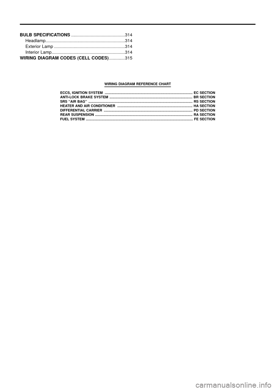
BULB SPECIFICATIONS............................................314
Headlamp.................................................................314
Exterior Lamp ..........................................................314
Interior Lamp............................................................314
WIRING DIAGRAM CODES (CELL CODES) .............315
WIRING DIAGRAM REFERENCE CHART
ECCS, IGNITION SYSTEM ........................................................................\
................... EC SECTION
ANTI-LOCK BRAKE SYSTEM ........................................................................\
.............. BR SECTION
SRS ``AIR BAG'' ........................................................................\
.................................... RS SECT ION
HEATER AND AIR CONDITIONER ........................................................................\
...... HA SECTION
DIFFERENTIAL CARRIER ........................................................................\
.................... PD SECTION
REAR SUSPENSION ........................................................................\
............................. RA SECTION
FUEL SYSTEM ........................................................................\
....................................... FE SECT ION
Page 10 of 326
Wiring Diagram Ð POWER Ð
BATTERY POWER SUPPLY Ð IGNITION SW. IN ANY POSITION
TEL479A
POWER SUPPLY ROUTING
EL-6
Page 14 of 326
ACCESSORY POWER SUPPLY Ð IGNITION SW. IN ``ACC'' OR ``ON''
TEL483A
POWER SUPPLY ROUTING
Wiring Diagram Ð POWER Ð (Cont'd)
EL-10
Page 15 of 326
IGNITION POWER SUPPLY Ð IGNITION SW. IN ``ON'' AND/OR ``START''
TEL484A
POWER SUPPLY ROUTING
Wiring Diagram Ð POWER Ð (Cont'd)
EL-11
Page 50 of 326

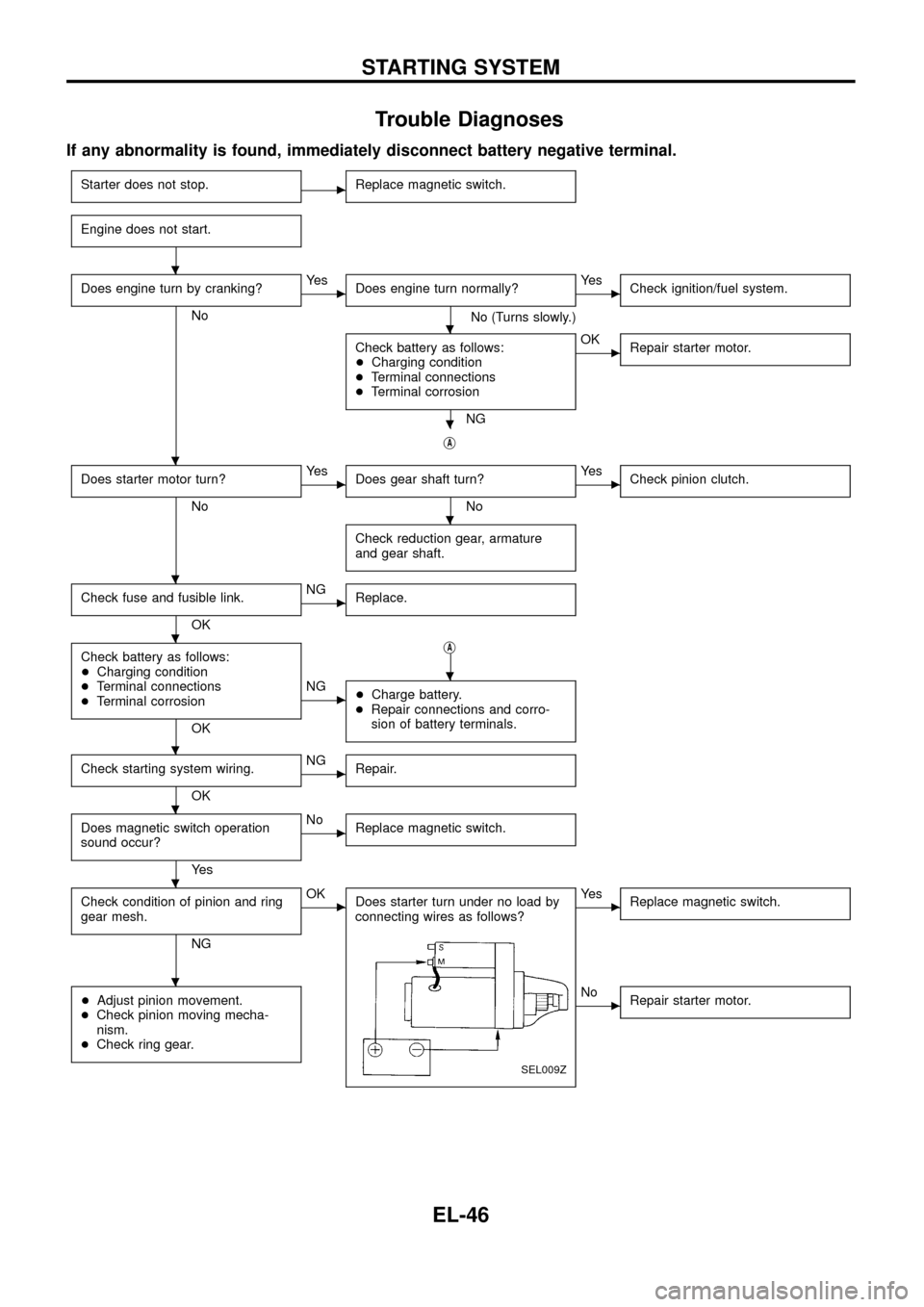
Trouble Diagnoses
If any abnormality is found, immediately disconnect battery negative terminal.
Starter does not stop.cReplace magnetic switch.
Engine does not start.
Does engine turn by cranking?
No
cYe s
Does engine turn normally?
No (Turns slowly.)
cYe s
Check ignition/fuel system.
Check battery as follows:
+Charging condition
+Terminal connections
+Terminal corrosion
NG
cOK
Repair starter motor.
jA
Does starter motor turn?
No
cYe s
Does gear shaft turn?
No
cYe s
Check pinion clutch.
Check reduction gear, armature
and gear shaft.
Check fuse and fusible link.
OK
cNG
Replace.
Check battery as follows:
+Charging condition
+Terminal connections
+Terminal corrosion
OKj
A
cNG
+Charge battery.
+Repair connections and corro-
sion of battery terminals.
Check starting system wiring.
OK
cNG
Repair.
Does magnetic switch operation
sound occur?
Ye s
cNo
Replace magnetic switch.
Check condition of pinion and ring
gear mesh.
NG
cOK
Does starter turn under no load by
connecting wires as follows?
SEL009Z
cYe s
Replace magnetic switch.
+Adjust pinion movement.
+Check pinion moving mecha-
nism.
+Check ring gear.cNo
Repair starter motor.
.
.
.
.
.
.
.
.
.
.
.
.
STARTING SYSTEM
EL-46
Page 89 of 326

Trouble Diagnoses
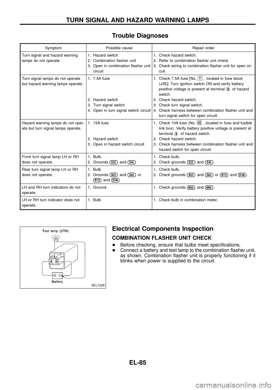
Symptom Possible cause Repair order
Turn signal and hazard warning
lamps do not operate.1. Hazard switch
2. Combination ¯asher unit
3. Open in combination ¯asher unit
circuit1. Check hazard switch.
2. Refer to combination ¯asher unit check.
3. Check wiring to combination ¯asher unit for open cir-
cuit.
Turn signal lamps do not operate
but hazard warning lamps operate.1. 7.5A fuse
2. Hazard switch
3. Turn signal switch
4. Open in turn signal switch circuit1. Check 7.5A fuse [No.
11, located in fuse block
(J/B)]. Turn ignition switch ON and verify battery
positive voltage is present at terminalj
2of hazard
switch.
2. Check hazard switch.
3. Check turn signal switch.
4. Check harness between combination ¯asher unit and
turn signal switch for open circuit.
Hazard warning lamps do not oper-
ate but turn signal lamps operate.1. 15A fuse
2. Hazard switch
3. Open in hazard switch circuit1. Check 10A fuse (No.
48, located in fuse and fusible
link box). Verify battery positive voltage is present at
terminalj
3of hazard switch.
2. Check hazard switch.
3. Check harness between combination ¯asher unit and
hazard switch for open circuit.
Front turn signal lamp LH or RH
does not operate.1. Bulb
2. Grounds
E25andE40
1. Check bulb.
2. Check grounds
E25andE40.
Rear turn signal lamp LH or RH
does not operate.1. Bulb
2. Grounds
B23andD83or
B112andD106
1. Check bulb.
2. Check grounds
B23andD83orB112andD106.
LH and RH turn indicators do not
operate.1. Ground 1. Check grounds
M30andM98.
LH or RH turn indicator does not
operate.1. Bulb 1. Check bulb in combination meter.
Electrical Components Inspection
COMBINATION FLASHER UNIT CHECK
+Before checking, ensure that bulbs meet speci®cations.
+Connect a battery and test lamp to the combination ¯asher unit,
as shown. Combination ¯asher unit is properly functioning if it
blinks when power is supplied to the circuit.
SEL122E
TURN SIGNAL AND HAZARD WARNING LAMPS
EL-85
Page 176 of 326

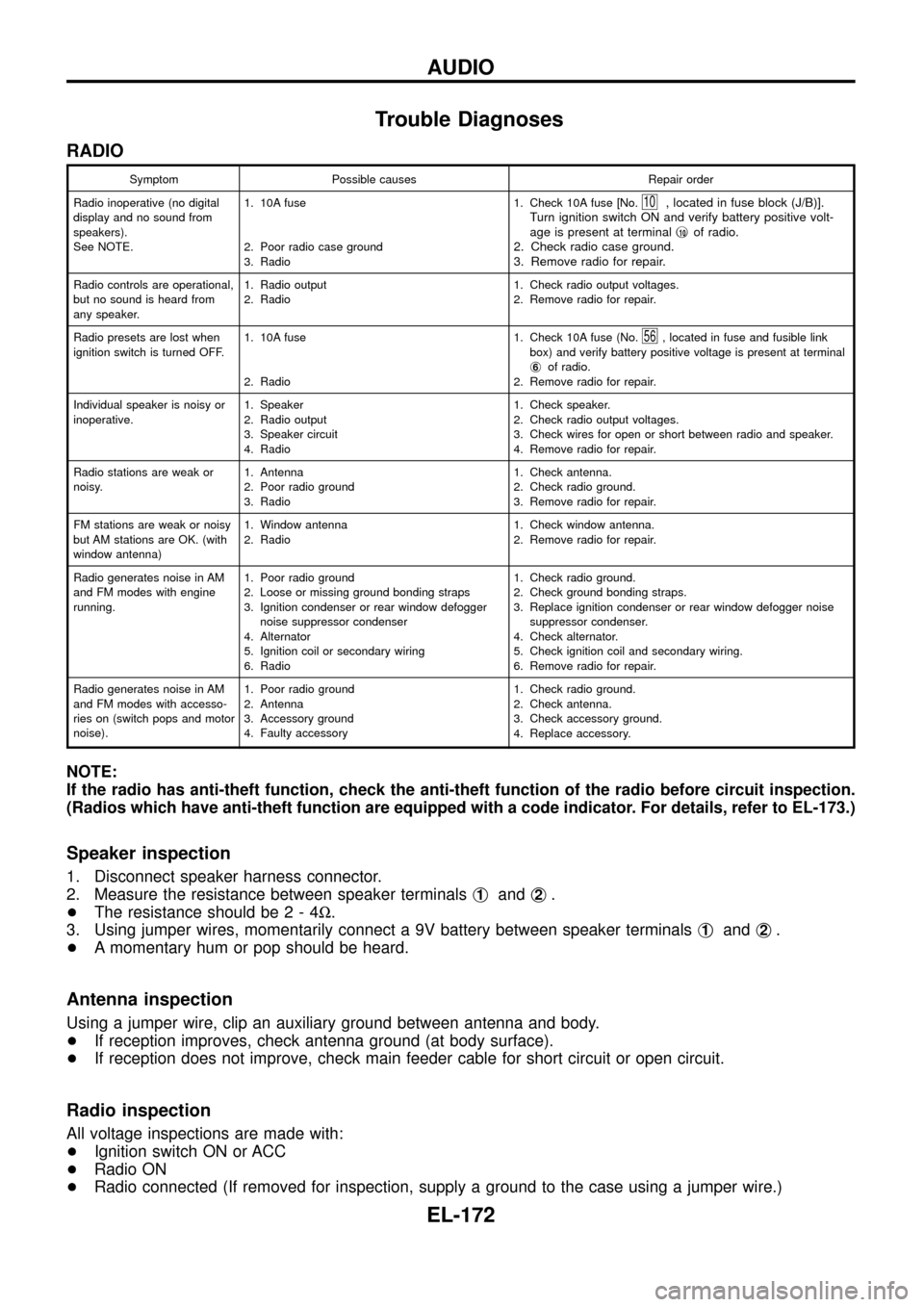
Trouble Diagnoses
RADIO
Symptom Possible causes Repair order
Radio inoperative (no digital
display and no sound from
speakers).
See NOTE.1. 10A fuse
2. Poor radio case ground
3. Radio1. Check 10A fuse [No.
10, located in fuse block (J/B)].
Turn ignition switch ON and verify battery positive volt-
age is present at terminalj
10of radio.
2. Check radio case ground.
3. Remove radio for repair.
Radio controls are operational,
but no sound is heard from
any speaker.1. Radio output
2. Radio1. Check radio output voltages.
2. Remove radio for repair.
Radio presets are lost when
ignition switch is turned OFF.1. 10A fuse
2. Radio1. Check 10A fuse (No.
56, located in fuse and fusible link
box) and verify battery positive voltage is present at terminal
j
6of radio.
2. Remove radio for repair.
Individual speaker is noisy or
inoperative.1. Speaker
2. Radio output
3. Speaker circuit
4. Radio1. Check speaker.
2. Check radio output voltages.
3. Check wires for open or short between radio and speaker.
4. Remove radio for repair.
Radio stations are weak or
noisy.1. Antenna
2. Poor radio ground
3. Radio1. Check antenna.
2. Check radio ground.
3. Remove radio for repair.
FM stations are weak or noisy
but AM stations are OK. (with
window antenna)1. Window antenna
2. Radio1. Check window antenna.
2. Remove radio for repair.
Radio generates noise in AM
and FM modes with engine
running.1. Poor radio ground
2. Loose or missing ground bonding straps
3. Ignition condenser or rear window defogger
noise suppressor condenser
4. Alternator
5. Ignition coil or secondary wiring
6. Radio1. Check radio ground.
2. Check ground bonding straps.
3. Replace ignition condenser or rear window defogger noise
suppressor condenser.
4. Check alternator.
5. Check ignition coil and secondary wiring.
6. Remove radio for repair.
Radio generates noise in AM
and FM modes with accesso-
ries on (switch pops and motor
noise).1. Poor radio ground
2. Antenna
3. Accessory ground
4. Faulty accessory1. Check radio ground.
2. Check antenna.
3. Check accessory ground.
4. Replace accessory.
NOTE:
If the radio has anti-theft function, check the anti-theft function of the radio before circuit inspection.
(Radios which have anti-theft function are equipped with a code indicator. For details, refer to EL-173.)
Speaker inspection
1. Disconnect speaker harness connector.
2. Measure the resistance between speaker terminalsj
1andj2.
+The resistance should be2-4W.
3. Using jumper wires, momentarily connect a 9V battery between speaker terminalsj
1andj2.
+A momentary hum or pop should be heard.
Antenna inspection
Using a jumper wire, clip an auxiliary ground between antenna and body.
+If reception improves, check antenna ground (at body surface).
+If reception does not improve, check main feeder cable for short circuit or open circuit.
Radio inspection
All voltage inspections are made with:
+Ignition switch ON or ACC
+Radio ON
+Radio connected (If removed for inspection, supply a ground to the case using a jumper wire.)
AUDIO
EL-172
Page 235 of 326
DIAGNOSTIC PROCEDURE 6
(NATS release signal check)
Does engine start properly?
Ye s
cNo
Check NATS system.
CHECK NATS SIGNAL CIRCUIT.
1. Disconnect control unit connector and
NATS IMMU connector.
2. Check continuity between control unit
terminalj
9and NATS IMMU terminal
j
3(LHD models),j7(RHD models).
Continuity should exist.
3. Check continuity between control unit
terminalj
9and ground.
Continuity should not exist.
Refer to wiring diagram in EL-215
(LHD), EL-219 (RHD).
OK
cNG
Repair harness.
CHECK NATS RELEASE SIGNAL.
1. Connect control unit connector and
NATS IMMU connector.
2. Check voltage between control unit ter-
minalj
9and ground.
OK
cNG
Check NATS system.
Replace super lock control unit.
Ignition switch conditionVoltage
[V]
OFF
5
More than 10 seconds after ignition
switch turned ON
For 10 seconds after ignition switch
turned ONPulse
SEL493V
SEL494V
SEL495V
.
.
.
POWER DOOR LOCK Ð Super Lock Ð
Trouble Diagnoses (Cont'd)
EL-231