SYMPTOM CHART
Symptom chart 1 (Malfunction is indicated in Diagnosis mode)
Symptom Possible causes Repair order
Speedometer and/or odo/trip
meter indicate(s) malfunction
in Diagnosis mode.+Speedometer (Uni®ed meter control unit)+Replace speedometer (uni®ed meter control unit).
Multiple meter/gauge indicate
malfunction in Diagnosis
mode.
One of tachometer/fuel gauge/
water temp. gauge indicates
malfunction in Diagnosis
mode.+Meter/Gauge
+Speedometer (Uni®ed meter control unit)1. Check resistance of meter/gauge indicating malfunction. If
the resistance is NG, replace the meter/gauge. Refer to
``METER/GAUGE RESISTANCE CHECK'', EL-114.
2. If the resistance is OK, replace speedometer (uni®ed meter
control unit).
Symptom chart 2 (No malfunction is indicated in Diagnosis mode)
Symptom Possible causes Repair order
Speedometer and odo/trip
meter are malfunctioning.1. Sensor
- Speedometer, Odo/Trip meter
2. FPC connector
3. Speedometer (Uni®ed meter control unit)1. Check vehicle speed sensor.
INSPECTION/VEHICLE SPEED SENSOR (Refer to EL-112.)
2. Check FPC connector. Refer to ``Flexible Print Circuit
(FPC)'', EL-109.
3. Replace speedometer (uni®ed meter control unit).
Multiple meter/gauge are mal-
functioning. (except
speedometer, odo/trip meter)1. FPC connector
2. Speedometer (Uni®ed meter control unit)1. Check FPC connector. Refer to ``Flexible Print Circuit
(FPC)'', EL-109.
2. Replace speedometer (uni®ed meter control unit).
One of tachometer/fuel gauge/
water temp. gauge is malfunc-
tioning.1. Sensor/Engine revolution signal
- Tachometer
- Fuel gauge
- Water temp. gauge
2. FPC connector
3. Speedometer (Uni®ed meter control unit)1. Check the sensor for malfunctioning meter/gauge.
INSPECTION/ENGINE REVOLUTION SIGNAL (Refer to
EL-113.)
INSPECTION/FUEL TANK GAUGE (Refer to EL-113.)
INSPECTION/THERMAL TRANSMITTER (Refer to EL-114.)
2. Check FPC connector. Refer to ``Flexible Print Circuit
(FPC)'', EL-109.
3. Replace speedometer (uni®ed meter control unit).
Before starting trouble diagnoses above, perform PRELIMINARY CHECK, EL-110.
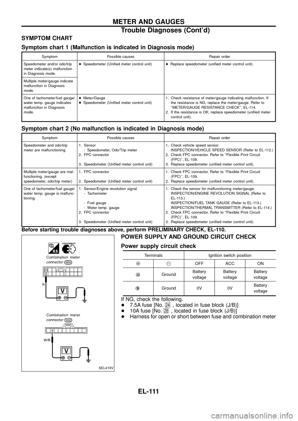
POWER SUPPLY AND GROUND CIRCUIT CHECK
Power supply circuit check
Terminals Ignition switch position
Å@OFF ACC ON
j
33GroundBattery
voltageBattery
voltageBattery
voltage
j
9Ground 0V 0VBattery
voltage
If NG, check the following.
+7.5A fuse [No.
24, located in fuse block (J/B)]
+10A fuse [No.
28, located in fuse block (J/B)]
+Harness for open or short between fuse and combination meter
SEL419V
METER AND GAUGES
Trouble Diagnoses (Cont'd)
EL-111