1998 NISSAN PATROL Charging system
[x] Cancel search: Charging systemPage 1 of 326
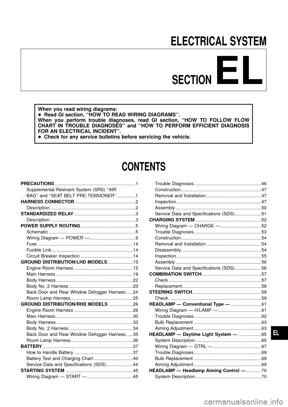
ELECTRICAL SYSTEM
SECTION
EL
When you read wiring diagrams:
+Read GI section, ``HOW TO READ WIRING DIAGRAMS''.
When you perform trouble diagnoses, read GI section, ``HOW TO FOLLOW FLOW
CHART IN TROUBLE DIAGNOSES'' and ``HOW TO PERFORM EFFICIENT DIAGNOSIS
FOR AN ELECTRICAL INCIDENT''.
+Check for any service bulletins before servicing the vehicle.
CONTENTS
PRECAUTIONS...............................................................1
Supplemental Restraint System (SRS) ``AIR
BAG'' and ``SEAT BELT PRE-TENSIONER''...............1
HARNESS CONNECTOR................................................2
Description ...................................................................2
STANDARDIZED RELAY................................................3
Description ...................................................................3
POWER SUPPLY ROUTING...........................................5
Schematic ....................................................................5
Wiring Diagram Ð POWER Ð....................................6
Fuse ...........................................................................14
Fusible Link................................................................14
Circuit Breaker Inspection .........................................14
GROUND DISTRIBUTION/LHD MODELS....................15
Engine Room Harness ..............................................15
Main Harness.............................................................19
Body Harness ............................................................22
Body No. 2 Harness ..................................................23
Back Door and Rear Window Defogger Harness .....24
Room Lamp Harness.................................................25
GROUND DISTRIBUTION/RHD MODELS...................26
Engine Room Harness ..............................................26
Main Harness.............................................................30
Body Harness ............................................................33
Body No. 2 Harness ..................................................34
Back Door and Rear Window Defogger Harness .....35
Room Lamp Harness.................................................36
BATTERY.......................................................................37
How to Handle Battery ..............................................37
Battery Test and Charging Chart ...............................40
Service Data and Speci®cations (SDS).....................44
STARTING SYSTEM.....................................................45
Wiring Diagram Ð START Ð ....................................45Trouble Diagnoses.....................................................46
Construction ...............................................................47
Removal and Installation ...........................................47
Inspection...................................................................47
Assembly ...................................................................50
Service Data and Speci®cations (SDS).....................51
CHARGING SYSTEM....................................................52
Wiring Diagram Ð CHARGE Ð ................................52
Trouble Diagnoses.....................................................53
Construction ...............................................................54
Removal and Installation ...........................................54
Disassembly...............................................................54
Inspection...................................................................55
Assembly ...................................................................56
Service Data and Speci®cations (SDS).....................56
COMBINATION SWITCH...............................................57
Check .........................................................................57
Replacement ..............................................................58
STEERING SWITCH......................................................59
Check .........................................................................59
HEADLAMP Ð Conventional Type Ð........................61
Wiring Diagram Ð H/LAMP Ð ..................................61
Trouble Diagnoses.....................................................62
Bulb Replacement .....................................................63
Aiming Adjustment .....................................................63
HEADLAMP Ð Daytime Light System Ð..................65
System Description ....................................................65
Wiring Diagram Ð DTRL Ð ......................................67
Trouble Diagnoses.....................................................69
Bulb Replacement .....................................................69
Aiming Adjustment .....................................................69
HEADLAMP Ð Headlamp Aiming Control Ð............70
System Description ....................................................70
EL
Page 50 of 326
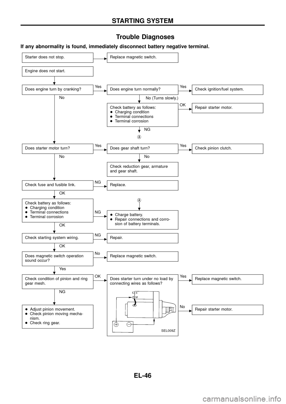
Trouble Diagnoses
If any abnormality is found, immediately disconnect battery negative terminal.
Starter does not stop.cReplace magnetic switch.
Engine does not start.
Does engine turn by cranking?
No
cYe s
Does engine turn normally?
No (Turns slowly.)
cYe s
Check ignition/fuel system.
Check battery as follows:
+Charging condition
+Terminal connections
+Terminal corrosion
NG
cOK
Repair starter motor.
jA
Does starter motor turn?
No
cYe s
Does gear shaft turn?
No
cYe s
Check pinion clutch.
Check reduction gear, armature
and gear shaft.
Check fuse and fusible link.
OK
cNG
Replace.
Check battery as follows:
+Charging condition
+Terminal connections
+Terminal corrosion
OKj
A
cNG
+Charge battery.
+Repair connections and corro-
sion of battery terminals.
Check starting system wiring.
OK
cNG
Repair.
Does magnetic switch operation
sound occur?
Ye s
cNo
Replace magnetic switch.
Check condition of pinion and ring
gear mesh.
NG
cOK
Does starter turn under no load by
connecting wires as follows?
SEL009Z
cYe s
Replace magnetic switch.
+Adjust pinion movement.
+Check pinion moving mecha-
nism.
+Check ring gear.cNo
Repair starter motor.
.
.
.
.
.
.
.
.
.
.
.
.
STARTING SYSTEM
EL-46
Page 56 of 326
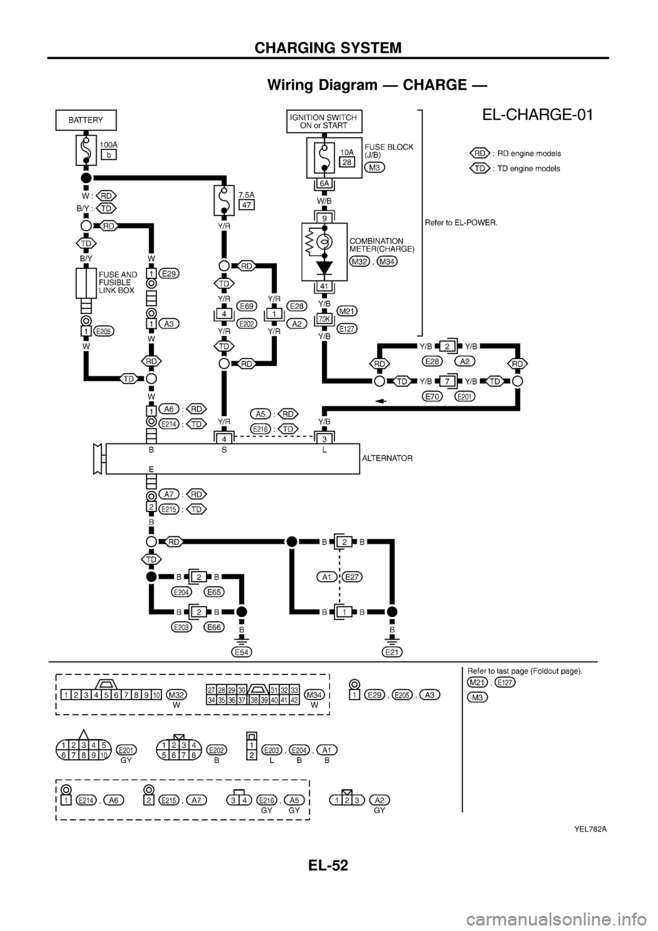
Wiring Diagram Ð CHARGE Ð
YEL782A
CHARGING SYSTEM
EL-52
Page 57 of 326
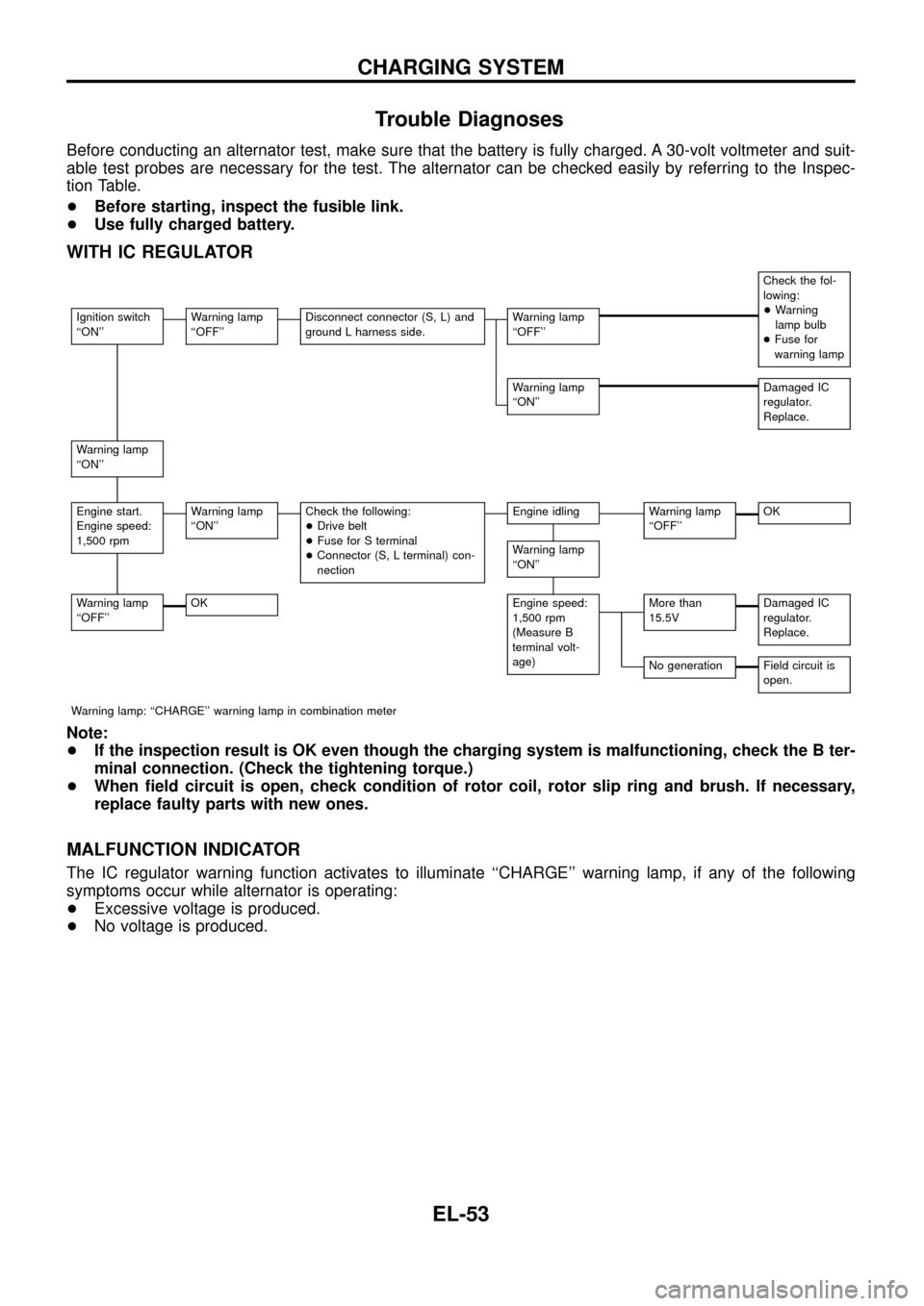
Trouble Diagnoses
Before conducting an alternator test, make sure that the battery is fully charged. A 30-volt voltmeter and suit-
able test probes are necessary for the test. The alternator can be checked easily by referring to the Inspec-
tion Table.
+Before starting, inspect the fusible link.
+Use fully charged battery.
WITH IC REGULATOR
Check the fol-
lowing:
+Warning
lamp bulb
+Fuse for
warning lamp
Ignition switch
``ON''Warning lamp
``OFF''Disconnect connector (S, L) and
ground L harness side.Warning lamp
``OFF''
Warning lamp
``ON''Damaged IC
regulator.
Replace.
Warning lamp
``ON''
Engine start.
Engine speed:
1,500 rpmWarning lamp
``ON''Check the following:
+Drive belt
+Fuse for S terminal
+Connector (S, L terminal) con-
nectionEngine idlingWarning lamp
``OFF''OK
Warning lamp
``ON''
Warning lamp
``OFF''OKEngine speed:
1,500 rpm
(Measure B
terminal volt-
age)More than
15.5VDamaged IC
regulator.
Replace.
No generationField circuit is
open.
Warning lamp: ``CHARGE'' warning lamp in combination meter
Note:
+If the inspection result is OK even though the charging system is malfunctioning, check the B ter-
minal connection. (Check the tightening torque.)
+When ®eld circuit is open, check condition of rotor coil, rotor slip ring and brush. If necessary,
replace faulty parts with new ones.
MALFUNCTION INDICATOR
The IC regulator warning function activates to illuminate ``CHARGE'' warning lamp, if any of the following
symptoms occur while alternator is operating:
+Excessive voltage is produced.
+No voltage is produced.
CHARGING SYSTEM
EL-53
Page 58 of 326
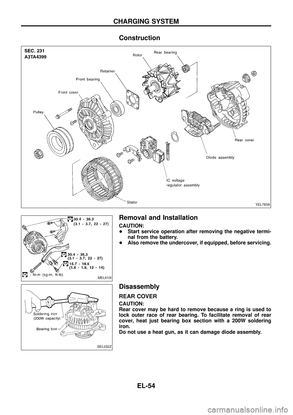
Construction
Removal and Installation
CAUTION:
+Start service operation after removing the negative termi-
nal from the battery.
+Also remove the undercover, if equipped, before servicing.
Disassembly
REAR COVER
CAUTION:
Rear cover may be hard to remove because a ring is used to
lock outer race of rear bearing. To facilitate removal of rear
cover, heat just bearing box section with a 200W soldering
iron.
Do not use a heat gun, as it can damage diode assembly.
YEL783A
MEL610I
SEL032Z
CHARGING SYSTEM
EL-54
Page 59 of 326
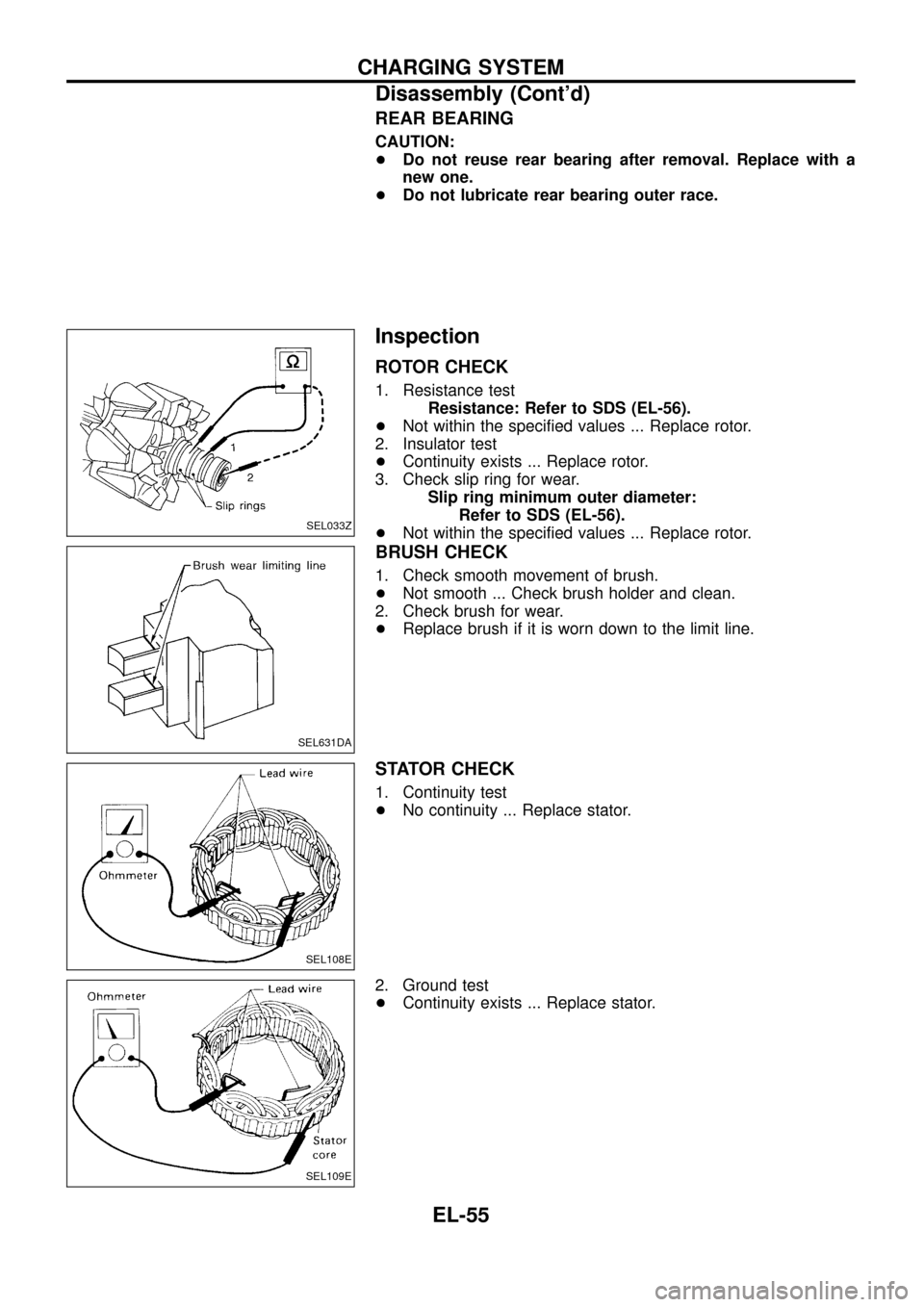
REAR BEARING
CAUTION:
+Do not reuse rear bearing after removal. Replace with a
new one.
+Do not lubricate rear bearing outer race.
Inspection
ROTOR CHECK
1. Resistance test
Resistance: Refer to SDS (EL-56).
+Not within the speci®ed values ... Replace rotor.
2. Insulator test
+Continuity exists ... Replace rotor.
3. Check slip ring for wear.
Slip ring minimum outer diameter:
Refer to SDS (EL-56).
+Not within the speci®ed values ... Replace rotor.
BRUSH CHECK
1. Check smooth movement of brush.
+Not smooth ... Check brush holder and clean.
2. Check brush for wear.
+Replace brush if it is worn down to the limit line.
STATOR CHECK
1. Continuity test
+No continuity ... Replace stator.
2. Ground test
+Continuity exists ... Replace stator.
SEL033Z
SEL631DA
SEL108E
SEL109E
CHARGING SYSTEM
Disassembly (Cont'd)
EL-55
Page 60 of 326
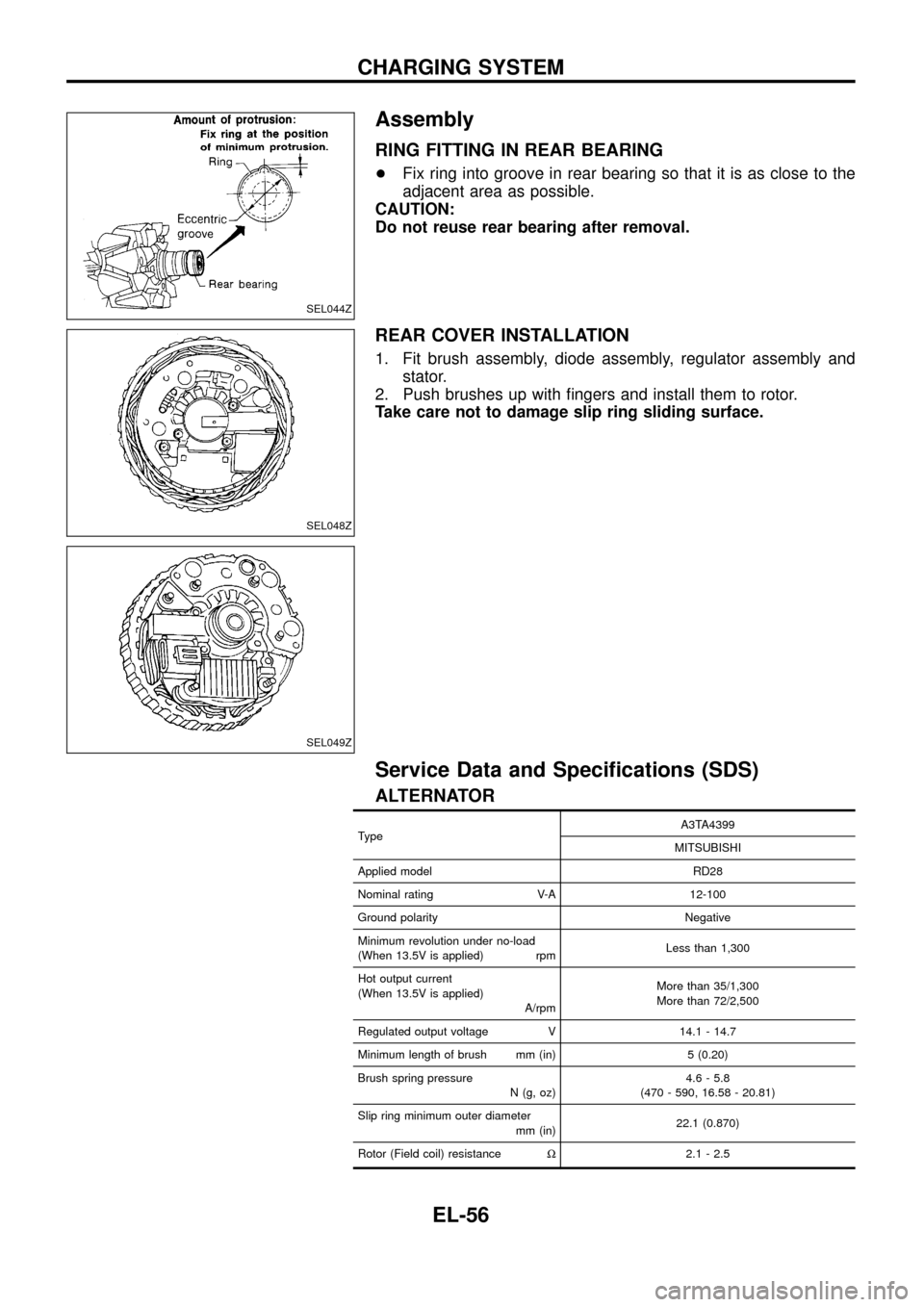
Assembly
RING FITTING IN REAR BEARING
+Fix ring into groove in rear bearing so that it is as close to the
adjacent area as possible.
CAUTION:
Do not reuse rear bearing after removal.
REAR COVER INSTALLATION
1. Fit brush assembly, diode assembly, regulator assembly and
stator.
2. Push brushes up with ®ngers and install them to rotor.
Take care not to damage slip ring sliding surface.
Service Data and Speci®cations (SDS)
ALTERNATOR
TypeA3TA4399
MITSUBISHI
Applied model RD28
Nominal rating V-A 12-100
Ground polarity Negative
Minimum revolution under no-load
(When 13.5V is applied) rpmLess than 1,300
Hot output current
(When 13.5V is applied)
A/rpmMore than 35/1,300
More than 72/2,500
Regulated output voltage V 14.1 - 14.7
Minimum length of brush mm (in) 5 (0.20)
Brush spring pressure
N (g, oz)4.6 - 5.8
(470 - 590, 16.58 - 20.81)
Slip ring minimum outer diameter
mm (in)22.1 (0.870)
Rotor (Field coil) resistanceW2.1 - 2.5
SEL044Z
SEL048Z
SEL049Z
CHARGING SYSTEM
EL-56
Page 319 of 326
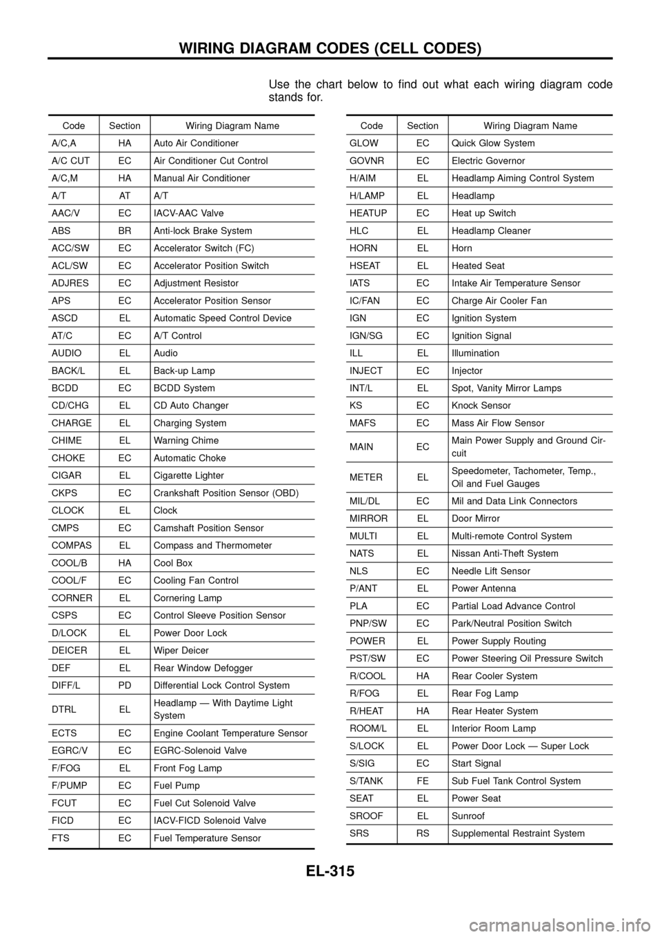
Use the chart below to ®nd out what each wiring diagram code
stands for.
Code Section Wiring Diagram Name
A/C,A HA Auto Air Conditioner
A/C CUT EC Air Conditioner Cut Control
A/C,M HA Manual Air Conditioner
A/T AT A/T
AAC/V EC IACV-AAC Valve
ABS BR Anti-lock Brake System
ACC/SW EC Accelerator Switch (FC)
ACL/SW EC Accelerator Position Switch
ADJRES EC Adjustment Resistor
APS EC Accelerator Position Sensor
ASCD EL Automatic Speed Control Device
AT/C EC A/T Control
AUDIO EL Audio
BACK/L EL Back-up Lamp
BCDD EC BCDD System
CD/CHG EL CD Auto Changer
CHARGE EL Charging System
CHIME EL Warning Chime
CHOKE EC Automatic Choke
CIGAR EL Cigarette Lighter
CKPS EC Crankshaft Position Sensor (OBD)
CLOCK EL Clock
CMPS EC Camshaft Position Sensor
COMPAS EL Compass and Thermometer
COOL/B HA Cool Box
COOL/F EC Cooling Fan Control
CORNER EL Cornering Lamp
CSPS EC Control Sleeve Position Sensor
D/LOCK EL Power Door Lock
DEICER EL Wiper Deicer
DEF EL Rear Window Defogger
DIFF/L PD Differential Lock Control System
DTRL ELHeadlamp Ð With Daytime Light
System
ECTS EC Engine Coolant Temperature Sensor
EGRC/V EC EGRC-Solenoid Valve
F/FOG EL Front Fog Lamp
F/PUMP EC Fuel Pump
FCUT EC Fuel Cut Solenoid Valve
FICD EC IACV-FICD Solenoid Valve
FTS EC Fuel Temperature SensorCode Section Wiring Diagram Name
GLOW EC Quick Glow System
GOVNR EC Electric Governor
H/AIM EL Headlamp Aiming Control System
H/LAMP EL Headlamp
HEATUP EC Heat up Switch
HLC EL Headlamp Cleaner
HORN EL Horn
HSEAT EL Heated Seat
IATS EC Intake Air Temperature Sensor
IC/FAN EC Charge Air Cooler Fan
IGN EC Ignition System
IGN/SG EC Ignition Signal
ILL EL Illumination
INJECT EC Injector
INT/L EL Spot, Vanity Mirror Lamps
KS EC Knock Sensor
MAFS EC Mass Air Flow Sensor
MAIN ECMain Power Supply and Ground Cir-
cuit
METER ELSpeedometer, Tachometer, Temp.,
Oil and Fuel Gauges
MIL/DL EC Mil and Data Link Connectors
MIRROR EL Door Mirror
MULTI EL Multi-remote Control System
NATS EL Nissan Anti-Theft System
NLS EC Needle Lift Sensor
P/ANT EL Power Antenna
PLA EC Partial Load Advance Control
PNP/SW EC Park/Neutral Position Switch
POWER EL Power Supply Routing
PST/SW EC Power Steering Oil Pressure Switch
R/COOL HA Rear Cooler System
R/FOG EL Rear Fog Lamp
R/HEAT HA Rear Heater System
ROOM/L EL Interior Room Lamp
S/LOCK EL Power Door Lock Ð Super Lock
S/SIG EC Start Signal
S/TANK FE Sub Fuel Tank Control System
SEAT EL Power Seat
SROOF EL Sunroof
SRS RS Supplemental Restraint System
WIRING DIAGRAM CODES (CELL CODES)
EL-315