1998 NISSAN PATROL Back
[x] Cancel search: BackPage 1 of 326
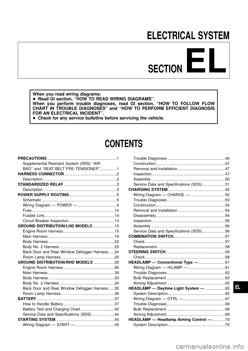
ELECTRICAL SYSTEM
SECTION
EL
When you read wiring diagrams:
+Read GI section, ``HOW TO READ WIRING DIAGRAMS''.
When you perform trouble diagnoses, read GI section, ``HOW TO FOLLOW FLOW
CHART IN TROUBLE DIAGNOSES'' and ``HOW TO PERFORM EFFICIENT DIAGNOSIS
FOR AN ELECTRICAL INCIDENT''.
+Check for any service bulletins before servicing the vehicle.
CONTENTS
PRECAUTIONS...............................................................1
Supplemental Restraint System (SRS) ``AIR
BAG'' and ``SEAT BELT PRE-TENSIONER''...............1
HARNESS CONNECTOR................................................2
Description ...................................................................2
STANDARDIZED RELAY................................................3
Description ...................................................................3
POWER SUPPLY ROUTING...........................................5
Schematic ....................................................................5
Wiring Diagram Ð POWER Ð....................................6
Fuse ...........................................................................14
Fusible Link................................................................14
Circuit Breaker Inspection .........................................14
GROUND DISTRIBUTION/LHD MODELS....................15
Engine Room Harness ..............................................15
Main Harness.............................................................19
Body Harness ............................................................22
Body No. 2 Harness ..................................................23
Back Door and Rear Window Defogger Harness .....24
Room Lamp Harness.................................................25
GROUND DISTRIBUTION/RHD MODELS...................26
Engine Room Harness ..............................................26
Main Harness.............................................................30
Body Harness ............................................................33
Body No. 2 Harness ..................................................34
Back Door and Rear Window Defogger Harness .....35
Room Lamp Harness.................................................36
BATTERY.......................................................................37
How to Handle Battery ..............................................37
Battery Test and Charging Chart ...............................40
Service Data and Speci®cations (SDS).....................44
STARTING SYSTEM.....................................................45
Wiring Diagram Ð START Ð ....................................45Trouble Diagnoses.....................................................46
Construction ...............................................................47
Removal and Installation ...........................................47
Inspection...................................................................47
Assembly ...................................................................50
Service Data and Speci®cations (SDS).....................51
CHARGING SYSTEM....................................................52
Wiring Diagram Ð CHARGE Ð ................................52
Trouble Diagnoses.....................................................53
Construction ...............................................................54
Removal and Installation ...........................................54
Disassembly...............................................................54
Inspection...................................................................55
Assembly ...................................................................56
Service Data and Speci®cations (SDS).....................56
COMBINATION SWITCH...............................................57
Check .........................................................................57
Replacement ..............................................................58
STEERING SWITCH......................................................59
Check .........................................................................59
HEADLAMP Ð Conventional Type Ð........................61
Wiring Diagram Ð H/LAMP Ð ..................................61
Trouble Diagnoses.....................................................62
Bulb Replacement .....................................................63
Aiming Adjustment .....................................................63
HEADLAMP Ð Daytime Light System Ð..................65
System Description ....................................................65
Wiring Diagram Ð DTRL Ð ......................................67
Trouble Diagnoses.....................................................69
Bulb Replacement .....................................................69
Aiming Adjustment .....................................................69
HEADLAMP Ð Headlamp Aiming Control Ð............70
System Description ....................................................70
EL
Page 2 of 326
Wiring Diagram Ð H/AIM Ð .....................................71
PARKING, LICENSE AND TAIL LAMPS......................73
Wiring Diagram Ð TAIL/L Ð/Type A .........................73
Wiring Diagram Ð TAIL/L Ð/Type B.........................75
STOP LAMP..................................................................77
Wiring Diagram Ð STOP/L Ð/Type A ......................77
BACK-UP LAMP............................................................78
Wiring Diagram Ð BACK/L Ð/LHD Models..............78
Wiring Diagram Ð BACK/L Ð/RHD Models .............79
REAR FOG LAMP.........................................................80
Wiring Diagram Ð R/FOG Ð ....................................80
TURN SIGNAL AND HAZARD WARNING LAMPS.....81
Wiring Diagram Ð TURN Ð/Type A .........................81
Wiring Diagram Ð TURN Ð/Type B .........................83
Trouble Diagnoses.....................................................85
Electrical Components Inspection .............................85
ILLUMINATION..............................................................86
Schematic ..................................................................86
Wiring Diagram Ð ILL Ð ..........................................87
INTERIOR ROOM LAMP Ð With Timer Ð.................93
System Description ....................................................93
Schematic ..................................................................94
Wiring Diagram Ð ROOM/L Ð/LHD Models ............95
Wiring Diagram Ð ROOM/L Ð/RHD Models............98
Trouble Diagnoses...................................................100
MAP AND VANITY MIRROR LAMPS.........................101
Wiring Diagram Ð INT/L Ð.....................................101
METER AND GAUGES...............................................102
System Description ..................................................102
Combination Meter ..................................................103
Wiring Diagram Ð METER Ð/LHD Models............104
Wiring Diagram Ð METER Ð/RHD Models ...........106
Meter/Gauge Operation and Odo/Trip Meter
Segment Check in Diagnosis Mode ........................108
Flexible Print Circuit (FPC) ......................................109
Trouble Diagnoses................................................... 110
Electrical Components Inspection ........................... 114
COMPASS AND THERMOMETER............................. 116
System Description .................................................. 116
Wiring Diagram Ð COMPAS Ð .............................. 117
Trouble Diagnoses................................................... 118
Calibration Procedure For Compass ....................... 119
WARNING LAMPS......................................................121
Schematic ................................................................121
Wiring Diagram Ð WARN Ð ..................................123
Electrical Components Inspection ...........................134
WARNING CHIME.......................................................135
System Description ..................................................135
Wiring Diagram Ð CHIME Ð/LHD Models.............136
Wiring Diagram Ð CHIME Ð/RHD Models ............137
Trouble Diagnoses...................................................138
Electrical Components Inspection ...........................140FRONT WIPER AND WASHER..................................141
System Description ..................................................141
Wiring Diagram Ð WIPER Ð/With Intermittent
Wiper........................................................................142
Removal and Installation .........................................143
Washer Nozzle Adjustment .....................................144
Washer Tube Layout ...............................................144
REAR WIPER AND WASHER....................................145
System Description ..................................................145
Wiring Diagram Ð WIP/R Ð/LHD Models ..............146
Wiring Diagram Ð WIP/R Ð/RHD Models .............148
Trouble Diagnoses...................................................150
Removal and Installation .........................................151
Washer Nozzle Adjustment .....................................151
Washer Tube Layout ...............................................152
Check Valve .............................................................152
HEADLAMP WIPER AND WASHER..........................153
Wiring Diagram Ð HLC Ð ......................................153
Electrical Components Inspection ...........................154
Removal and Installation .........................................154
Washer Tube Layout ...............................................154
Check Valve .............................................................154
HORN...........................................................................155
Wiring Diagram Ð HORN Ð...................................155
CIGARETTE LIGHTER................................................156
Wiring Diagram Ð CIGAR Ð ..................................156
CLOCK.........................................................................157
Wiring Diagram Ð CLOCK Ð .................................157
REAR WINDOW DEFOGGER.....................................158
System Description ..................................................158
Wiring Diagram Ð DEF Ð/LHD Models .................159
Wiring Diagram Ð DEF Ð/RHD Models ................161
Trouble Diagnoses...................................................163
Electrical Components Inspection ...........................164
Filament Check ........................................................164
Filament Repair .......................................................165
WIPER DEICER...........................................................166
System Description ..................................................166
Wiring Diagram Ð DEICER Ð................................167
AUDIO..........................................................................168
Wiring Diagram Ð AUDIO Ð/LHD Models .............168
Wiring Diagram Ð AUDIO Ð/RHD Models ............170
Trouble Diagnoses...................................................172
CATS (Code) System/RHD .....................................173
NATS Audio Link/LHD .............................................174
AUDIO Ð CD AUTO CHANGER Ð...........................176
Wiring Diagram Ð CD/CHG Ð/LHD Wagon ..........176
Wiring Diagram Ð CD/CHG Ð/LHD Hardtop .........177
Wiring Diagram Ð CD/CHG Ð/RHD Wagon ..........178
Wiring Diagram Ð CD/CHG Ð/RHD Hardtop ........179
Trouble Diagnoses...................................................180
AUDIO ANTENNA.......................................................181
Page 3 of 326
Wiring Diagram Ð P/ANT Ð/LHD Models..............181
Wiring Diagram Ð P/ANT Ð/RHD Models .............182
Trouble Diagnoses...................................................183
Location of Antenna .................................................183
Antenna Rod Replacement .....................................183
Window Antenna Repair ..........................................184
ELECTRIC SUNROOF................................................186
Wiring Diagram Ð SROOF Ð ................................186
POWER DOOR MIRROR............................................188
Wiring Diagram Ð MIRROR Ð/LHD Models..........188
Wiring Diagram Ð MIRROR Ð/RHD Models .........189
POWER SEAT.............................................................190
Wiring Diagram Ð SEAT Ð/LHD Models ...............190
Wiring Diagram Ð SEAT Ð/RHD Models...............192
HEATED SEAT............................................................194
Wiring Diagram Ð HSEAT Ð..................................194
POWER WINDOW.......................................................196
System Description ..................................................196
Schematic ................................................................197
Wiring Diagram Ð WINDOW Ð .............................198
Trouble Diagnoses...................................................203
POWER DOOR LOCK.................................................204
System Description ..................................................204
Wiring Diagram Ð D/LOCK Ð ................................205
Trouble Diagnosis ....................................................207
POWER DOOR LOCK Ð Super Lock Ð.................. 211
Component Parts and Harness Connector
Location ................................................................... 211
System Description ..................................................212
Schematic ................................................................214
Wiring Diagram Ð S/LOCK Ð/LHD Models ...........215
Wiring Diagram Ð S/LOCK Ð/RHD Models ..........219
Trouble Diagnoses...................................................223
MULTI-REMOTE CONTROL SYSTEM.......................234
System Description ..................................................234
Wiring Diagram Ð MULTI Ð/LHD Models..............235
Trouble Diagnoses...................................................237
ID Code Entry Procedure ........................................239
NATS (Nissan Anti-Theft System)/LHD MODELS....240System Description ..................................................240
System Composition ................................................240
Wiring Diagram Ð NATS Ð ....................................241
CONSULT ................................................................242
Trouble Diagnoses...................................................244
How to Replace NATS IMMU ..................................253
NATS (Nissan Anti-Theft System)/RHD MODELS...254
Component Parts and Harness Connector
Location ...................................................................254
System Description ..................................................255
System Composition ................................................255
Wiring Diagram Ð NATS Ð ....................................256
CONSULT ................................................................257
Trouble Diagnoses...................................................259
LOCATION OF ELECTRICAL UNITS.........................269
Engine Compartment ...............................................269
Passenger Compartment Ð LHD Models ...............270
Passenger Compartment Ð RHD Models ..............272
HARNESS LAYOUT....................................................275
How to Read Harness Layout .................................275
Outline/LHD Models.................................................276
Outline/RHD Models ................................................277
Main Harness/LHD Models......................................278
Main Harness/RHD Models .....................................282
Engine Room Harness/LHD Models .......................286
Engine Room Harness/RHD Models .......................290
Engine Harness .......................................................294
Engine Control Harness and Alternator Harness ....295
Body Harness/LHD Models .....................................296
Body Harness/RHD Models.....................................300
Body No. 2 Harness/LHD Models ...........................304
Body No. 2 Harness/RHD Models...........................306
Chassis Harness......................................................308
Room Lamp Harness...............................................309
Front Door Harness (Driver side) ............................310
Front Door Harness (Passenger side) .................... 311
Rear Door Harness..................................................312
Back Door Harness and Rear Window Defogger
Harness....................................................................313
Page 28 of 326
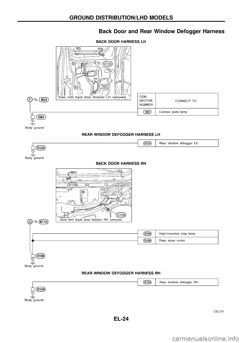
Back Door and Rear Window Defogger Harness
CEL731
GROUND DISTRIBUTION/LHD MODELS
EL-24
Page 39 of 326
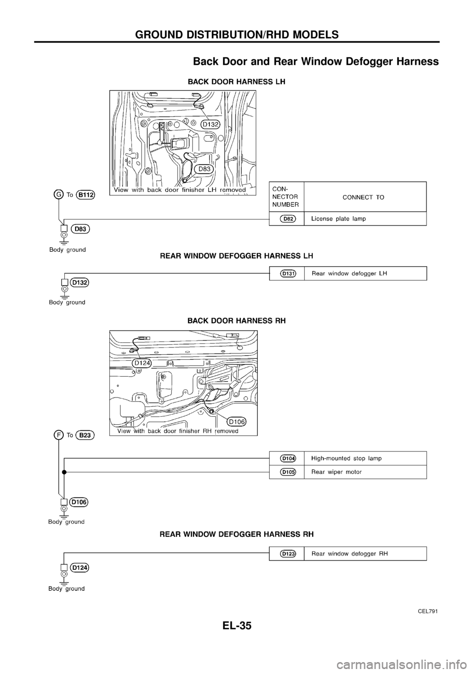
Back Door and Rear Window Defogger Harness
CEL791
GROUND DISTRIBUTION/RHD MODELS
EL-35
Page 42 of 326
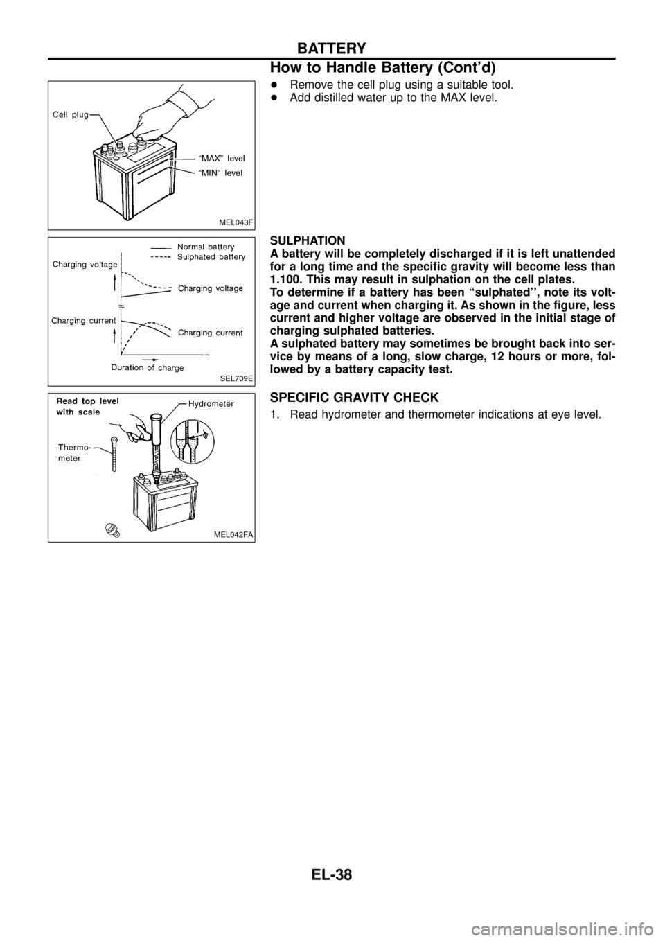
+Remove the cell plug using a suitable tool.
+Add distilled water up to the MAX level.
SULPHATION
A battery will be completely discharged if it is left unattended
for a long time and the speci®c gravity will become less than
1.100. This may result in sulphation on the cell plates.
To determine if a battery has been ``sulphated'', note its volt-
age and current when charging it. As shown in the ®gure, less
current and higher voltage are observed in the initial stage of
charging sulphated batteries.
A sulphated battery may sometimes be brought back into ser-
vice by means of a long, slow charge, 12 hours or more, fol-
lowed by a battery capacity test.
SPECIFIC GRAVITY CHECK
1. Read hydrometer and thermometer indications at eye level.
MEL043F
SEL709E
MEL042FA
BATTERY
How to Handle Battery (Cont'd)
EL-38
Page 54 of 326
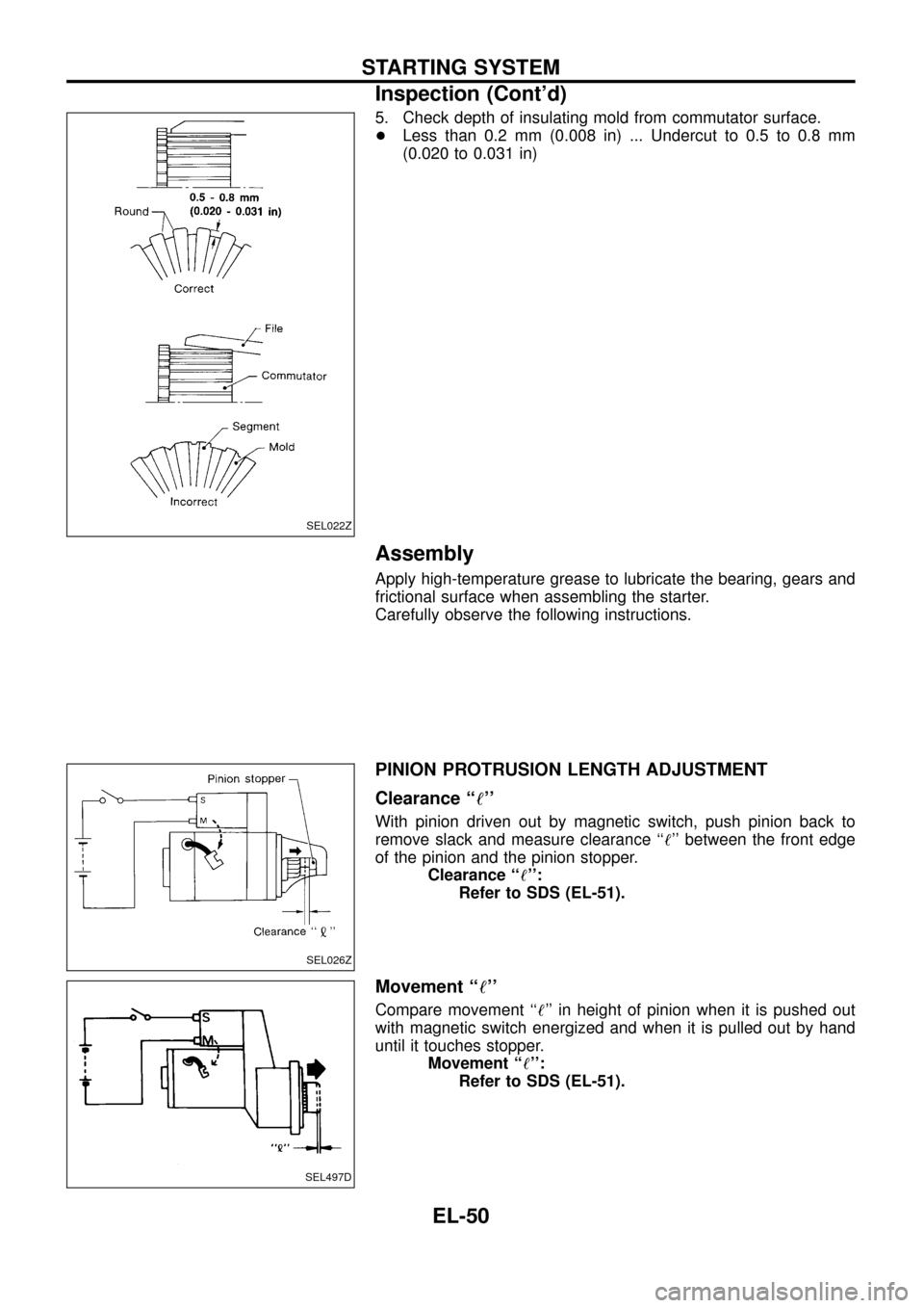
5. Check depth of insulating mold from commutator surface.
+Less than 0.2 mm (0.008 in) ... Undercut to 0.5 to 0.8 mm
(0.020 to 0.031 in)
Assembly
Apply high-temperature grease to lubricate the bearing, gears and
frictional surface when assembling the starter.
Carefully observe the following instructions.
PINION PROTRUSION LENGTH ADJUSTMENT
Clearance ``!''
With pinion driven out by magnetic switch, push pinion back to
remove slack and measure clearance ``!'' between the front edge
of the pinion and the pinion stopper.
Clearance ``!'':
Refer to SDS (EL-51).
Movement ``!''
Compare movement ``!'' in height of pinion when it is pushed out
with magnetic switch energized and when it is pulled out by hand
until it touches stopper.
Movement ``!'':
Refer to SDS (EL-51).
SEL022Z
SEL026Z
SEL497D
STARTING SYSTEM
Inspection (Cont'd)
EL-50
Page 67 of 326
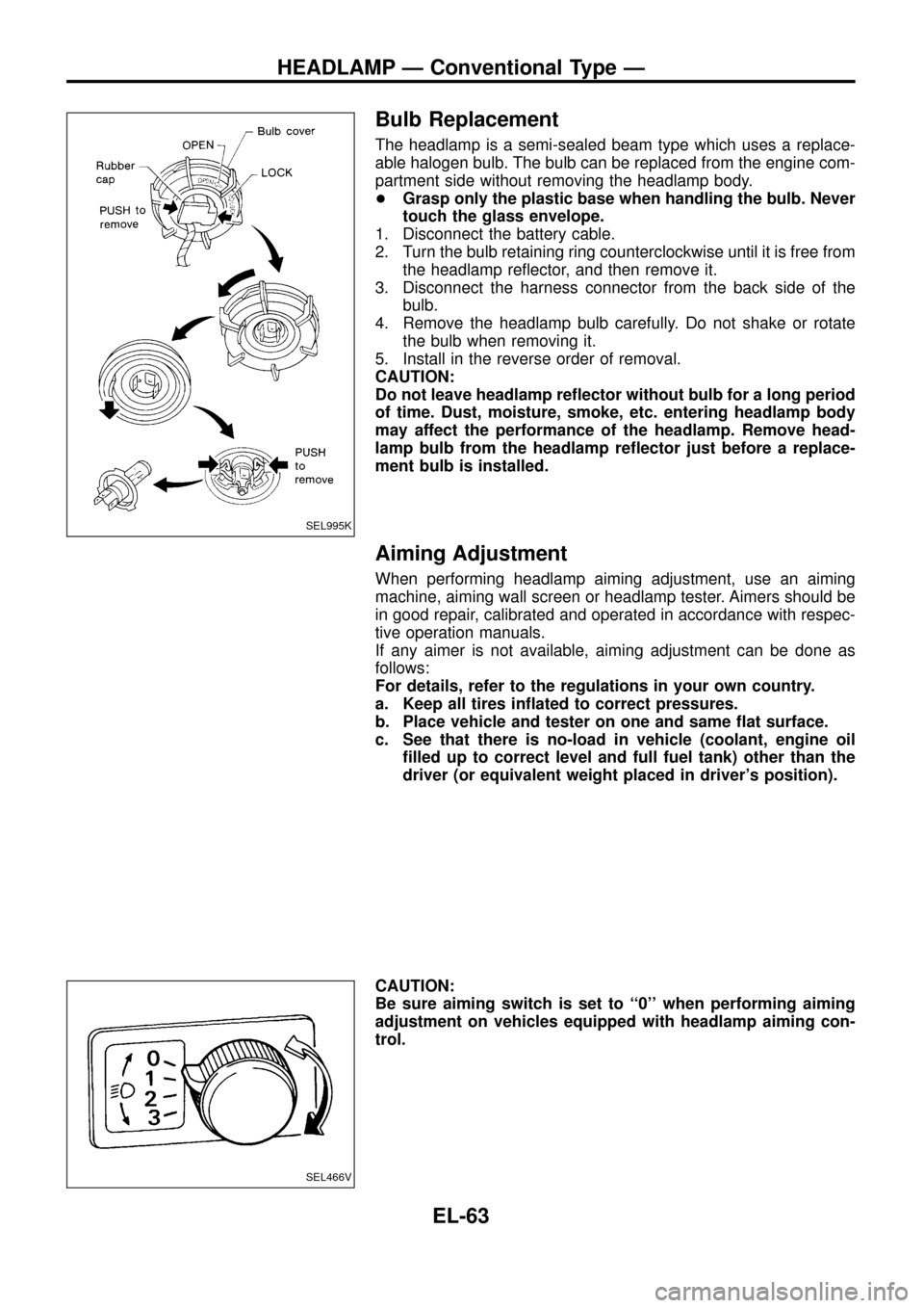
Bulb Replacement
The headlamp is a semi-sealed beam type which uses a replace-
able halogen bulb. The bulb can be replaced from the engine com-
partment side without removing the headlamp body.
+Grasp only the plastic base when handling the bulb. Never
touch the glass envelope.
1. Disconnect the battery cable.
2. Turn the bulb retaining ring counterclockwise until it is free from
the headlamp re¯ector, and then remove it.
3. Disconnect the harness connector from the back side of the
bulb.
4. Remove the headlamp bulb carefully. Do not shake or rotate
the bulb when removing it.
5. Install in the reverse order of removal.
CAUTION:
Do not leave headlamp re¯ector without bulb for a long period
of time. Dust, moisture, smoke, etc. entering headlamp body
may affect the performance of the headlamp. Remove head-
lamp bulb from the headlamp re¯ector just before a replace-
ment bulb is installed.
Aiming Adjustment
When performing headlamp aiming adjustment, use an aiming
machine, aiming wall screen or headlamp tester. Aimers should be
in good repair, calibrated and operated in accordance with respec-
tive operation manuals.
If any aimer is not available, aiming adjustment can be done as
follows:
For details, refer to the regulations in your own country.
a. Keep all tires in¯ated to correct pressures.
b. Place vehicle and tester on one and same ¯at surface.
c. See that there is no-load in vehicle (coolant, engine oil
®lled up to correct level and full fuel tank) other than the
driver (or equivalent weight placed in driver's position).
CAUTION:
Be sure aiming switch is set to ``0'' when performing aiming
adjustment on vehicles equipped with headlamp aiming con-
trol.
SEL995K
SEL466V
HEADLAMP Ð Conventional Type Ð
EL-63