Page 57 of 326

Trouble Diagnoses
Before conducting an alternator test, make sure that the battery is fully charged. A 30-volt voltmeter and suit-
able test probes are necessary for the test. The alternator can be checked easily by referring to the Inspec-
tion Table.
+Before starting, inspect the fusible link.
+Use fully charged battery.
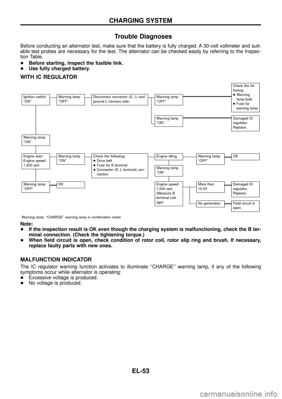
WITH IC REGULATOR
Check the fol-
lowing:
+Warning
lamp bulb
+Fuse for
warning lamp
Ignition switch
``ON''Warning lamp
``OFF''Disconnect connector (S, L) and
ground L harness side.Warning lamp
``OFF''
Warning lamp
``ON''Damaged IC
regulator.
Replace.
Warning lamp
``ON''
Engine start.
Engine speed:
1,500 rpmWarning lamp
``ON''Check the following:
+Drive belt
+Fuse for S terminal
+Connector (S, L terminal) con-
nectionEngine idlingWarning lamp
``OFF''OK
Warning lamp
``ON''
Warning lamp
``OFF''OKEngine speed:
1,500 rpm
(Measure B
terminal volt-
age)More than
15.5VDamaged IC
regulator.
Replace.
No generationField circuit is
open.
Warning lamp: ``CHARGE'' warning lamp in combination meter
Note:
+If the inspection result is OK even though the charging system is malfunctioning, check the B ter-
minal connection. (Check the tightening torque.)
+When ®eld circuit is open, check condition of rotor coil, rotor slip ring and brush. If necessary,
replace faulty parts with new ones.
MALFUNCTION INDICATOR
The IC regulator warning function activates to illuminate ``CHARGE'' warning lamp, if any of the following
symptoms occur while alternator is operating:
+Excessive voltage is produced.
+No voltage is produced.
CHARGING SYSTEM
EL-53
Page 58 of 326
Construction
Removal and Installation
CAUTION:
+Start service operation after removing the negative termi-
nal from the battery.
+Also remove the undercover, if equipped, before servicing.
Disassembly
REAR COVER
CAUTION:
Rear cover may be hard to remove because a ring is used to
lock outer race of rear bearing. To facilitate removal of rear
cover, heat just bearing box section with a 200W soldering
iron.
Do not use a heat gun, as it can damage diode assembly.
YEL783A
MEL610I
SEL032Z
CHARGING SYSTEM
EL-54
Page 59 of 326
REAR BEARING
CAUTION:
+Do not reuse rear bearing after removal. Replace with a
new one.
+Do not lubricate rear bearing outer race.
Inspection
ROTOR CHECK
1. Resistance test
Resistance: Refer to SDS (EL-56).
+Not within the speci®ed values ... Replace rotor.
2. Insulator test
+Continuity exists ... Replace rotor.
3. Check slip ring for wear.
Slip ring minimum outer diameter:
Refer to SDS (EL-56).
+Not within the speci®ed values ... Replace rotor.
BRUSH CHECK
1. Check smooth movement of brush.
+Not smooth ... Check brush holder and clean.
2. Check brush for wear.
+Replace brush if it is worn down to the limit line.
STATOR CHECK
1. Continuity test
+No continuity ... Replace stator.
2. Ground test
+Continuity exists ... Replace stator.
SEL033Z
SEL631DA
SEL108E
SEL109E
CHARGING SYSTEM
Disassembly (Cont'd)
EL-55
Page 60 of 326
Assembly
RING FITTING IN REAR BEARING
+Fix ring into groove in rear bearing so that it is as close to the
adjacent area as possible.
CAUTION:
Do not reuse rear bearing after removal.
REAR COVER INSTALLATION
1. Fit brush assembly, diode assembly, regulator assembly and
stator.
2. Push brushes up with ®ngers and install them to rotor.
Take care not to damage slip ring sliding surface.
Service Data and Speci®cations (SDS)
ALTERNATOR
TypeA3TA4399
MITSUBISHI
Applied model RD28
Nominal rating V-A 12-100
Ground polarity Negative
Minimum revolution under no-load
(When 13.5V is applied) rpmLess than 1,300
Hot output current
(When 13.5V is applied)
A/rpmMore than 35/1,300
More than 72/2,500
Regulated output voltage V 14.1 - 14.7
Minimum length of brush mm (in) 5 (0.20)
Brush spring pressure
N (g, oz)4.6 - 5.8
(470 - 590, 16.58 - 20.81)
Slip ring minimum outer diameter
mm (in)22.1 (0.870)
Rotor (Field coil) resistanceW2.1 - 2.5
SEL044Z
SEL048Z
SEL049Z
CHARGING SYSTEM
EL-56
Page 61 of 326
Check
RHD MODELS AND LHD MODELS
CEL781
COMBINATION SWITCH
EL-57
Page 62 of 326
Replacement
For removal and installation of spiral cable, refer to RS section
[``Installation Ð Air Bag Module and Spiral Cable'', ``SUPPLE-
MENTAL RESTRAINT SYSTEM (SRS)''].
+Each switch can be replaced without removing combination
switch base.
+To remove combination switch base, remove base attaching
screw.
+Before installing the steering wheel, align the steering wheel
guide pins with the screws which secure the combination switch
as shown in the left ®gure.
MEL304D
MEL326G
SEL151V
COMBINATION SWITCH
EL-58
Page 63 of 326
Check
WITH ASCD
CEL782
STEERING SWITCH
EL-59
Page 64 of 326
WITHOUT ASCD
CEL783
STEERING SWITCH
Check (Cont'd)
EL-60