1998 NISSAN PATROL Start
[x] Cancel search: StartPage 178 of 326
NATS Audio Link/LHD
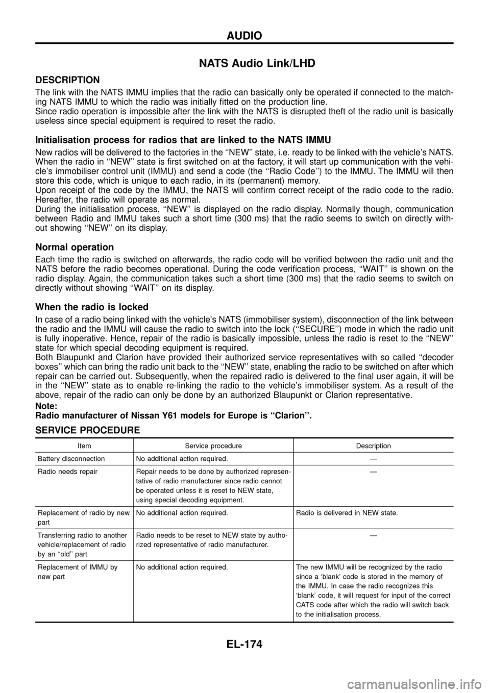
DESCRIPTION
The link with the NATS IMMU implies that the radio can basically only be operated if connected to the match-
ing NATS IMMU to which the radio was initially ®tted on the production line.
Since radio operation is impossible after the link with the NATS is disrupted theft of the radio unit is basically
useless since special equipment is required to reset the radio.
Initialisation process for radios that are linked to the NATS IMMU
New radios will be delivered to the factories in the ``NEW'' state, i.e. ready to be linked with the vehicle's NATS.
When the radio in ``NEW'' state is ®rst switched on at the factory, it will start up communication with the vehi-
cle's immobiliser control unit (IMMU) and send a code (the ``Radio Code'') to the IMMU. The IMMU will then
store this code, which is unique to each radio, in its (permanent) memory.
Upon receipt of the code by the IMMU, the NATS will con®rm correct receipt of the radio code to the radio.
Hereafter, the radio will operate as normal.
During the initialisation process, ``NEW'' is displayed on the radio display. Normally though, communication
between Radio and IMMU takes such a short time (300 ms) that the radio seems to switch on directly with-
out showing ``NEW'' on its display.
Normal operation
Each time the radio is switched on afterwards, the radio code will be veri®ed between the radio unit and the
NATS before the radio becomes operational. During the code veri®cation process, ``WAIT'' is shown on the
radio display. Again, the communication takes such a short time (300 ms) that the radio seems to switch on
directly without showing ``WAIT'' on its display.
When the radio is locked
In case of a radio being linked with the vehicle's NATS (immobiliser system), disconnection of the link between
the radio and the IMMU will cause the radio to switch into the lock (``SECURE'') mode in which the radio unit
is fully inoperative. Hence, repair of the radio is basically impossible, unless the radio is reset to the ``NEW''
state for which special decoding equipment is required.
Both Blaupunkt and Clarion have provided their authorized service representatives with so called ``decoder
boxes'' which can bring the radio unit back to the ``NEW'' state, enabling the radio to be switched on after which
repair can be carried out. Subsequently, when the repaired radio is delivered to the ®nal user again, it will be
in the ``NEW'' state as to enable re-linking the radio to the vehicle's immobiliser system. As a result of the
above, repair of the radio can only be done by an authorized Blaupunkt or Clarion representative.
Note:
Radio manufacturer of Nissan Y61 models for Europe is ``Clarion''.
SERVICE PROCEDURE
Item Service procedure Description
Battery disconnection No additional action required. Ð
Radio needs repair Repair needs to be done by authorized represen-
tative of radio manufacturer since radio cannot
be operated unless it is reset to NEW state,
using special decoding equipment.Ð
Replacement of radio by new
partNo additional action required. Radio is delivered in NEW state.
Transferring radio to another
vehicle/replacement of radio
by an ``old'' partRadio needs to be reset to NEW state by autho-
rized representative of radio manufacturer.Ð
Replacement of IMMU by
new partNo additional action required. The new IMMU will be recognized by the radio
since a `blank' code is stored in the memory of
the IMMU. In case the radio recognizes this
`blank' code, it will request for input of the correct
CATS code after which the radio will switch back
to the initialisation process.
AUDIO
EL-174
Page 184 of 326
Trouble Diagnoses
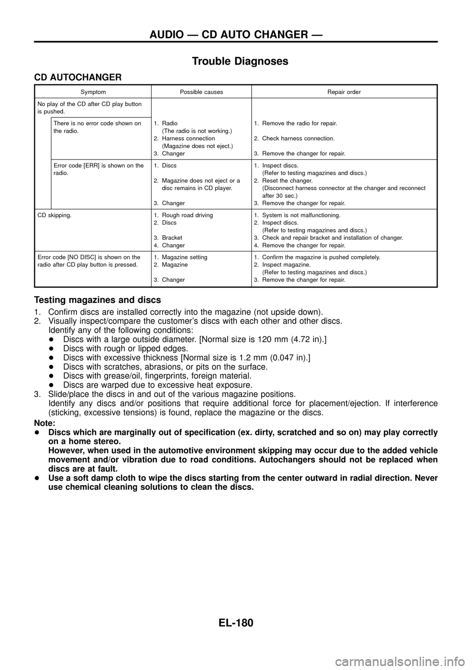
CD AUTOCHANGER
Symptom Possible causes Repair order
No play of the CD after CD play button
is pushed.
There is no error code shown on
the radio.1. Radio
(The radio is not working.)
2. Harness connection
(Magazine does not eject.)
3. Changer1. Remove the radio for repair.
2. Check harness connection.
3. Remove the changer for repair.
Error code [ERR] is shown on the
radio.1. Discs
2. Magazine does not eject or a
disc remains in CD player.
3. Changer1. Inspect discs.
(Refer to testing magazines and discs.)
2. Reset the changer.
(Disconnect harness connector at the changer and reconnect
after 30 sec.)
3. Remove the changer for repair.
CD skipping. 1. Rough road driving
2. Discs
3. Bracket
4. Changer1. System is not malfunctioning.
2. Inspect discs.
(Refer to testing magazines and discs.)
3. Check and repair bracket and installation of changer.
4. Remove the changer for repair.
Error code [NO DISC] is shown on the
radio after CD play button is pressed.1. Magazine setting
2. Magazine
3. Changer1. Con®rm the magazine is pushed completely.
2. Inspect magazine.
(Refer to testing magazines and discs.)
3. Remove the changer for repair.
Testing magazines and discs
1. Con®rm discs are installed correctly into the magazine (not upside down).
2. Visually inspect/compare the customer's discs with each other and other discs.
Identify any of the following conditions:
+Discs with a large outside diameter. [Normal size is 120 mm (4.72 in).]
+Discs with rough or lipped edges.
+Discs with excessive thickness [Normal size is 1.2 mm (0.047 in).]
+Discs with scratches, abrasions, or pits on the surface.
+Discs with grease/oil, ®ngerprints, foreign material.
+Discs are warped due to excessive heat exposure.
3. Slide/place the discs in and out of the various magazine positions.
Identify any discs and/or positions that require additional force for placement/ejection. If interference
(sticking, excessive tensions) is found, replace the magazine or the discs.
Note:
+Discs which are marginally out of speci®cation (ex. dirty, scratched and so on) may play correctly
on a home stereo.
However, when used in the automotive environment skipping may occur due to the added vehicle
movement and/or vibration due to road conditions. Autochangers should not be replaced when
discs are at fault.
+Use a soft damp cloth to wipe the discs starting from the center outward in radial direction. Never
use chemical cleaning solutions to clean the discs.
AUDIO Ð CD AUTO CHANGER Ð
EL-180
Page 200 of 326
![NISSAN PATROL 1998 Y61 / 5.G Electrical System Workshop Manual System Description
With ignition switch in ON or START position, power is supplied
+through 7.5A fuse [No.
8, located in the fuse block (J/B)]
+to power window relay terminalj
1.
The power window rela NISSAN PATROL 1998 Y61 / 5.G Electrical System Workshop Manual System Description
With ignition switch in ON or START position, power is supplied
+through 7.5A fuse [No.
8, located in the fuse block (J/B)]
+to power window relay terminalj
1.
The power window rela](/manual-img/5/616/w960_616-199.png)
System Description
With ignition switch in ON or START position, power is supplied
+through 7.5A fuse [No.
8, located in the fuse block (J/B)]
+to power window relay terminalj
1.
The power window relay is energized and power is supplied
+through power window relay terminalj
5
+to power window main switch terminalj1,
+to power window sub switch terminalj
5.
MANUAL OPERATION
NOTE:
Numbers in parentheses are terminal numbers, when power window switch is pressed in the UP and DOWN
positions respectively.
Driver side
When the driver side switch in the power window main switch is pressed in the up position, power is supplied
+to driver side power window regulator terminal (j
2,j1)
+through power window main switch terminal (j
9,j8).
Ground is supplied
+to driver side power window regulator terminal (j
1,j2)
+through power window main switch terminal (j
8,j9).
Then, the motor raises or lowers the window until the switch is released.
Passenger side
MAIN SWITCH OPERATION
Power is supplied
+through power window main switch (j
5,j6)
+to front power window sub-switch (j
3,j4).
The subsequent operation is the same as the sub-switch operation.
SUB-SWITCH OPERATION
Power is supplied
+through front power window sub-switch (j
1,j2)
+to passenger side power window regulator (j
2,j1).
Ground is supplied
+to passenger side power window regulator (j
1,j2)
+through front power window sub-switch (j
2,j1)
+to front power window sub-switch (j
4,j3)
+through power window main switch (j
6,j5).
Then, the motor raises or lowers the window until the switch is released.
Rear door
Rear door windows will raise and lower in the same manner as passenger side door window.
AUTO OPERATION
The power window AUTO feature enables the driver to open or close the driver's window without holding the
window switch in the respective position.
When the AUTO switch in the main switch is pressed and released, the driver's window will travel to the fully
open or closed position.
POWER WINDOW LOCK
The power window lock is designed to lock operation of all windows except for driver's door window.
When the lock switch is pressed to lock position, ground of the sub-switches in the power window main switch
is disconnected. This prevents the power window motors from operating.
POWER WINDOW
EL-196
Page 228 of 326
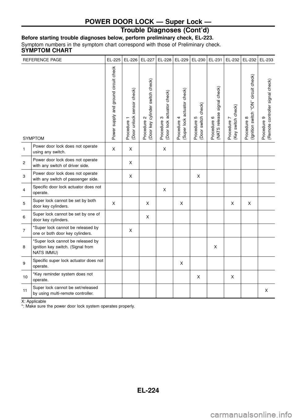
Before starting trouble diagnoses below, perform preliminary check, EL-223.
Symptom numbers in the symptom chart correspond with those of Preliminary check.
SYMPTOM CHART
REFERENCE PAGE EL-225 EL-226 EL-227 EL-228 EL-229 EL-230 EL-231 EL-232 EL-232 EL-233
SYMPTOM
Power supply and ground circuit check
Procedure 1
(Door unlock sensor check)
Procedure 2
(Door key cylinder switch check)
Procedure 3
(Door lock actuator check)
Procedure 4
(Super lock actuator check)
Procedure 5
(Door switch check)
Procedure 6
(NATS release signal check)
Procedure 7
(Key switch check)
Procedure 8
(Ignition switch ``ON'' circuit check)
Procedure 9
(Remote controller signal check)
1Power door lock does not operate
using any switch.XX X
2Power door lock does not operate
with any switch of driver side.X
3Power door lock does not operate
with any switch of passenger side.XX
4Speci®c door lock actuator does not
operate.X
5Super lock cannot be set by both
door key cylinders.XXX XX
6Super lock cannot be set by one of
door key cylinders.X
7*Super lock cannot be released by
one or both door key cylinders.X
8*Super lock cannot be released by
ignition key switch. (Signal from
NATS IMMU)X
9Speci®c super lock actuator does not
operate.X
10*Key reminder system does not
operate.XX
11Super lock cannot be set/released
by using multi-remote controller.X
X: Applicable
*: Make sure the power door lock system operates properly.
POWER DOOR LOCK Ð Super Lock Ð
Trouble Diagnoses (Cont'd)
EL-224
Page 235 of 326
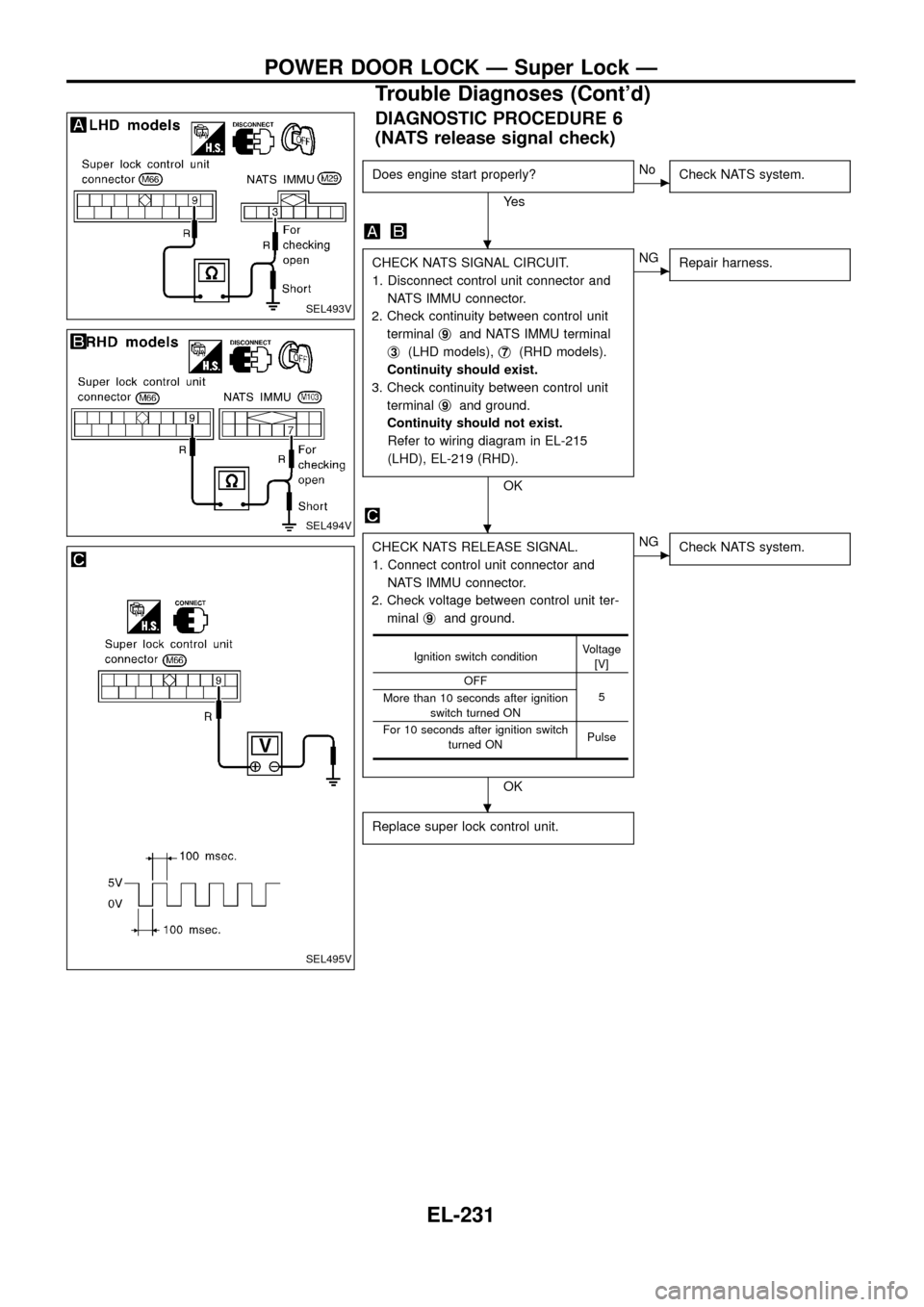
DIAGNOSTIC PROCEDURE 6
(NATS release signal check)
Does engine start properly?
Ye s
cNo
Check NATS system.
CHECK NATS SIGNAL CIRCUIT.
1. Disconnect control unit connector and
NATS IMMU connector.
2. Check continuity between control unit
terminalj
9and NATS IMMU terminal
j
3(LHD models),j7(RHD models).
Continuity should exist.
3. Check continuity between control unit
terminalj
9and ground.
Continuity should not exist.
Refer to wiring diagram in EL-215
(LHD), EL-219 (RHD).
OK
cNG
Repair harness.
CHECK NATS RELEASE SIGNAL.
1. Connect control unit connector and
NATS IMMU connector.
2. Check voltage between control unit ter-
minalj
9and ground.
OK
cNG
Check NATS system.
Replace super lock control unit.
Ignition switch conditionVoltage
[V]
OFF
5
More than 10 seconds after ignition
switch turned ON
For 10 seconds after ignition switch
turned ONPulse
SEL493V
SEL494V
SEL495V
.
.
.
POWER DOOR LOCK Ð Super Lock Ð
Trouble Diagnoses (Cont'd)
EL-231
Page 244 of 326
System Description
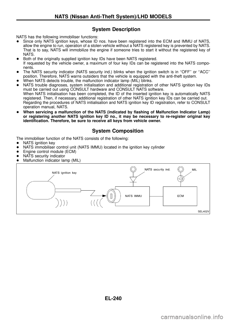
NATS has the following immobiliser functions:
+Since only NATS ignition keys, whose ID nos. have been registered into the ECM and IMMU of NATS,
allow the engine to run, operation of a stolen vehicle without a NATS registered key is prevented by NATS.
That is to say, NATS will immobilize the engine if someone tries to start it without the registered key of
NATS.
+Both of the originally supplied ignition key IDs have been NATS registered.
If requested by the vehicle owner, a maximum of four key IDs can be registered into the NATS compo-
nents.
+The NATS security indicator (NATS security ind.) blinks when the ignition switch is in ``OFF'' or ``ACC''
position. Therefore, NATS warns outsiders that the vehicle is equipped with the anti-theft system.
+When NATS detects trouble, the malfunction indicator lamp (MIL) blinks.
+NATS trouble diagnoses, system initialisation and additional registration of other NATS ignition key IDs
must be carried out using CONSULT hardware and CONSULT NATS software.
When NATS initialisation has been completed, the ID of the inserted ignition key is automatically NATS
registered. Then, if necessary, additional registration of other NATS ignition key IDs can be carried out.
Regarding the procedures of NATS initialisation and NATS ignition key ID registration, refer to CONSULT
operation manual, NATS.
+When servicing a malfunction of the NATS (indicated by ¯ashing of Malfunction Indicator Lamp)
or registering another NATS ignition key ID no., it may be necessary to re-register original key
identi®cation. Therefore, be sure to receive all keys from vehicle owner.
System Composition
The immobiliser function of the NATS consists of the following:
+NATS ignition key
+NATS immobiliser control unit (NATS IMMU) located in the ignition key cylinder
+Engine control module (ECM)
+NATS security indicator
+Malfunction indicator lamp (MIL)
SEL402V
NATS (Nissan Anti-Theft System)/LHD MODELS
EL-240
Page 246 of 326
CONSULT
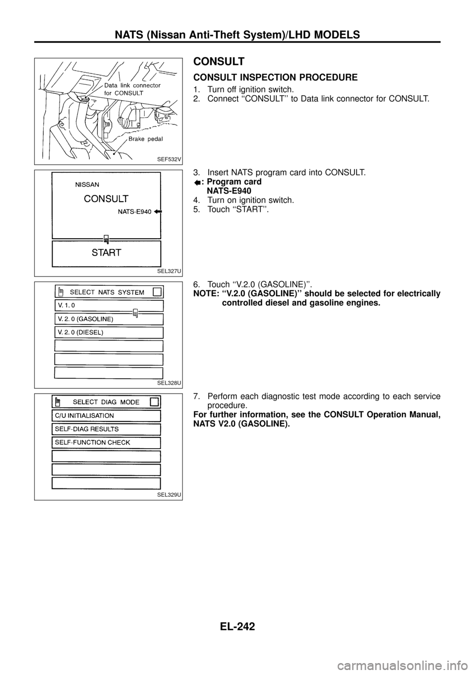
CONSULT INSPECTION PROCEDURE
1. Turn off ignition switch.
2. Connect ``CONSULT'' to Data link connector for CONSULT.
3. Insert NATS program card into CONSULT.
: Program card
NATS-E940
4. Turn on ignition switch.
5. Touch ``START''.
6. Touch ``V.2.0 (GASOLINE)''.
NOTE: ``V.2.0 (GASOLINE)'' should be selected for electrically
controlled diesel and gasoline engines.
7. Perform each diagnostic test mode according to each service
procedure.
For further information, see the CONSULT Operation Manual,
NATS V2.0 (GASOLINE).
SEF532V
SEL327U
SEL328U
SEL329U
NATS (Nissan Anti-Theft System)/LHD MODELS
EL-242
Page 247 of 326
CONSULT DIAGNOSTIC TEST MODE FUNCTION
CONSULT DIAGNOSTIC TEST
MODEDescription
C/U INITIALIZATION When replacing any of the following three components, C/U initialization is necessary.
[NATS ignition key/IMMU/ECM]
SELF-FUNCTION CHECK ECM checks its own NATS communication interface by itself.
SELF-DIAGNOSTIC RESULTS Detected items (screen terms) are as shown in the chart below.
NOTE:
When any initialisation is performed, all ID previously registered will be erased. So all NATS ignition
keys must be registered again.
The engine cannot be started with an unregistered key. In this case, the system may show ``DIFFER-
ENCE OF KEY'' or ``LOCK MODE'' as a self-diagnostic result on the CONSULT screen.
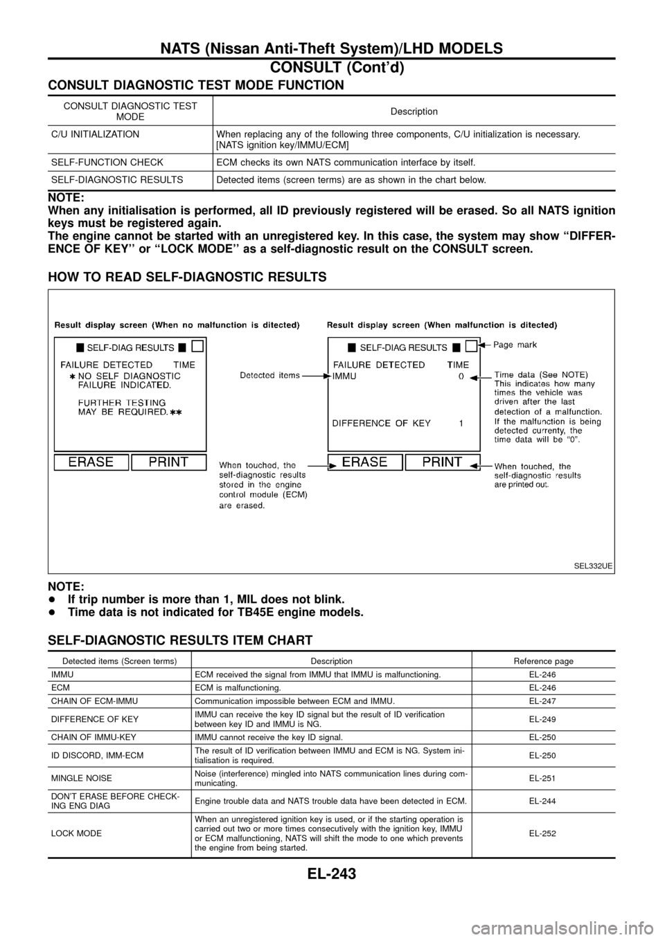
HOW TO READ SELF-DIAGNOSTIC RESULTS
NOTE:
+If trip number is more than 1, MIL does not blink.
+Time data is not indicated for TB45E engine models.
SELF-DIAGNOSTIC RESULTS ITEM CHART
Detected items (Screen terms) Description Reference page
IMMU ECM received the signal from IMMU that IMMU is malfunctioning. EL-246
ECM ECM is malfunctioning. EL-246
CHAIN OF ECM-IMMU Communication impossible between ECM and IMMU. EL-247
DIFFERENCE OF KEYIMMU can receive the key ID signal but the result of ID veri®cation
between key ID and IMMU is NG.EL-249
CHAIN OF IMMU-KEY IMMU cannot receive the key ID signal. EL-250
ID DISCORD, IMM-ECMThe result of ID veri®cation between IMMU and ECM is NG. System ini-
tialisation is required.EL-250
MINGLE NOISENoise (interference) mingled into NATS communication lines during com-
municating.EL-251
DON'T ERASE BEFORE CHECK-
ING ENG DIAGEngine trouble data and NATS trouble data have been detected in ECM. EL-244
LOCK MODEWhen an unregistered ignition key is used, or if the starting operation is
carried out two or more times consecutively with the ignition key, IMMU
or ECM malfunctioning, NATS will shift the mode to one which prevents
the engine from being started.EL-252
SEL332UE
NATS (Nissan Anti-Theft System)/LHD MODELS
CONSULT (Cont'd)
EL-243