1998 NISSAN PATROL Ignition switch
[x] Cancel search: Ignition switchPage 187 of 326
Trouble Diagnoses
POWER ANTENNA
Symptom Possible causes Repair order
Power antenna does not oper-
ate.1. 10A fuse
2. Radio signal
3. Grounds
E25andE40
1. Check 10A fuse (No.56, located in fuse and fusible link
box). Verify that battery positive voltage is present at termi-
nalj
1: LHD,j2: RHD of power antenna.
2. Turn ignition switch and radio ON. Verify that battery positive
voltage is present at terminalj
3: LHD,j1: RHD of power
antenna.
3. Check grounds
E25andE40.
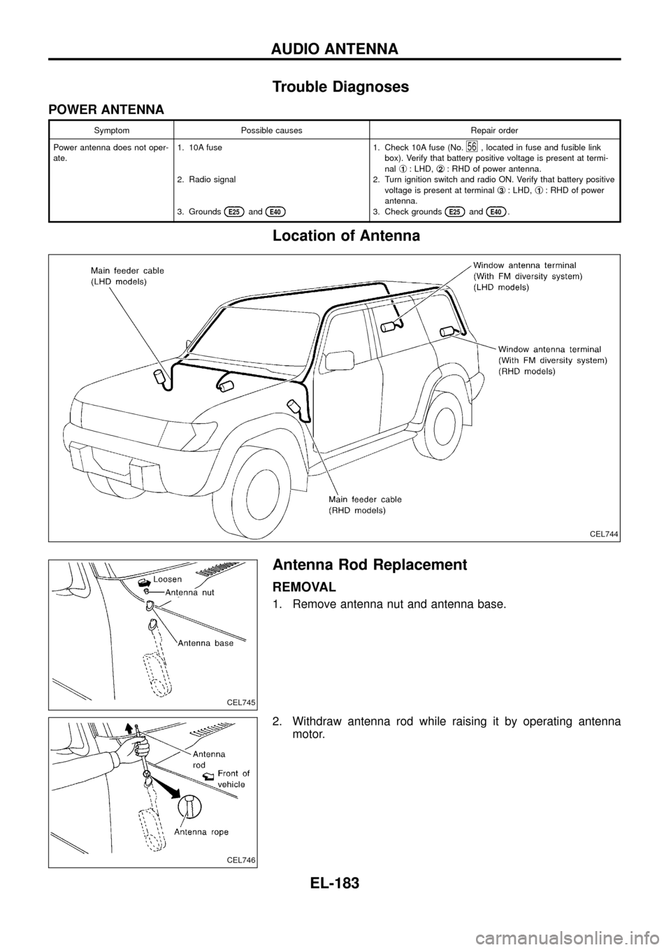
Location of Antenna
Antenna Rod Replacement
REMOVAL
1. Remove antenna nut and antenna base.
2. Withdraw antenna rod while raising it by operating antenna
motor.
CEL744
CEL745
CEL746
AUDIO ANTENNA
EL-183
Page 200 of 326
![NISSAN PATROL 1998 Y61 / 5.G Electrical System Workshop Manual System Description
With ignition switch in ON or START position, power is supplied
+through 7.5A fuse [No.
8, located in the fuse block (J/B)]
+to power window relay terminalj
1.
The power window rela NISSAN PATROL 1998 Y61 / 5.G Electrical System Workshop Manual System Description
With ignition switch in ON or START position, power is supplied
+through 7.5A fuse [No.
8, located in the fuse block (J/B)]
+to power window relay terminalj
1.
The power window rela](/manual-img/5/616/w960_616-199.png)
System Description
With ignition switch in ON or START position, power is supplied
+through 7.5A fuse [No.
8, located in the fuse block (J/B)]
+to power window relay terminalj
1.
The power window relay is energized and power is supplied
+through power window relay terminalj
5
+to power window main switch terminalj1,
+to power window sub switch terminalj
5.
MANUAL OPERATION
NOTE:
Numbers in parentheses are terminal numbers, when power window switch is pressed in the UP and DOWN
positions respectively.
Driver side
When the driver side switch in the power window main switch is pressed in the up position, power is supplied
+to driver side power window regulator terminal (j
2,j1)
+through power window main switch terminal (j
9,j8).
Ground is supplied
+to driver side power window regulator terminal (j
1,j2)
+through power window main switch terminal (j
8,j9).
Then, the motor raises or lowers the window until the switch is released.
Passenger side
MAIN SWITCH OPERATION
Power is supplied
+through power window main switch (j
5,j6)
+to front power window sub-switch (j
3,j4).
The subsequent operation is the same as the sub-switch operation.
SUB-SWITCH OPERATION
Power is supplied
+through front power window sub-switch (j
1,j2)
+to passenger side power window regulator (j
2,j1).
Ground is supplied
+to passenger side power window regulator (j
1,j2)
+through front power window sub-switch (j
2,j1)
+to front power window sub-switch (j
4,j3)
+through power window main switch (j
6,j5).
Then, the motor raises or lowers the window until the switch is released.
Rear door
Rear door windows will raise and lower in the same manner as passenger side door window.
AUTO OPERATION
The power window AUTO feature enables the driver to open or close the driver's window without holding the
window switch in the respective position.
When the AUTO switch in the main switch is pressed and released, the driver's window will travel to the fully
open or closed position.
POWER WINDOW LOCK
The power window lock is designed to lock operation of all windows except for driver's door window.
When the lock switch is pressed to lock position, ground of the sub-switches in the power window main switch
is disconnected. This prevents the power window motors from operating.
POWER WINDOW
EL-196
Page 207 of 326
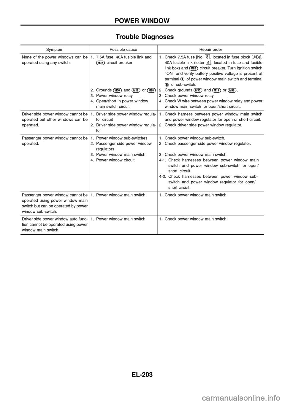
Trouble Diagnoses
Symptom Possible cause Repair order
None of the power windows can be
operated using any switch.1. 7.5A fuse, 40A fusible link and
M92circuit breaker
2. Grounds
M30andM19orM98
3. Power window relay
4. Open/short in power window
main switch circuit1. Check 7.5A fuse [No.
8, located in fuse block (J/B)],
40A fusible link (letter
e, located in fuse and fusible
link box) and
M92circuit breaker. Turn ignition switch
``ON'' and verify battery positive voltage is present at
terminalj
1of power window main switch and terminal
j
5of sub-switch.
2. Check grounds
M30andM19orM98.
3. Check power window relay.
4. Check W wire between power window relay and power
window main switch for open/short circuit.
Driver side power window cannot be
operated but other windows can be
operated.1. Driver side power window regula-
tor circuit
2. Driver side power window regula-
tor1. Check harness between power window main switch
and power window regulator for open or short circuit.
2. Check driver side power window regulator.
Passenger power window cannot be
operated.1. Power window sub-switches
2. Passenger side power window
regulators
3. Power window main switch
4. Power window circuit1. Check power window sub-switch.
2. Check passenger side power window regulator.
3. Check power window main switch.
4-1. Check harnesses between power window main
switch and power window sub-switch for open/
short circuit.
4-2. Check harnesses between power window sub-
switch and power window regulator for open/
short circuit.
Passenger power window cannot be
operated using power window main
switch but can be operated by power
window sub-switch.1. Power window main switch 1. Check power window main switch.
Driver side power window auto func-
tion cannot be operated using power
window main switch.1. Power window main switch 1. Check power window main switch.
POWER WINDOW
EL-203
Page 211 of 326
Trouble Diagnosis
SYMPTOM CHART
REFERENCE PAGE EL-207 EL-208 EL-209 EL-210
SYMPTOM
MAIN POWER SUPPLY AND GROUND CIRCUIT CHECK
DIAGNOSTIC PROCEDURE 1
(Door lock/unlock switch check)
DIAGNOSTIC PROCEDURE 2
(Door lock actuator check)
DIAGNOSTIC PROCEDURE 3
(Driver side door lock switch check)
None of the doors lock/unlock when operat-
ing any switch.XX
One or more doors are not locked and/or
unlocked.X
Door lock/unlock switch does not operate. X
Door knob lock switch/key cylinder on driv-
er's door does not operate.X
Driver side door does not lock/unlock when
operating remote controller. (With multi-re-
mote control system)X
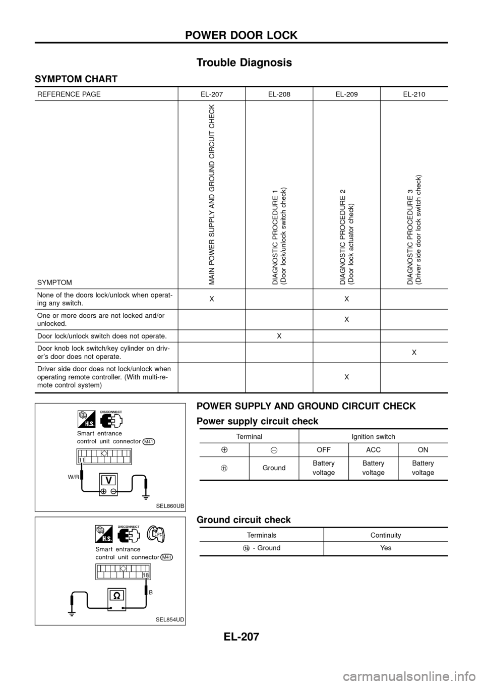
POWER SUPPLY AND GROUND CIRCUIT CHECK
Power supply circuit check
Terminal Ignition switch
Å@OFF ACC ON
j
11GroundBattery
voltageBattery
voltageBattery
voltage
Ground circuit check
Terminals Continuity
j
18- Ground Yes
SEL860UB
SEL854UD
POWER DOOR LOCK
EL-207
Page 216 of 326
System Description
OUTLINE
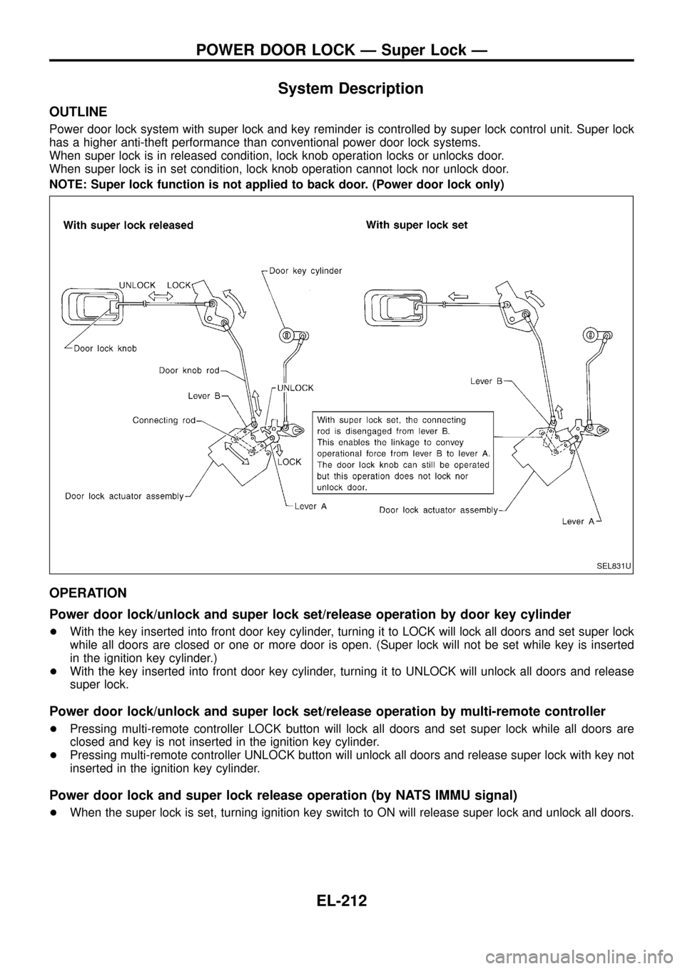
Power door lock system with super lock and key reminder is controlled by super lock control unit. Super lock
has a higher anti-theft performance than conventional power door lock systems.
When super lock is in released condition, lock knob operation locks or unlocks door.
When super lock is in set condition, lock knob operation cannot lock nor unlock door.
NOTE: Super lock function is not applied to back door. (Power door lock only)
OPERATION
Power door lock/unlock and super lock set/release operation by door key cylinder
+With the key inserted into front door key cylinder, turning it to LOCK will lock all doors and set super lock
while all doors are closed or one or more door is open. (Super lock will not be set while key is inserted
in the ignition key cylinder.)
+With the key inserted into front door key cylinder, turning it to UNLOCK will unlock all doors and release
super lock.
Power door lock/unlock and super lock set/release operation by multi-remote controller
+Pressing multi-remote controller LOCK button will lock all doors and set super lock while all doors are
closed and key is not inserted in the ignition key cylinder.
+Pressing multi-remote controller UNLOCK button will unlock all doors and release super lock with key not
inserted in the ignition key cylinder.
Power door lock and super lock release operation (by NATS IMMU signal)
+When the super lock is set, turning ignition key switch to ON will release super lock and unlock all doors.
SEL831U
POWER DOOR LOCK Ð Super Lock Ð
EL-212
Page 217 of 326
Power door lock/unlock operation by lock knob
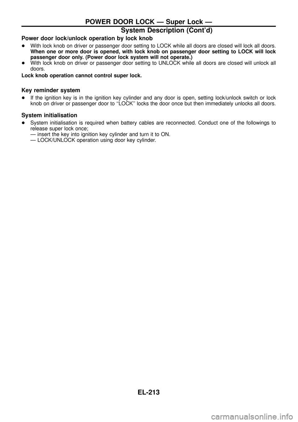
+With lock knob on driver or passenger door setting to LOCK while all doors are closed will lock all doors.
When one or more door is opened, with lock knob on passenger door setting to LOCK will lock
passenger door only. (Power door lock system will not operate.)
+With lock knob on driver or passenger door setting to UNLOCK while all doors are closed will unlock all
doors.
Lock knob operation cannot control super lock.
Key reminder system
+If the ignition key is in the ignition key cylinder and any door is open, setting lock/unlock switch or lock
knob on driver or passenger door to ``LOCK'' locks the door once but then immediately unlocks all doors.
System initialisation
+System initialisation is required when battery cables are reconnected. Conduct one of the followings to
release super lock once;
Ð insert the key into ignition key cylinder and turn it to ON.
Ð LOCK/UNLOCK operation using door key cylinder.
POWER DOOR LOCK Ð Super Lock Ð
System Description (Cont'd)
EL-213
Page 227 of 326
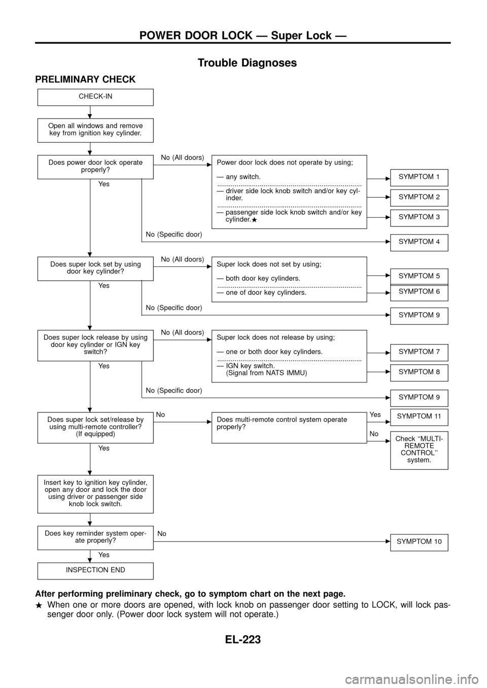
Trouble Diagnoses
PRELIMINARY CHECK
CHECK-IN
Open all windows and remove
key from ignition key cylinder.
Does power door lock operate
properly?
Ye s
cNo (All doors)
Power door lock does not operate by using;
Ð any switch.
...........................................................................
Ð driver side lock knob switch and/or key cyl-
inder.
...........................................................................
Ð passenger side lock knob switch and/or key
cylinder..
cSYMPTOM 1
cSYMPTOM 2
cSYMPTOM 3
cNo (Speci®c door)
SYMPTOM 4
Does super lock set by using
door key cylinder?
Ye s
cNo (All doors)
Super lock does not set by using;
Ð both door key cylinders.
...........................................................................
Ð one of door key cylinders.
cSYMPTOM 5
cSYMPTOM 6
cNo (Speci®c door)
SYMPTOM 9
Does super lock release by using
door key cylinder or IGN key
switch?
Ye s
cNo (All doors)
Super lock does not release by using;
Ð one or both door key cylinders.
...........................................................................
Ð IGN key switch.
(Signal from NATS IMMU)
cSYMPTOM 7
cSYMPTOM 8
cNo (Speci®c door)
SYMPTOM 9
Does super lock set/release by
using multi-remote controller?
(If equipped)
Ye s
cNo
Does multi-remote control system operate
properly?cYe s
SYMPTOM 11
cNo
Check ``MULTI-
REMOTE
CONTROL''
system.
Insert key to ignition key cylinder,
open any door and lock the door
using driver or passenger side
knob lock switch.
Does key reminder system oper-
ate properly?
Ye s
cNo
SYMPTOM 10
INSPECTION END
After performing preliminary check, go to symptom chart on the next page.
.When one or more doors are opened, with lock knob on passenger door setting to LOCK, will lock pas-
senger door only. (Power door lock system will not operate.)
.
.
.
.
.
.
.
.
POWER DOOR LOCK Ð Super Lock Ð
EL-223
Page 228 of 326
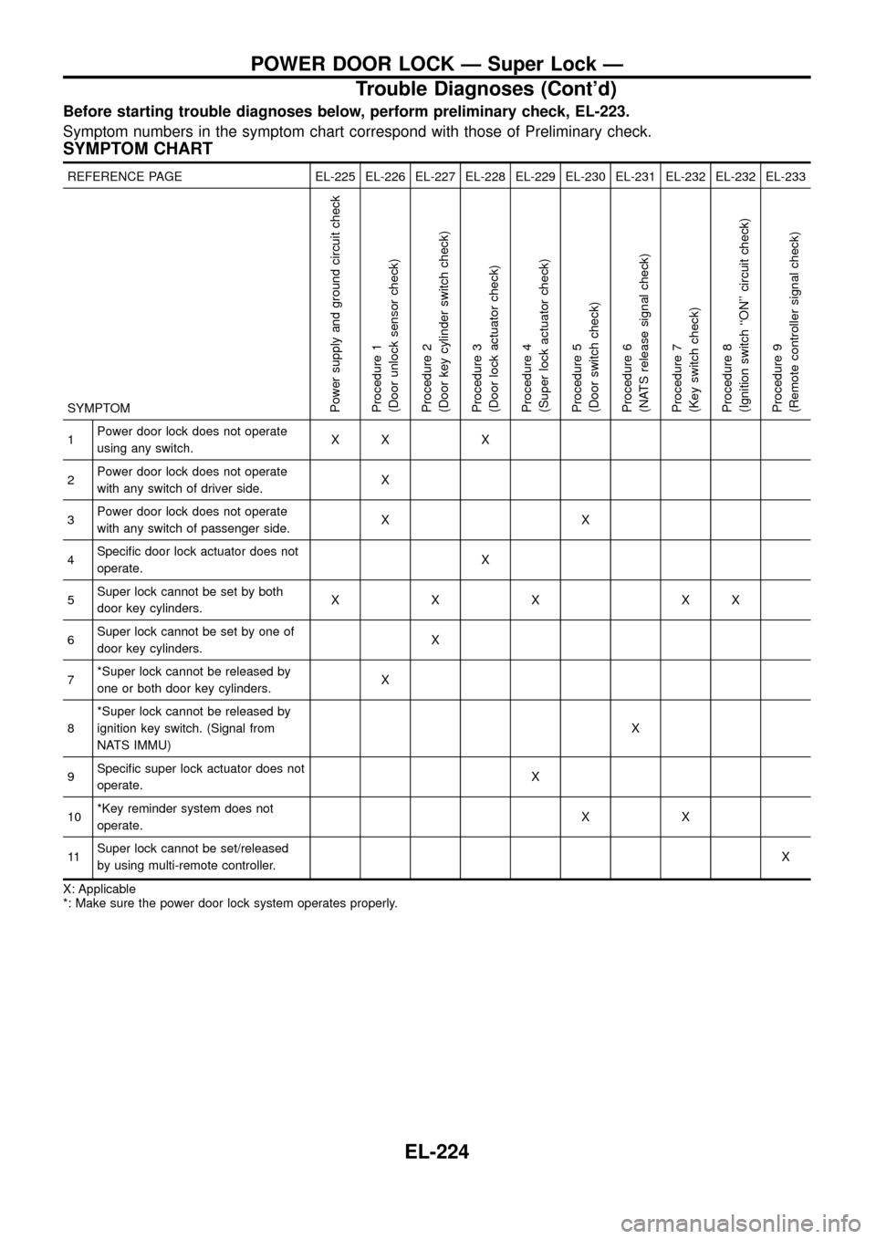
Before starting trouble diagnoses below, perform preliminary check, EL-223.
Symptom numbers in the symptom chart correspond with those of Preliminary check.
SYMPTOM CHART
REFERENCE PAGE EL-225 EL-226 EL-227 EL-228 EL-229 EL-230 EL-231 EL-232 EL-232 EL-233
SYMPTOM
Power supply and ground circuit check
Procedure 1
(Door unlock sensor check)
Procedure 2
(Door key cylinder switch check)
Procedure 3
(Door lock actuator check)
Procedure 4
(Super lock actuator check)
Procedure 5
(Door switch check)
Procedure 6
(NATS release signal check)
Procedure 7
(Key switch check)
Procedure 8
(Ignition switch ``ON'' circuit check)
Procedure 9
(Remote controller signal check)
1Power door lock does not operate
using any switch.XX X
2Power door lock does not operate
with any switch of driver side.X
3Power door lock does not operate
with any switch of passenger side.XX
4Speci®c door lock actuator does not
operate.X
5Super lock cannot be set by both
door key cylinders.XXX XX
6Super lock cannot be set by one of
door key cylinders.X
7*Super lock cannot be released by
one or both door key cylinders.X
8*Super lock cannot be released by
ignition key switch. (Signal from
NATS IMMU)X
9Speci®c super lock actuator does not
operate.X
10*Key reminder system does not
operate.XX
11Super lock cannot be set/released
by using multi-remote controller.X
X: Applicable
*: Make sure the power door lock system operates properly.
POWER DOOR LOCK Ð Super Lock Ð
Trouble Diagnoses (Cont'd)
EL-224