1998 LINCOLN CONTINENTAL ECO mode
[x] Cancel search: ECO modePage 5 of 176

NEXT
MODEVOL
TEMP FAN
000000.0
SYSTEM
DRIVER ID
MENU
TRIP
RESET
SELECT
DISPLAY
DTE ECON
VEHICLE HANDLING
NITNOCLATNE
VOL
PUSH ON
TAPE
MUTESEEK
TUNE
AM
FM
REW
FFSIDE 1 2
COMP
SHUFF
EXT
OFFMAX
A/CCDEJ
RDS
SCAN AUTO
AUTO
123
4
56
FRONT
REAR
BASS
TREBSELBAL
FADE
HIHI
OFF OFFBACK
BOTH BOTHBACK00
HEATED SEATS
Electronic sound system
control
(pg. 35)Message Center
(pg. 12)Clock
(pg. 33)Electronic sound
system; refer to
Audio Guide
(pg. 33)
Climate control
systems
(pg. 27) Heated seat
control*
(pg. 73) Climate controls*
(pg. 36)
*if equipped
Instrumentation
5
Page 16 of 176
RESET
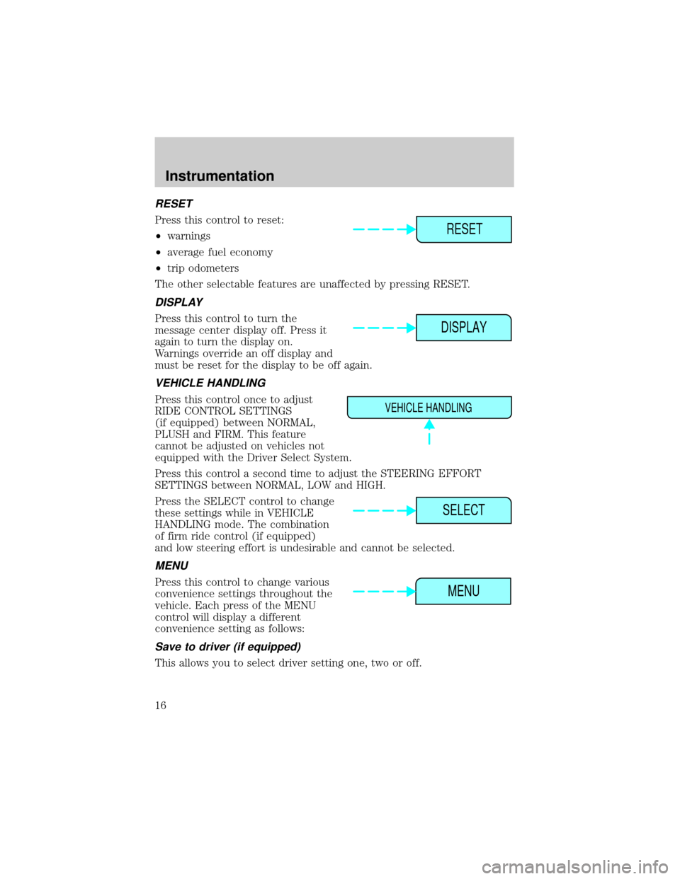
Press this control to reset:
²warnings
²average fuel economy
²trip odometers
The other selectable features are unaffected by pressing RESET.
DISPLAY
Press this control to turn the
message center display off. Press it
again to turn the display on.
Warnings override an off display and
must be reset for the display to be off again.
VEHICLE HANDLING
Press this control once to adjust
RIDE CONTROL SETTINGS
(if equipped) between NORMAL,
PLUSH and FIRM. This feature
cannot be adjusted on vehicles not
equipped with the Driver Select System.
Press this control a second time to adjust the STEERING EFFORT
SETTINGS between NORMAL, LOW and HIGH.
Press the SELECT control to change
these settings while in VEHICLE
HANDLING mode. The combination
of firm ride control (if equipped)
and low steering effort is undesirable and cannot be selected.
MENU
Press this control to change various
convenience settings throughout the
vehicle. Each press of the MENU
control will display a different
convenience setting as follows:
Save to driver (if equipped)
This allows you to select driver setting one, two or off.
RESET
DISPLAY
VEHICLE HANDLING
SELECT
MENU
Instrumentation
16
Page 30 of 176
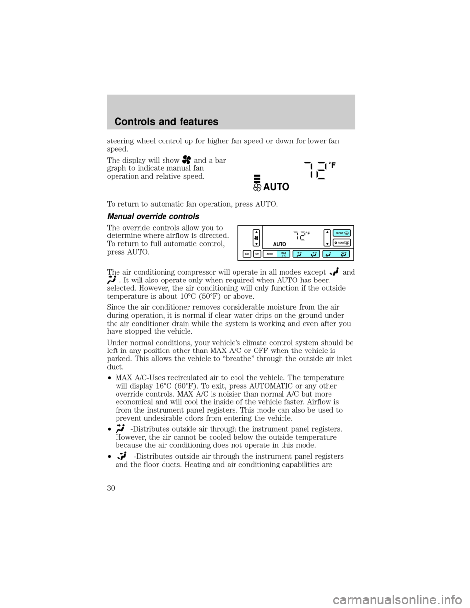
steering wheel control up for higher fan speed or down for lower fan
speed.
The display will show
and a bar
graph to indicate manual fan
operation and relative speed.
To return to automatic fan operation, press AUTO.
Manual override controls
The override controls allow you to
determine where airflow is directed.
To return to full automatic control,
press AUTO.
The air conditioning compressor will operate in all modes except
and
. It will also operate only when required when AUTO has been
selected. However, the air conditioning will only function if the outside
temperature is about 10ÉC (50ÉF) or above.
Since the air conditioner removes considerable moisture from the air
during operation, it is normal if clear water drips on the ground under
the air conditioner drain while the system is working and even after you
have stopped the vehicle.
Under normal conditions, your vehicle's climate control system should be
left in any position other than MAX A/C or OFF when the vehicle is
parked. This allows the vehicle to ªbreatheº through the outside air inlet
duct.
²MAX A/C-Uses recirculated air to cool the vehicle. The temperature
will display 16ÉC (60ÉF). To exit, press AUTOMATIC or any other
override controls. MAX A/C is noisier than normal A/C but more
economical and will cool the inside of the vehicle faster. Airflow is
from the instrument panel registers. This mode can also be used to
prevent undesirable odors from entering the vehicle.
²
-Distributes outside air through the instrument panel registers.
However, the air cannot be cooled below the outside temperature
because the air conditioning does not operate in this mode.
²
-Distributes outside air through the instrument panel registers
and the floor ducts. Heating and air conditioning capabilities are
˚F
AUTO
˚F
AUTO
EXT OFF AUTOMAX
A/CFRONT
REAR
Controls and features
30
Page 31 of 176
provided in this mode. The air will be heated or cooled based on the
temperature selection. For added customer comfort, the air
distributed through the floor ducts will be slightly warmer than the air
sent to the instrument panel registers.
²
-Allows for maximum heating by distributing outside air through
the floor ducts. However, the air cannot be cooled below the outside
temperature because the air conditioning does not operate in this
mode.
²
-Distributes outside air through the windshield defroster ducts
and the floor ducts. Heating and air conditioning capabilities are
provided in this mode. The air will be heated or cooled based on the
temperature selection. For added customer comfort, the air
distributed through the floor ducts will be slightly warmer than the air
sent to the windshield defroster ducts. If the temperature is about
10ÉC (50ÉF) or higher, the air conditioner will automatically
dehumidify the air to prevent fogging.
²FRONT
-Distributes outside air through the windshield defroster
ducts. It can be used to clear ice or fog from the windshield. If the
outside air temperature is about 10ÉC (50ÉF) or higher, the air
conditioner will automatically dehumidify the air to prevent fogging.
²OFF-Outside air is shut out and the fan will not operate. For short
periods of time only, use this mode to prevent undesirable odors from
entering the vehicle.
Displaying outside temperature
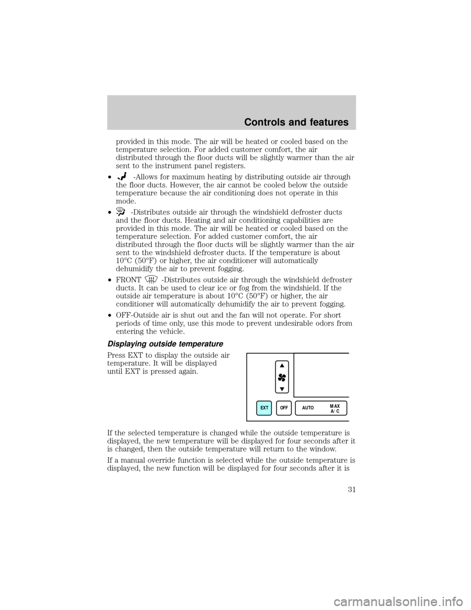
Press EXT to display the outside air
temperature. It will be displayed
until EXT is pressed again.
If the selected temperature is changed while the outside temperature is
displayed, the new temperature will be displayed for four seconds after it
is changed, then the outside temperature will return to the window.
If a manual override function is selected while the outside temperature is
displayed, the new function will be displayed for four seconds after it is
EXT OFF AUTOMAX
A/C
Controls and features
31
Page 53 of 176
and gates, and can also control home or office lighting and security
systems (with the available accessory package).
When programming your HomeLinktUniversal Transmitter, you
will be operating the garage door or gate. Be sure that people
and objects are out to the way to prevent potential harm or damage.
Do not use the HomeLinktUniversal Transmitter with any garage door
opener that lacks safety stop and reverse features as required by U.S.
federal safety standards (this includes any garage door opener model
manufactured before April 1, 1982). A garage door which cannot detect
an object, signaling the door to stop and reverse, does not meet current
U.S. federal safety standards. For more information on this matter, call
toll-free: 1±800±355±3515.
Programming
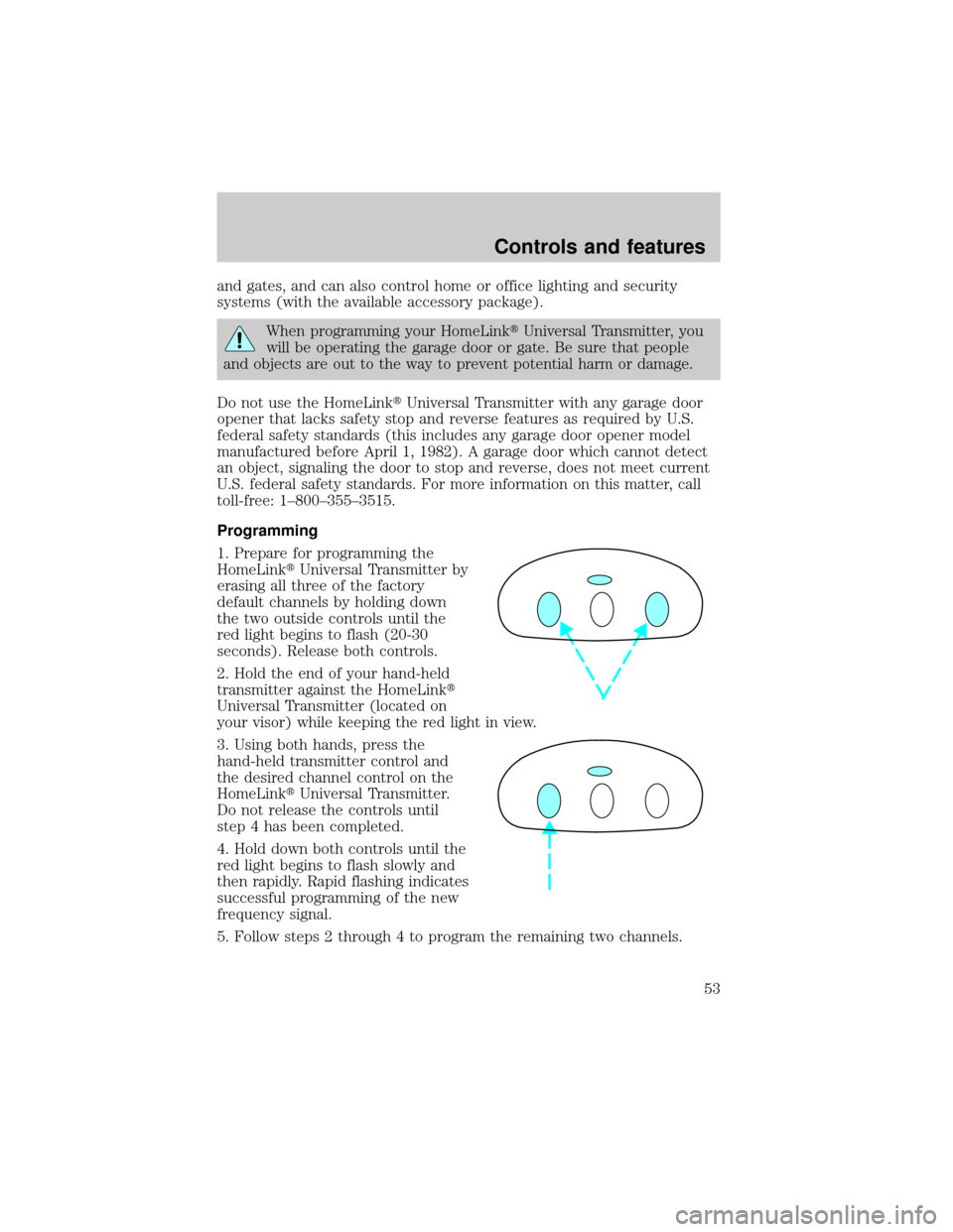
1. Prepare for programming the
HomeLinktUniversal Transmitter by
erasing all three of the factory
default channels by holding down
the two outside controls until the
red light begins to flash (20-30
seconds). Release both controls.
2. Hold the end of your hand-held
transmitter against the HomeLinkt
Universal Transmitter (located on
your visor) while keeping the red light in view.
3. Using both hands, press the
hand-held transmitter control and
the desired channel control on the
HomeLinktUniversal Transmitter.
Do not release the controls until
step 4 has been completed.
4. Hold down both controls until the
red light begins to flash slowly and
then rapidly. Rapid flashing indicates
successful programming of the new
frequency signal.
5. Follow steps 2 through 4 to program the remaining two channels.
Controls and features
53
Page 57 of 176
5. Release the switch, then slowly press it down again. Press the switch
repeatedly until the correct zone setting for your geographic location is
displayed on the upper right corner of the mirror.
6. To exit the zone setting mode, release pressure from the switch for
greater than two seconds.
Compass calibration adjustment
Perform this adjustment in an open area free from steel structures and
high voltage lines.
For optimum calibration, turn off all electrical accessories (heater/air
conditioning, wipers, etc.) and make sure all vehicle doors are shut.
1. Start the vehicle.
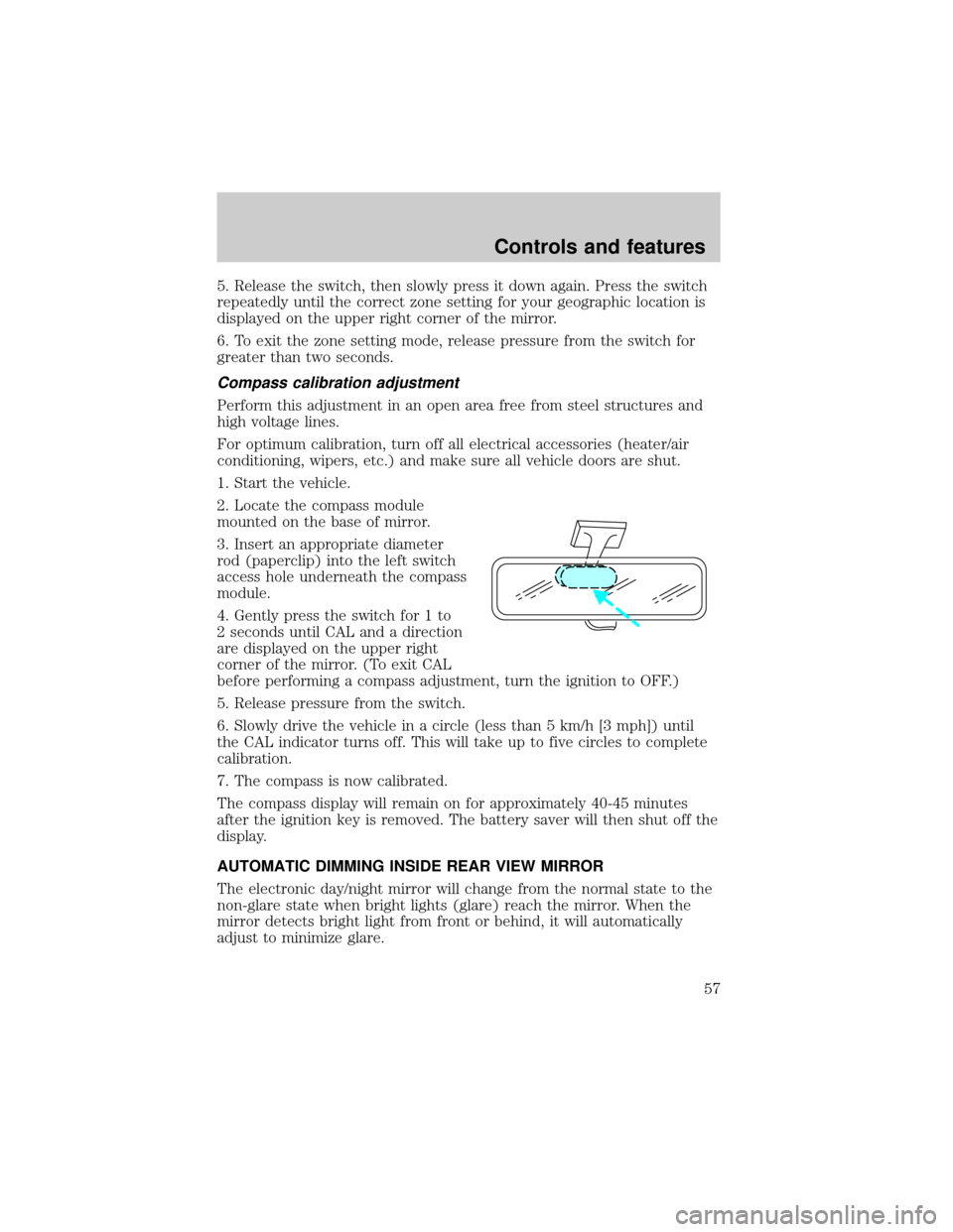
2. Locate the compass module
mounted on the base of mirror.
3. Insert an appropriate diameter
rod (paperclip) into the left switch
access hole underneath the compass
module.
4. Gently press the switch for 1 to
2 seconds until CAL and a direction
are displayed on the upper right
corner of the mirror. (To exit CAL
before performing a compass adjustment, turn the ignition to OFF.)
5. Release pressure from the switch.
6. Slowly drive the vehicle in a circle (less than 5 km/h [3 mph]) until
the CAL indicator turns off. This will take up to five circles to complete
calibration.
7. The compass is now calibrated.
The compass display will remain on for approximately 40-45 minutes
after the ignition key is removed. The battery saver will then shut off the
display.
AUTOMATIC DIMMING INSIDE REAR VIEW MIRROR
The electronic day/night mirror will change from the normal state to the
non-glare state when bright lights (glare) reach the mirror. When the
mirror detects bright light from front or behind, it will automatically
adjust to minimize glare.
Controls and features
57
Page 85 of 176
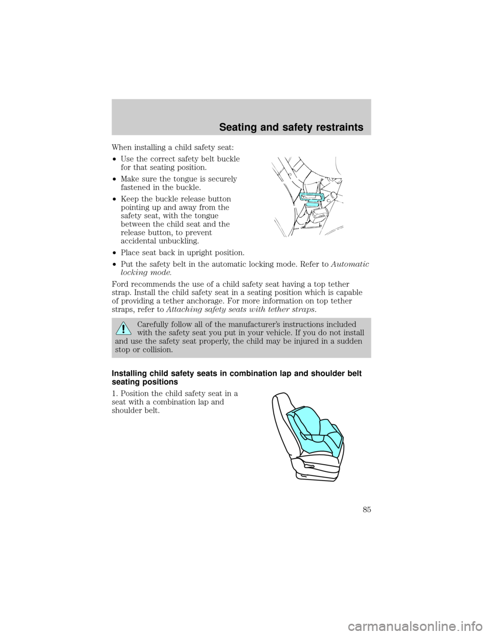
When installing a child safety seat:
²Use the correct safety belt buckle
for that seating position.
²Make sure the tongue is securely
fastened in the buckle.
²Keep the buckle release button
pointing up and away from the
safety seat, with the tongue
between the child seat and the
release button, to prevent
accidental unbuckling.
²Place seat back in upright position.
²Put the safety belt in the automatic locking mode. Refer toAutomatic
locking mode.
Ford recommends the use of a child safety seat having a top tether
strap. Install the child safety seat in a seating position which is capable
of providing a tether anchorage. For more information on top tether
straps, refer toAttaching safety seats with tether straps.
Carefully follow all of the manufacturer's instructions included
with the safety seat you put in your vehicle. If you do not install
and use the safety seat properly, the child may be injured in a sudden
stop or collision.
Installing child safety seats in combination lap and shoulder belt
seating positions
1. Position the child safety seat in a
seat with a combination lap and
shoulder belt.
Seating and safety restraints
85
Page 123 of 176
Connecting the jumper cables
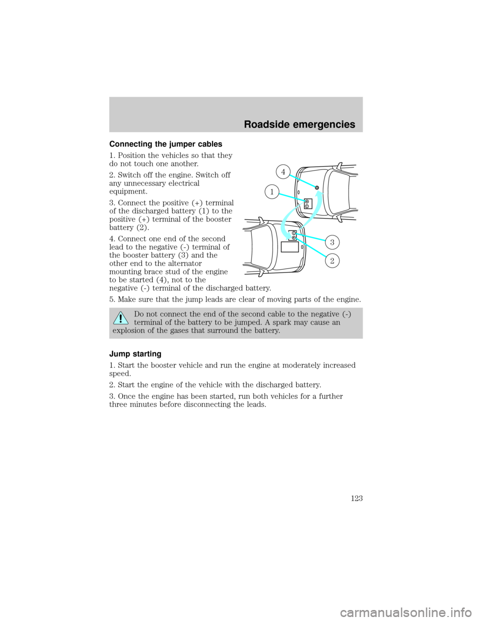
1. Position the vehicles so that they
do not touch one another.
2. Switch off the engine. Switch off
any unnecessary electrical
equipment.
3. Connect the positive (+) terminal
of the discharged battery (1) to the
positive (+) terminal of the booster
battery (2).
4. Connect one end of the second
lead to the negative (-) terminal of
the booster battery (3) and the
other end to the alternator
mounting brace stud of the engine
to be started (4), not to the
negative (-) terminal of the discharged battery.
5. Make sure that the jump leads are clear of moving parts of the engine.
Do not connect the end of the second cable to the negative (-)
terminal of the battery to be jumped. A spark may cause an
explosion of the gases that surround the battery.
Jump starting
1. Start the booster vehicle and run the engine at moderately increased
speed.
2. Start the engine of the vehicle with the discharged battery.
3. Once the engine has been started, run both vehicles for a further
three minutes before disconnecting the leads.
+–
+–
4
1
3
2
Roadside emergencies
123