Page 2239 of 2490
Instrument Panel and Console - Instrument Cluster Finish Panel
Removal and Installation
Removal
Installation
1.
Turn ignition key to position II.
2. Move steering column to lowest and fully extended position.
3. Turn ignition key to position 'O'.
4. Remove battery cover and disc onnect ground cable from
battery terminal. Refer to 86.15.15.
5. Release veneer panel from retaining clips.
6. Remove veneer panel from vehicle.
7. Remove and discard all retaining clips.
1. Fit new retaining clips to instrument surround.
2. Fit and fully seat veneer pa nel to instrument surround.
3. Connect ground cable to battery terminal and fit battery cover.
Refer to 86.15.15.
4. Turn ignition key to position II.
5. Return steering column to original position.
6. Turn ignition key to position 'O'.
Page 2240 of 2490
Instrument Panel and Console - Instrument Cluster Finish Panel Bezel
Removal and Installation
Removal
1. Adjust steering column to full y extended and lowered position.
2. Remove battery cover and disc onnect ground cable from
battery terminal. Refer to 86.15.19.
3. Remove veneer from instrument panel. Refer to 76.47.24.
4. Using a small screwdriver, de press fog lamp switch upper
retaining tang and release sw itch from gauge surround.
5. Position fog lamp switch fo r access, disconnect harness
multiplug and remove switch.
6. Using a small screwdriver, depress trip keyboard upper
retaining tang and release ke yboard from gauge surround.
7. Position trip keyboard for ac cess and disconnect harness
multiplug.
Page 2241 of 2490
Installation
8. Slacken and remove four screws securing major gauge
module/surround to fascia and withdraw surround.
1. Position major gauge surround on panel, routing harness
multiplugs through apertures.
2. Fit and tighten screws securing major gauge module/surround
to fascia.
3. Connect harness multiplug to tr ip keyboard and fit and fully
seat keyboard in gauge surround, ensuring correct location of
retaining tangs
4. Connect harness multiplug to fog lamp switch and fit and fully
seat switch in gaug e surround, ensuring correct location of
tangs.
5. Fit veneer panel. Refer to 76.47.24.
6. Connect ground cable to battery terminal and fit battery cover.
Refer to 86.15.15.
7. Return steering column to original position.
Page 2242 of 2490

Instrument Panel and Console - Instrument Panel
Removal and Installation
Removal
1. Turn ignition switch to position II.
2. Motor driver and front passenger seats rearward.
3. Position steering wheel in stra ight ahead position and fully
lower and extend steering column.
4. Turn ignition switch to position O.
5. Remove battery cover and disc onnect ground cable from
battery terminal. Refer to 86.15.19.
6. Remove 'J' gate finish er. Refer to 76.25.24.
7. Remove 'J' gate finisher retain ing panel. Refer to 76.25.26.
8. Remove centre console veneer panel. Refer to 76.47.26.
9. Disconnect and remove radio.
10. Remove centre console switch module. Refer to 86.80.32.
11. Remove centre console. Refer to 76.25.01.
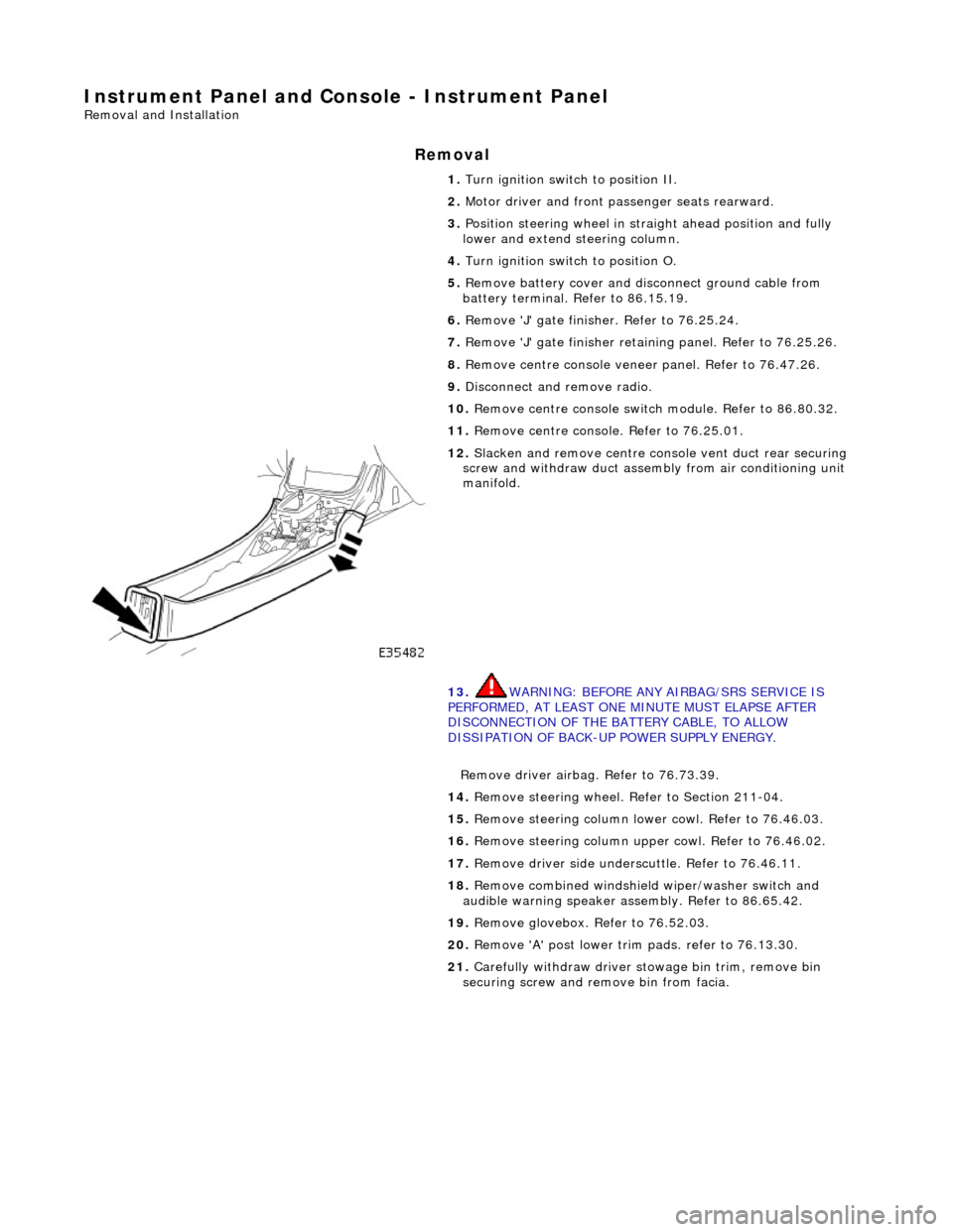
12. Slacken and remove centre cons ole vent duct rear securing
screw and withdraw duct assemb ly from air conditioning unit
manifold.
13. WARNING: BEFORE ANY AIRBAG/SRS SERVICE IS
PERFORMED, AT LEAST ONE MINUTE MUST ELAPSE AFTER
DISCONNECTION OF THE BATTERY CABLE, TO ALLOW
DISSIPATION OF BACK-UP POWER SUPPLY ENERGY.
Remove driver airbag. Refer to 76.73.39.
14. Remove steering wheel. Refer to Section 211-04.
15. Remove steering column lo wer cowl. Refer to 76.46.03.
16. Remove steering column u pper cowl. Refer to 76.46.02.
17. Remove driver side unders cuttle. Refer to 76.46.11.
18. Remove combined windshield wiper/washer switch and
audible warning speaker assembly. Refer to 86.65.42.
19. Remove glovebox. Refer to 76.52.03.
20. Remove 'A' post lower trim pads. refer to 76.13.30.
21. Carefully withdraw driver stowage bin trim, remove bin
securing screw and remove bin from facia.
Page 2243 of 2490
22. Accessing via driver stowage bin aperture, disconnect facia
harness to centre console harness multiplugs.
23. Release driver side facia harness to passenger compartment
harness multiplug retaining le ver and disconnect multiplug.
24. From RH side footwell, remove nut securing facia harness
ground eyelet to tunnel front stud and disconnect eyelet from
stud.
25. Remove steering column reac h adjustment motor harness
multiplug (yellow) from retain ing bracket and disconnect
multiplug.
Page 2244 of 2490
26. Remove steering column tilt adjustme nt motor harness
multiplug from retaining bracke t and disconnect multiplug.
27. Remove bolt securing facia moun ting bracket to RH side of
tunnel.
28. Remove facia RH end aperture trim pad.
29. CAUTION: The 'A' post facia mounting brackets are pre-
set to the body and must no t under any circumstances be
disturbed.
Remove two bolts securing facia to RH 'A' post mounting
bracket.
Page 2262 of 2490
54. Install radio. Refer to 86.50.03.
55. Install facia centre veneer panel. Refer to 76.47.06.
56. Install centre console veneer panel. Refer to 76.47.26.
57. Install 'J' gate finisher retain ing panel. Refer to 76.25.26.
58. Install 'J' gate surround. Refe r to 76.25.24, Section 307-05A
(N/A), 307-05B (S/C).
59. Connect steering column tilt motor harness multiplug and
install multiplug on retaining bracket.
60. Connect steering column reac h motor harness multiplug and
install multiplug on retaining bracket.
61. Position ground cable eyelet on RH 'A' post stud and install
securing nut.
62. Connect driver side facia harn ess to passenger compartment
harness multiplug and secure with retaining lever.
63. Connect driver side facia harness to console harness
multiplugs.
Page 2263 of 2490
64.
Position driver stowage bin in facia, install securing screw and fully seat trim.
65. Install trim pad on driver si de lower 'A' post. Refer to
76.13.30.
66. Install driver side unders cuttle. Refer to 76.46.11.
67. Install combined windshield wi per/washer switch and audible
warning speaker assembly. Refer to 86.65.42.
68. Install steering column upper cowl. Refer to 76.46.02.
69. Install steering column lower cowl. Refer to 76.46.03.
70. Install steering wheel. Refer to 211-04.
71. Install driver side airbag. Refer to 76.73.39.