Page 593 of 2490
Engine - Cr
ankshaft
Pulley4.0L NA V8 - AJ 27/3.2L NA V8 - AJ26
In-v
ehicle Repair
Remov
al
S
pecial Tool(s)
Cr
ankshaft locking, main tool
303-191
Adaptor
303-191-02
Crankshaft front
seal remover
303-541
Crankshaft front seal replacer
3
03-542
Crankshaft pull
ey/damper remover
303-588
1. Open the engine compartment and fit paintwork protection
sheets.
2. Set the engine compartment cover to the service access
position.
3. Remove the drive belt from the fro nt accessory drive. Refer to
Operation 12.10.40.
4. Remove the twin fan and motor assembly for access. Refer to
Operation 26.25.12
5. CAUTION: Under no circumstan ces should the crankshaft
setting peg 303-531 be used in the following operations, to lock
the crankshaft.
• NOTE: Should extra locking of the crankshaft be required, use a
lever against one torque converte r boss. Remove the plastic mesh
cover from the torque converter housing for access.
Page 597 of 2490
C
rankshaft Pulley Vehicles With: Supercharger 12.21.09
Special Service tools
C
rankshaft locking, main tool
303-191
A
daptor
303-191-02
A
daptor
303-191-03
Page 598 of 2490
Cr
ankshaft front seal remover
303-541
Cr
ankshaft front seal replacer
303-542
Cr
ankshaft pulley/damper remover
303-588
Removal
1. Open the engine compartment and fit paintwork protection sheets.
2. Set the engine compartment cover to the service access position.
3. Remove the supercharger drive belt. Refer to Operation <<18.50.08>>.
4. Remove the drive belt from the front accessory drive. Refer to Operation <<12.10.40>>.
Page 611 of 2490

E
ngine - Cylinder Head LH
In-ve
hicle Repair
Remova
l
CAU
TION: If a replacement cylinder head is to be installed to a
vehicle with variable camshaft timing (VCT) the cylinder head m ust have the
oil gallery blind rivet removed before installation.
Spe
cial Tool(s)
Cams
haft setting
303-530
Ti
ming chain tensioning
303-532
Wedges, prim
ary chain
303-533
Cr
ankshaft setting
303-531
1.
Open the engine compartment and install paintwork protection sheets.
2. Set the engine compartment cover to the service access position.
3.
Disconnect the battery ground cable.
Re
move the battery cover.
4. Remove the engine fron cover.For additional information, refer to: Engine
Front Cover (303-01 Engi
ne, In-vehicle Repair).
5. Remove the Inlet Manifold. Refer to Operation 30.15.01 in this Section. This operation includes depressurising the fuel system and removing the throttle
housing.
6. Disconnect the hoses and multi-plug from the coolant outlet pipe.
1. Release and reposition the hose clip, and disconnect the heater hose.
2. Disconnect the multi-plug from the temperature sensor.
3. Release and reposition the hose clip along the bypass hose.
Page 626 of 2490
46
. Mov
e the engine compartment cover from the service position and connect
the gas struts.
47. Remove the paint protection sheets and close the cover.
48. Connect the battery and install the battery cover.
Refe
r to the Battery Reconne
ction Procedure 86.15.15.
Page 627 of 2490

E
ngine - Cylinder Head RH
In-ve
hicle Repair
Remova
l
CAU
TION: If a replacement cylinder head is to be installed to a
vehicle with variable camshaft timing (VCT) the cylinder head m ust have the
oil gallery blind rivet removed before installation.
Spe
cial Tool(s)
Cams
haft setting
303-530
Ti
ming chain tensioning
303-532
Wedges, prim
ary chain
303-533
Cr
ankshaft setting
303-531
1.
Open the engine compartment and install paintwork protection sheets.
2. Set the engine compartment cover to the service access position.
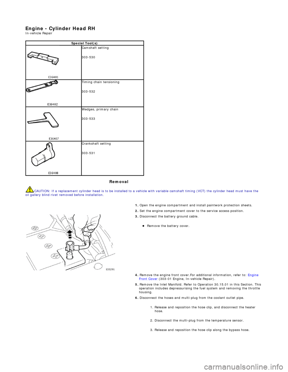
3.
Disconnect the battery ground cable.
Re
move the battery cover.
4. Remove the engine front cover.For additional information, refer to: Engine
Front Cover (303-01 Engi
ne, In-vehicle Repair).
5. Remove the Inlet Manifold. Refer to Operation 30.15.01 in this Section. This operation includes depressurising the fuel system and removing the throttle
housing.
6. Disconnect the hoses and multi-plug from the coolant outlet pipe.
1. Release and reposition the hose clip, and disconnect the heater hose.
2. Disconnect the multi-plug from the temperature sensor.
3. Release and reposition the hose clip along the bypass hose.
Page 641 of 2490
2.
Connect the multi-plug to the temperature sensor.
3. Expand and reposition the hose clip along the bypass hose.
43. Install the Inlet Manifold. Refer to Operation 30.15.01 in this Section. This
operation includes installing the throttle housing.
44. Install the engine front cover.For additional information, refer to: Engine
Front Cover (303-01 Engi
ne, In-vehicle Repair).
45. Move the engine compartment cover from the service position and connect
the gas struts.
46. Remove the paint protection sheets and close the cover.
47. Connect the battery and install th e battery cover.For additional
information, refer to: Battery Connect
(414
-01 Battery, Mounting and
Cables, General Procedures).
Page 642 of 2490
Engine - Engine Front Cover
In-vehic
le Repair
Remov
a
l
1.
Op
en the engine compartment and fit paintwork protection
sheets.
2. Set the bonnet to the service access position.
3. Disc
onnect the batt
ery ground cable.
Re
move the battery cover.
4. Drain the coolant from the radiator. Refer to Operation
26.10.01.
5. Disc onne
ct the radiator top hose.
1. Slacken the hose retaining clip and reposition the clip
along the hose.
2. Disconnect the hose from the radiator.
6. Disc
onnect the top hose from the coolant outlet pipe.
1. Release and reposition th e hose clip, and disconnect
the top hose.
7. Slacken the three screws which secure the water pump pulley.