Page 2079 of 2490
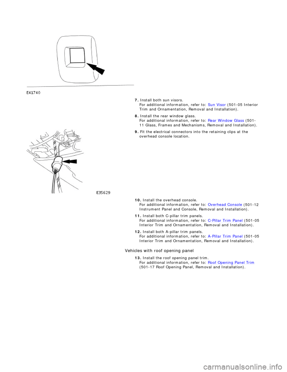
Vehicles with roof opening panel
7. Install both sun visors.
For additional information, refer to: Sun Visor (501-05 Interior
Trim and Ornamentation, Re moval and Installation).
8. Install the rear window glass.
For additional information, refer to: Rear Window Glass
(501-
11 Glass, Frames and Mechanis ms, Removal and Installation).
9. Fit the electrical connectors into the retaining clips at the
overhead console location.
10. Install the overhead console.
For additional information, refer to: Overhead Console
(501-12
Instrument Panel and Console, Removal and Installation).
11. Install both C-pillar trim panels.
For additional information, refer to: C
-Pillar Trim Panel (501-05
Interior Trim and Ornamentatio n, Removal and Installation).
12. Install both A-pillar trim panels.
For additional information, refer to: A
-Pillar Trim Panel (501-05
Interior Trim and Ornamentatio n, Removal and Installation).
13. Install the roof opening panel trim.
For additional information, refer to: Roof Opening Panel Trim
(501-17 Roof Opening Panel, Removal and Installation).
Page 2212 of 2490
Glass, Frames and Mechanisms - Windshield Glass
Removal and Installation
Removal
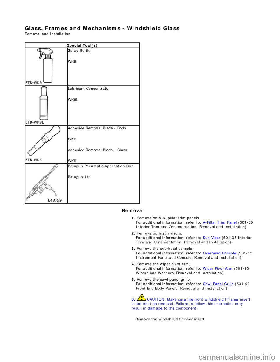
Special Tool(s)
Spray Bottle
WK9
Lubricant Concentrate
WK9L
Adhesive Removal Blade - Body
WK6
Adhesive Removal Blade - Glass
WK5
Betagun Pneumatic Application Gun
Betagun 111
1. Remove both A- pill ar trim panels.
For additional information, refer to: A
-Pillar Trim Panel (501-05
Interior Trim and Ornamentatio n, Removal and Installation).
2. Remove both sun visors.
For additional information, refer to: Sun Visor
(501-05 Interior
Trim and Ornamentation, Re moval and Installation).
3. Remove the overhead console.
For additional information, refer to: Overhead Console
(501-12
Instrument Panel and Console, Removal and Installation).
4. Remove the wiper pivot arm.
For additional information, refer to: Wiper Pivot Arm
(501-16
Wipers and Washers, Remo val and Installation).
5. Remove the cowl panel grille.
For additional information, refer to: Cowl Panel Grille
(501-02
Front End Body Panels, Removal and Installation).
6. CAUTION: Make sure the front windshield finisher insert
is not bent on removal. Failure to follow this instruction may
result in damage to the component.
Remove the windshield finisher insert.
Page 2214 of 2490
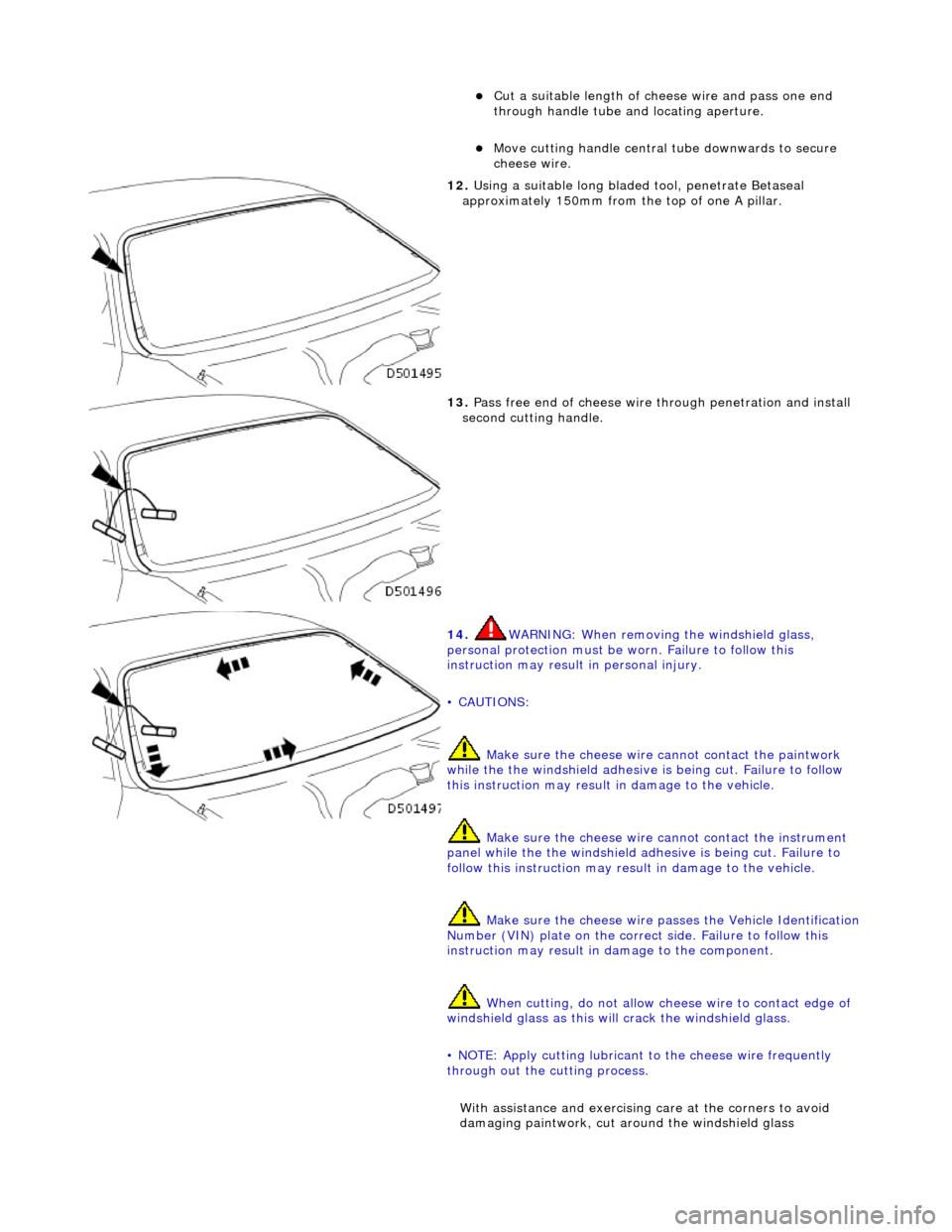
Cut a suitable length of cheese wire and pass one end
through handle tube and locating aperture.
Move cutting handle central tube downwards to secure
cheese wire.
12. Using a suitable long bladed tool, penetrate Betaseal
approximately 150mm from the top of one A pillar.
13. Pass free end of cheese wire through penetration and install
second cutting handle.
14. WARNING: When removing the windshield glass,
personal protection must be worn. Failure to follow this
instruction may result in personal injury.
• CAUTIONS:
Make sure the ch eese wire cannot contact the paintwork
while the the windshield adhesive is being cut. Failure to follow
this instruction may result in damage to the vehicle.
Make sure the cheese wire cannot contact the instrument
panel while the the windshield adhesive is being cut. Failure to
follow this instruction may result in damage to the vehicle.
Make sure the cheese wire passes the Vehicle Identification
Number (VIN) plate on the correct side. Failure to follow this
instruction may result in damage to the component.
When cutting, do not allow ch eese wire to contact edge of
windshield glass as this will crack the windshield glass.
• NOTE: Apply cutting lubricant to the cheese wire frequently
through out the cutting process.
With assistance and exercising care at the corners to avoid
damaging paintwork, cut around the windshield glass
Page 2218 of 2490
15. Remove protective tape from leading edge of headlining.
16. Remove the protective sheet and the protective board from
the fascia.
17. Install the overhead console.
For additional information, refer to: Overhead Console
(501-12
Instrument Panel and Console, Removal and Installation).
18. Install both sun visors.
For additional information, refer to: Sun Visor
(501-05 Interior
Trim and Ornamentation, Re moval and Installation).
19. Install both A-pillar trim panels.
For additional information, refer to: A
-Pillar Trim Panel (501-05
Interior Trim and Ornamentatio n, Removal and Installation).
Page 2219 of 2490
Instrument Panel and Console - Instrument Panel and Instrument Panel
Console
Description and Operation
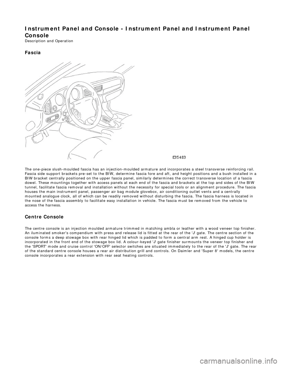
Fascia
The one-piece slush-moulded fascia has an injection-moulded ar mature and incorporates a steel transverse reinforcing rail.
Fascia side support brackets pre-set to th e BIW, determine fascia fore and aft, and height position s and a bush installed in a
BIW bracket centrally positioned on the upper fascia panel, similarly determines the correct transverse location of a fascia
dowel. These mountings together with access panels at each en d of the fascia and brackets at the top and sides of the BIW
tunnel, facilitate fascia removal and instal lation without the necessity for special tools or an alignment procedure. The fasci a
houses the main instrument panel, pass enger air bag module glovebox, air conditioning outlet vents and a centrally
mounted analogue clock, all of which can be readily removed wi thout disturbing the fascia. The fascia harness is located in
the nose of the fascia assembly to facilitate easy installati on in vehicle. The fascia must be removed from the vehicle to
access the harness.
Centre Console
The centre console is an injection moulded armature trimmed in matching ambla or leather with a wood veneer top finisher.
An iluminated smoker's compendium with pr ess and release lid is fitted at the rear of the 'J' gate. The centre section of the
console forms a deep stowage box with rear hinged lid which is padded to form a central arm rest. A hinged cup holder is
incorporated in the front end of the stowage box lid. A colour-keyed 'J' gate finisher surmounts the veneer top finisher and
the 'SPORT' mode and cruise control 'ON/OFF' selector switches are situated immediately to the rear of the 'J' gate. The rear
of the standard centre console houses a re ar air distribution grill and controls. On Daimler and 'Super 8' models, the centre
console incorporates a rear extensio n with rear seat heating controls.
Page 2220 of 2490
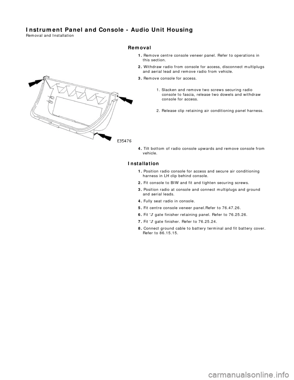
Instrument Panel and Console - Audio Unit Housing
Removal and Installation
Removal
Installation
1.
Remove centre console veneer pa nel. Refer to operations in
this section.
2. Withdraw radio from console for access, disconnect multiplugs
and aerial lead and remo ve radio from vehicle.
3. Remove console for access.
1. Slacken and remove tw o screws securing radio
console to fascia, release two dowels and withdraw
console for access.
2. Release clip retaining air conditioning panel harness.
4. Tilt bottom of radio console upwards and remove console from
vehicle.
1. Position radio console for access and secure air conditioning
harness in LH clip behind console.
2. Fit console to BIW and fit an d tighten securing screws.
3. Position radio at console and connect multiplugs and ground
and aerial leads.
4. Fully seat radio in console.
5. Fit centre console veneer panel.Refer to 76.47.26.
6. Fit 'J' gate finisher retain ing panel. Refer to 76.25.26.
7. Fit 'J' gate finisher . Refer to 76.25.24.
8. Connect ground cable to battery terminal and fit battery cover.
Refer to 86.15.15.
Page 2221 of 2490
Instrument Panel and Console - Climate Control Assembly Housing
Removal and Installation
Removal
Installation
1. Move 'J' gate selector to position 'D.'
2. Remove battery cover and disc onnect ground cable from
battery terminal. Refer to 86.15.19.
3. Remove 'J' gate finish er. Refer to 76.25.24.
4. Remove 'J' gate finisher reta ining plate.Refer to 76.25.26.
5. Remove centre console veneer panel. Refer to 76.47.26.
6. Remove radio and console. Refer to operations in this section.
7. Disconnect air conditioning panel flying lead multiplug (blue)
in LH side of transmission tunnel.
8. Slacken and remove remaining screw securing air
conditioning panel console to BIW.
9. Withdraw air conditioning panel and console for access and
disconnect the harness multiplug behind panel.
10. Remove air conditioning panel from vehicle.
11. Remove panel from console.
1. Fit air conditioning panel to console.
Page 2223 of 2490
Instrument Panel and Console - Coin Stowage Compartment
Removal and Installation
Removal
Installation
1.
Slacken and remove screw securing driver stowage
compartment to fascia.
2. Withdraw stowage compartment from fascia and remove from
vehicle.
1. Position driver stowage compartment in fascia recess.
2. Install stowage compartment to fascia securing screw.