Page 75 of 2490

I
nstallation
23
.
Install special tool 204-200 on ball joint and operate press to
release joint from wishbone.
24. Remove special tool from ball joint.
25. Remove ball joint and wishbone from press.
26. Ensuring that their relative positions are clearly marked,
place ball joint, rubber gaiter and retaining clip in a clean
plastic bag and return for warranty purposes.
27. Thoroughly clean wishbone paying particular attention to ball
joint and pivot bolt locations.
1. Inst
all ball joint in wishbone.
Pos
ition support of special tool 204-199 on press bed and
place wishbone on tool.
U
sing ball joint plastic cover to align, position mandrel of
special tool 204-199 on ball joint
Ali
gn assembly with press ram and operate press to fully
seat ball joint in wishbone.
2. Remove tool mandrel 204-199 from ball joint.
3. Remove wishbone and support tool 204-199 from press.
4. Position wishbone on suspensi on beam, install fulcrum shaft
thread rearward, install nu t and tighten to 60-80Nm.
Page 87 of 2490
12
.
Install nut securing upper ball jo int to vertical link and tighten
to 60-80Nm.
13
.
Position tie rod ball joint taper pin on steering arm and install
and tighten nut to 71-85Nm.
14. Raise vehicle and support on st ands to provide access for
Special Tool 204-111 and road spring.
15
.
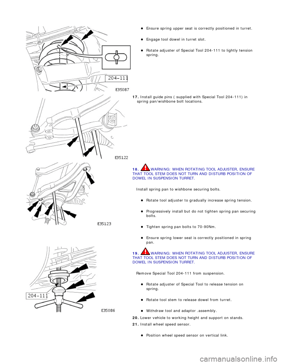
Install spring pan, rubber lowe r seat, spring and rubber upper
seat on Special Tool 204-111.
16. Install road spring in suspension turret.
Install
spring pan/spring as
sembly and Special Tool 204-
111 in suspension turret.
Page 88 of 2490

Ensure spring
upper se
at is correctly positioned in turret.
Engage tool dowel in turret slo
t.
R
o
tate adjuster of Special Tool 204-111 to lightly tension
spring.
17 . Ins
tall guide pins ( supplied with Special Tool 204-111) in
spring pan/wishbone bolt locations.
18 . WARNING: WHE
N ROTATING TOOL ADJUSTER, ENSURE
THAT TOOL STEM DOES NOT TU RN AND DISTURB POSITION OF
DOWEL IN SUSPENSION TURRET.
Install spring pan to wishbone securing bolts.
Ro t
ate tool adjuster to gradua
lly increase spring tension.
Pr
ogressively install but do no
t tighten spring pan securing
bolts.
Tigh ten spring pan
bolts to 70-90Nm.
Ensure spri
ng
lower seat is co
rrectly positioned in spring
pan.
19 . WARNING: WHE
N ROTATING TOOL ADJUSTER, ENSURE
THAT TOOL STEM DOES NOT TU RN AND DISTURB POSITION OF
DOWEL IN SUSPENSION TURRET.
Remove Special Tool 204-111 from suspension.
Rotat
e adjuster of Special Tool to release tension on
spring.
R otate
tool stem to release dowel from turret.
With
draw tool and adaptor
.assembly.
20
. Lower vehi
cle to working heig
ht and support on stands.
21. Install wheel speed sensor.
Positi
on wheel speed sensor on vertical link.
Page 101 of 2490
16
.
Install spring pan, rubber lowe r seat, spring and rubber upper
seat on Special Tool 204-111.
17
.
Install spring pan/spring asse mbly and special tool 204-111
in suspension turret.
E
nsuring upper seat is correctly positioned, install spring
in suspension turret.
Engage tool
dowel in turret slot.
18
.
Rotate tool adjuster to lightly tension spring.
19. Install suitable guide pins in spring pan/wishbone bolt
locations.
Page 102 of 2490

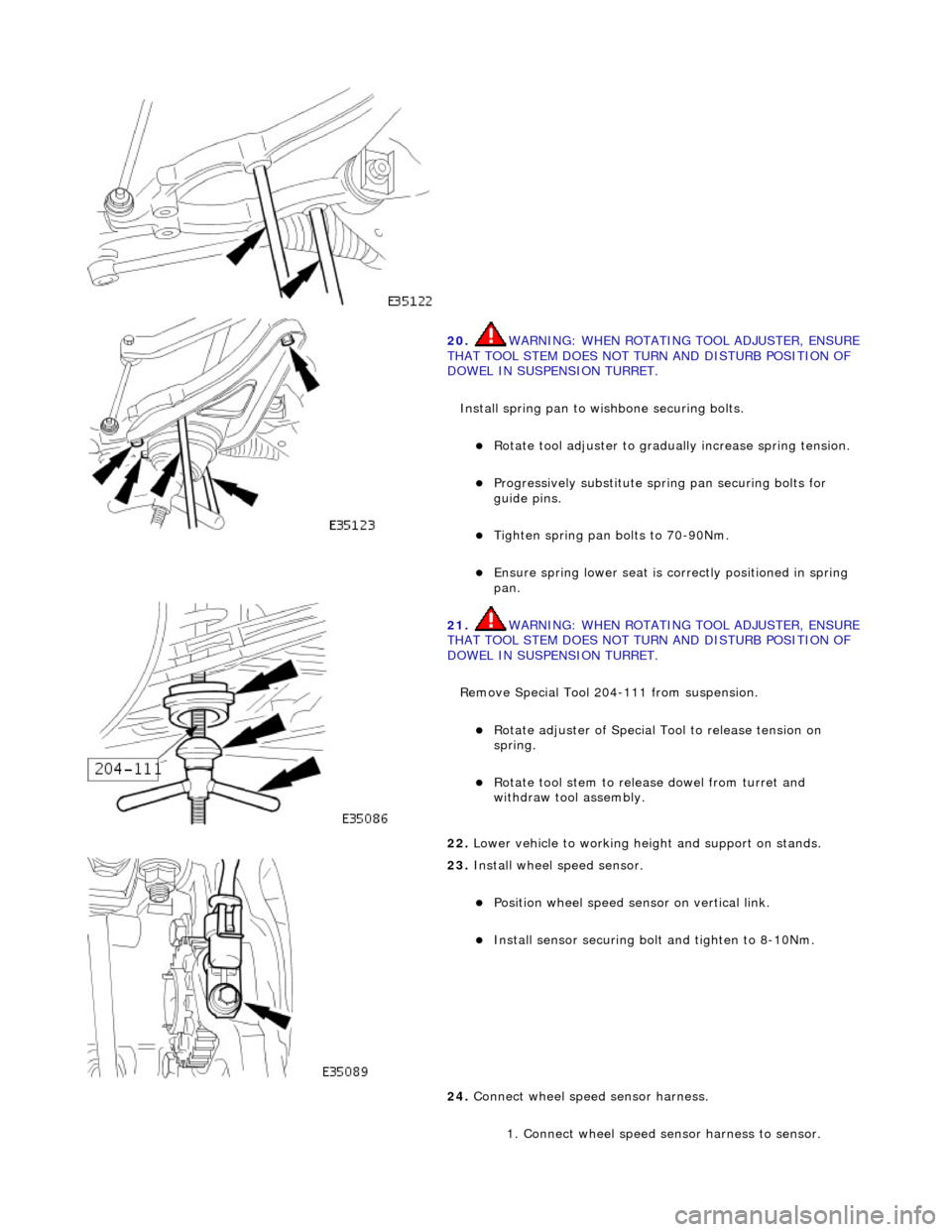
20. WARNING: WHE
N ROTATING TOOL ADJUSTER, ENSURE
THAT TOOL STEM DOES NOT TU RN AND DISTURB POSITION OF
DOWEL IN SUSPENSION TURRET.
Install spring pan to wishbone securing bolts.
Ro t
ate tool adjuster to gradua
lly increase spring tension.
Pr
ogressively substitute spri
ng pan securing bolts for
guide pins.
Tighten spring pan
bolts to 70-90Nm.
Ensure spri
ng
lower seat is co
rrectly positioned in spring
pan.
21 . WARNING: WHE
N ROTATING TOOL ADJUSTER, ENSURE
THAT TOOL STEM DOES NOT TU RN AND DISTURB POSITION OF
DOWEL IN SUSPENSION TURRET.
Remove Special Tool 204-111 from suspension.
Rotat
e adjuster of Special Tool to release tension on
spring.
R o
tate tool stem to release dowel from turret and
withdraw tool assembly.
22 . Lower vehi
cle to working heig
ht and support on stands.
23 . Inst
all wheel speed sensor.
Posi
ti
on wheel speed sensor on vertical link.
Instal
l sensor securing bolt
and tighten to 8-10Nm.
24. Connect wheel speed sensor harness.
1. Connect wheel speed sensor harness to sensor.
Page 110 of 2490
In
stallation
5.
WA
RNING: WHEN TURNING TOOL ADJUSTER, ENSURE
THAT TOOL STEM DOES NOT ROTATE AND DISTURB POSITION
OF DOWEL IN SUSPENSION TURRET.
Rotate adjuster of Special Tool to tension spring.
6. Re
move spring pan to lower
wishbone securing bolts.
7. WA
RNING: WHEN TURNING TOOL ADJUSTER, ENSURE
THAT TOOL STEM DOES NOT ROTATE AND DISTURB POSITION
OF DOWEL IN SUSPENSION TURRET.
Rotate adjuster of Special Tool to release tension from spring.
8. Re
move spring assembly and Special Tool from suspension
turret.
9. Remove Special Tool from spring assembly.
1. Install spring pan, new spring and new spring rubber upper
and lower seats on Special Tool 204-111.
Page 111 of 2490
2. Ins
tall Special Tool 204-111 and spring assembly in suspension
turret.
P
osition spring assembly and Special Tool in suspension
turret.
Ensure spri
ng upper rubber se
at is correctly positioned
and fully seated.
Engage tool
dowel in turret slot.
3. Position spr
ing pan on lower wishbone.
Ro
tate adjuster of Special Tool to lightly tension spring.
Al
ign spring pan with lower wishbone bolt locations.
4. Inst
all suitable guide pins in
spring pan/wishbone bolt
locations.
5. WARNING: WHEN ROTATING TOOL ADJUSTER, ENSURE
THAT TOOL STEM DOES NOT TU RN AND DISTURB POSITION OF
DOWEL IN SUSPENSION TURRET.
Install spring pan to wishbone securing bolts.
Page 112 of 2490
Rot
ate tool adjuster to gradua
lly increase spring tension.
Pr
ogressively substitute spri
ng pan securing bolts for
guide pins.
Ti ghten spring pan
securing bolts to 70-90Nm.
6. WARNING: WHE N
ROTATING TOOL ADJUSTER, ENSURE
THAT TOOL STEM DOES NOT TU RN AND DISTURB POSITION OF
DOWEL IN SUSPENSION TURRET.
Remove Special Tool 204-111 from suspension.
Ensure spri ng
lower rubber seat
is correctly positioned and
fully seated.
R otat
e adjuster of Special Tool to release tension on
spring.
7. Ro
tate tool stem to release
dowel from turret and withdraw
tool assembly.
8. Lower vehicle to working heig ht and support on stands.
9. Install road wheel. Re fer to Section 100-02.
10. Raise vehicle, remove stands and lower vehicle onto road
wheels.