Page 1040 of 2490

Fuel Char
ging and Controls - Fu
el Injectors4.0L SC V8 - AJ26
Remo
val and Installation
Remov
a
l
Installation
1. Disc onne
ct battery ground cable (IMPORTANT, see SRO
86.15.19 for further information).
2. WARNING: BEFORE PROCEEDING, IT IS ESSENTIAL THAT
THE WARNING NOTES GIVEN IN SECTION 100-00 (UNDER THE
HEADING 'SAFETY PRECAUTIONS') ARE READ AND
UNDERSTOOD.
Depressurize fuel syst em; refer to 19.50.02.
3. Drain radiator coolant; refer to 2
6.10.01.
4. Remove air cleaner cover / inta ke assembly; refer 19.10.30.
5. Remove throttle body; refer to 19.70.04.
6. Remove throttle induction elbo w; refer to (SC) 19.70.28.
7. Remove exhaust gas re-circulation valve (EGR) if fitted; refer
to 17.45.01.
8. Remove supercharger outlet duct and gasket; refer to
18.50.16.
9. Remove coolant outlet pipe; refer to (SC) 26.31.08 .
10. Remove supercharger drive belt; refer to 18.50.08.
11. Remove supercharger assembly; refer to 18.50.15.
12. Remove bank 1 or 2 charge air cooler as required; refer to
18.50.18 and / or 18.50.19.
13 . Di
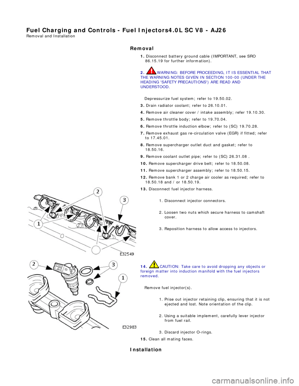
sconnect fuel injector harness.
1. Disconnect injector connectors.
2. Loosen two nuts which se cure harness to camshaft
cover.
3. Reposition harness to al low access to injectors.
14. CAUTI
ON: Take care to avoi
d dropping any objects or
foreign matter into induction ma nifold with the fuel injectors
removed.
Remove fuel injector(s). 1. Prise out injector retaining clip, ensuring that it is not
ejected and lost. Note orientation of the clip.
2. Using a suitable implemen t, carefully lever injector
from fuel rail.
3. Discard injector O-rings.
15 . Cle
an all mating faces.
Page 1041 of 2490

1.
Install
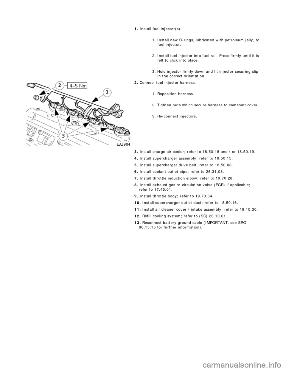
fuel injector(s).
1. Install new O-rings, lubricated with petroleum jelly, to
fuel injector.
2. Install fuel in jector into fuel rail. Press firmly until it is
felt to click into place.
3. Hold injector firmly down and fit injector securing clip
in the correct orientation.
2. Conne
ct fuel injector harness.
1. Reposition harness.
2. Tighten nuts which secure harness to camshaft cover.
3. Re-connect injectors.
3. Install charge air c ooler; refer to 18.50.18 and / or 18.50.19.
4. Install supercharger asse mbly; refer to 18.50.15.
5. Install supercharger driv e belt; refer to 18.50.08.
6. Install coolant outlet pi pe; refer to 26.31.08.
7. Install throttle induction elbow; refer to 19.70.28.
8. Install exhaust gas re-circulation valve (EGR) if applicable;
refer to 17.45.01.
9. Install throttle body ; refer to 19.70.04.
10. Install supercharger outlet duct; refer to 18.50.16.
11. Install air cleaner cover / intake assembly; re fer to 19.10.30.
12. Refill cooling system; refer to (SC) 26.10.01 .
13. Reconnect battery ground cable (IMPORTANT, see SRO
86.15.15 for further information).
Page 1043 of 2490
the
abutment bracket.
6. R
emove coolant hoses.
Inst
all suitable blanking plugs.
7. Re
lease connector from bracket
under LH side of assembly.
8. R
emove throttle body to indu
ction elbow securing bolts.
9. Remove throttle body from induction elbow.
1. Remove throttle body.
2. Discard gasket.
Cle
an mating faces.
Page 1045 of 2490
4. Inst
all coolant hoses.
5. R
eposition outer cable
to abutment bracket.
Install but do not tigh
ten adjusting nut.
6. CAUTI
ON: Under no circumst
ances should quadrant be
held clear of throttle stop by cable tension.
• NOTE: Make sure ther e is neither tension nor slack in the cable.
Install throttle cable.
Tigh
ten locknut without altering setting or introducing
twist into the cable outer.
7. Connect conn
ectors and vacuum pipe.
Page 1047 of 2490
14
.
Adjust kickdown switch to th e value as defined in step 8
(Installation).
15. Reconnect kickdown flying lead connector and verify setting.
16. Install air cleaner cover / intake assembly; refer 19.10.30.
17. Check coolant level and top up if required.
18. Reconnect battery ground cable (IMPORTANT, see SRO
86.15.15 for further information).
Page 1049 of 2490

Accessory Drive - Accessory Drive
Description an
d Operation
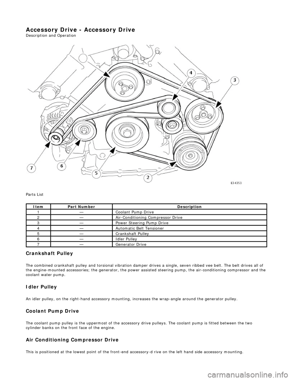
Parts List
Cran
kshaft Pulley
The combined crankshaft
pulley and torsio
nal vibration damper drives a single, seve n ribbed vee belt. The belt drives all of
the engine-mounted accessories; the generator, the power assi sted steering pump, the air-conditioning compressor and the
coolant water pump.
I
dler Pulley
An i
dler pulley, on the right-hand
accessory mounting, increases the wrap-angle around the generator pulley.
Coolant Pump Drive
The coolan
t pump pulley is the
uppermost of the accessory drive pulleys. Th e coolant pump is fitted between the two
cylinder banks on the front face of the engine.
Air Conditioning Compressor Drive
Thi
s is positioned at the lowest poin
t of the front-end accessory-d rive on the left hand side accessory mounting.
It
em
Par
t Number
De
scription
1—Coo
lant Pump Drive
2—Ai
r-Conditioning Compressor Drive
3—Power Steer
ing Pump Drive
4—Au
tomatic Belt Tensioner
5—Crankshaft Pul
ley
6—Idle
r Pulley
7—Generator Dri
ve
Page 1077 of 2490

Engine Igni
tion -
Engine Ignition
D
iagnosis and Testing
I
nspection and Verification
1.
1. Veri
fy the customer concern.
2. 2. Confirm which, if any, warning li ghts and/or messages were displayed on the instrument cluster.
• NOTE: If any warning lights and/or me ssages were displayed when the fault occurred, refer to the Driver Information
table for DTCs associated with the display, then to the DTC index table for possible sources and actions. Some warnings will
appear to clear when the ignition is cycl ed. This is often because the warning has flagged as a resu lt of one of the vehicle's
on-board diagnostic routines having run to detect the fault. If the same routine is not run when the ignition is switched ON,
the warning will not reflag until the routine does run. See the DTC summaries for drive cycle routines.
3. 3. Visually inspect for obvious signs of mechanical or electrical damage.
V
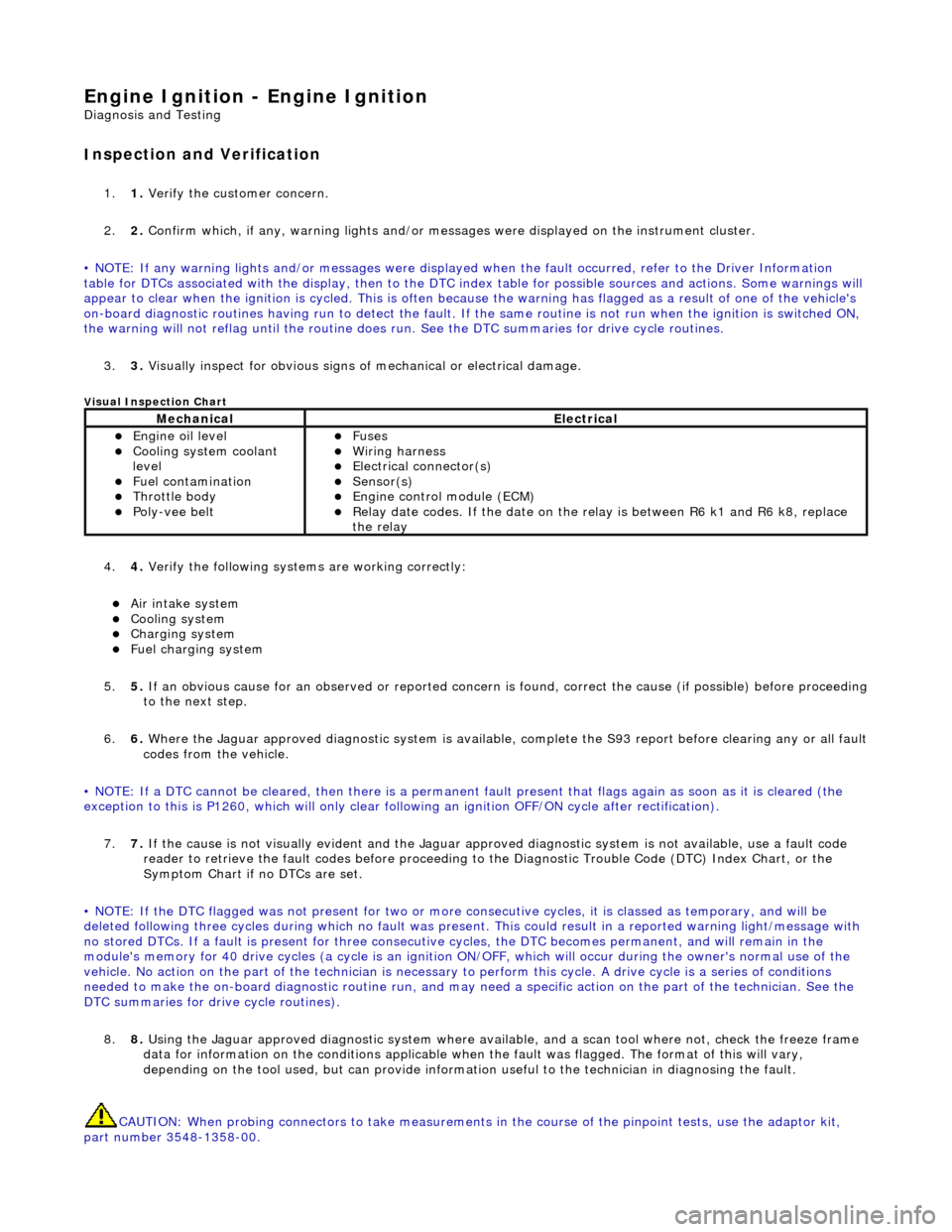
isual Inspection Chart
4.
4. Veri
fy the following syst
ems are working correctly:
Air in
take system
Coo
ling system
Charging system
F
uel charging system
5. 5. If an obvious cause for an observed or reported concern is found, correct the cause (if possible) before proceeding
to the next step.
6. 6. Where the Jaguar approved diagnostic sy stem is available, complete the S93 report before clearing any or all fault
codes from the vehicle.
• NOTE: If a DTC cannot be cleared, then there is a permanent fault present that flag s again as soon as it is cleared (the
exception to this is P1260, which will only clear following an ignition OFF/ON cycle after rectification).
7. 7. If the cause is not visually evident and the Jaguar approv ed diagnostic system is not available, use a fault code
reader to retrieve the fault codes be fore proceeding to the Diagnostic Trou ble Code (DTC) Index Chart, or the
Symptom Chart if no DTCs are set.
• NOTE: If the DTC flagged was not present for two or more co nsecutive cycles, it is classed as temporary, and will be
deleted following three cycl es during which no fault was present. This could result in a reported wa rning light/message with
no stored DTCs. If a fault is present for three consecutive cycles, the DTC becomes permanent, and will remain in the
module's memory for 40 drive cycles (a cy cle is an ignition ON/OFF, which will occur during the owner's normal use of the
vehicle. No action on the part of the technician is necessary to perform this cycle. A drive cycle is a series of conditions
needed to make the on-board diagnostic ro utine run, and may need a specific action on the part of the technician. See the
DTC summaries for driv e cycle routines).
8. 8. Using the Jaguar approved diagnostic system where available, and a scan tool where not, check the freeze frame
data for information on the conditions applicable when the fault was flagged. The format of this will vary,
depending on the tool used, but can pr ovide information useful to the technician in diagnosing the fault.
CAUTION: When probing connectors to take measurements in the course of the pinpoint tests, use the adaptor kit,
part number 3548-1358-00.
MechanicalElectrical
Engi
ne oil level
Coo
ling system coolant
level
Fuel contamination
Throttle body Poly
-vee belt
F
uses
W
iring harness
E
lectrical connector(s)
Sens
or(s)
Engine
control module (ECM)
Relay date codes.
If the date on the relay is between R6 k1 and R6 k8, replace
the relay
Page 1087 of 2490
Engine Igni
tion - Ignition Coil-On-Plug LH
Re
moval and Installation
Remov
al
Installation
1. Disc
onnect battery ground cable (IMPORTANT, see SRO
86.15.19 for further information).
2. Re
move the coolant expansion tank for access.
R
emove screw.
Position tank aside an
d secu
re with suitable tie.
3. Re
move coil on-plug cover.
R
emove six bolts.
R
emove cover.
Cle
an mating faces.
4. D
etach harness from retain
ing clips as necessary and
disconnect relevant coil connector.
5. R
emove relevant ignition coil.
Re
move bolts.
Re
move coil.