Page 1632 of 3573
6A2 Ð 30 4JG2-NA/4JG2-TURBO ENGINE
13. Oil Feed Pipe: Turbo (4JG2-T Only)
·Tighten joint bolts (cylinder block and turbo
charger side) to the specified torque.
12. Water Outlet Hose: Turbo (4JG2-T Only)
·Connect to water inlet pipe of engine.
11. Water Inlet Hose: Turbo (4JG2-T Only)
·Connect to water outlet pipe.
10. Water Bypass Hose
·Water bypass hose connect to water inlet pipe.
9. Heater Hose
·Connect to heater pipe.
8. Engine Harness
·Connect five harness connecters to units on
thermostat housing.
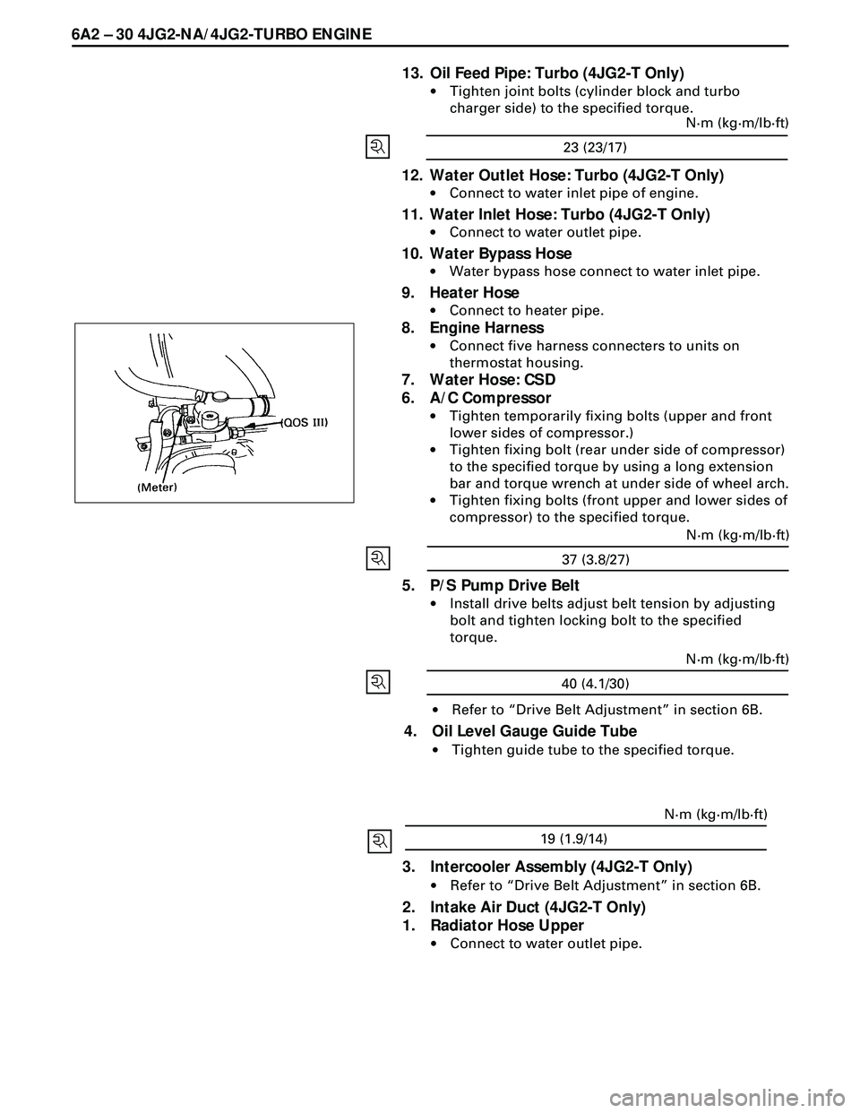
7. Water Hose: CSD
6. A/C Compressor
·Tighten temporarily fixing bolts (upper and front
lower sides of compressor.)
·Tighten fixing bolt (rear under side of compressor)
to the specified torque by using a long extension
bar and torque wrench at under side of wheel arch.
·Tighten fixing bolts (front upper and lower sides of
compressor) to the specified torque.
5. P/S Pump Drive Belt
·Install drive belts adjust belt tension by adjusting
bolt and tighten locking bolt to the specified
torque.
·Refer to ÒDrive Belt AdjustmentÓ in section 6B.
4. Oil Level Gauge Guide Tube
·Tighten guide tube to the specified torque.
23 (23/17)N·m (kg·m/lb·ft)
37 (3.8/27)N·m (kg·m/lb·ft)
40 (4.1/30)N·m (kg·m/lb·ft)
19 (1.9/14)N·m (kg·m/lb·ft)
3. Intercooler Assembly (4JG2-T Only)
·Refer to ÒDrive Belt AdjustmentÓ in section 6B.
2. Intake Air Duct (4JG2-T Only)
1. Radiator Hose Upper
·Connect to water outlet pipe.
Page 1633 of 3573
4JG2-NA/4JG2-TURBO ENGINE 6A2 Ð 31
CRANKCASE
REMOVAL
Preparation
·Disconnect battery ground cable.
·Lift up car.
·Drain engine oil.
NOTE
·Install drain plug with new gasket.
1. Transmission Housing Bolt
·Remove six fixing bolts from under side of hous-
ing.
2. Oil Return Pipe: Turbo (4JG2 -T only)
·Remove return pipe fixing nuts and set return pipe
frange from stud on crankcase.
3. Oil Pipe Clip Bolt: Vaccum Pump
4. Oil Level Gauge Guide Tube
·Remove two guide tube stay fixing bolts.
·Disconnect blow by hose and remove oil level
gauge guide tube.
Page 1634 of 3573
6A2 Ð 32 4JG2-NA/4JG2-TURBO ENGINE
5. Vacuum Hose
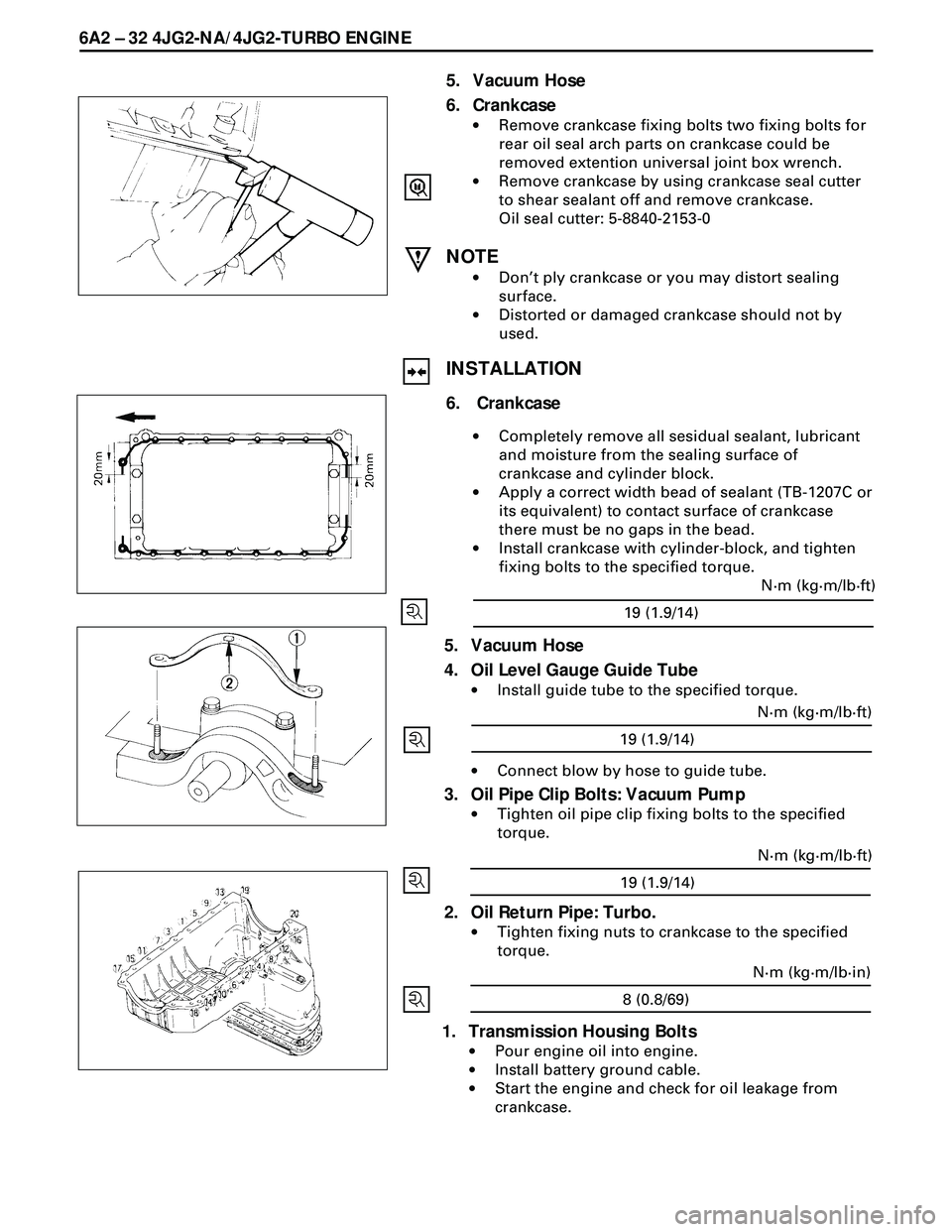
6. Crankcase
·Remove crankcase fixing bolts two fixing bolts for
rear oil seal arch parts on crankcase could be
removed extention universal joint box wrench.
·Remove crankcase by using crankcase seal cutter
to shear sealant off and remove crankcase.
Oil seal cutter: 5-8840-2153-0
NOTE
·DonÕt ply crankcase or you may distort sealing
surface.
·Distorted or damaged crankcase should not by
used.
INSTALLATION
6. Crankcase
·Completely remove all sesidual sealant, lubricant
and moisture from the sealing surface of
crankcase and cylinder block.
·Apply a correct width bead of sealant (TB-1207C or
its equivalent) to contact surface of crankcase
there must be no gaps in the bead.
·Install crankcase with cylinder-block, and tighten
fixing bolts to the specified torque.
5. Vacuum Hose
4. Oil Level Gauge Guide Tube
·Install guide tube to the specified torque.
·Connect blow by hose to guide tube.
3. Oil Pipe Clip Bolts: Vacuum Pump
·Tighten oil pipe clip fixing bolts to the specified
torque.
2. Oil Return Pipe: Turbo.
·Tighten fixing nuts to crankcase to the specified
torque.
1. Transmission Housing Bolts
·Pour engine oil into engine.
·Install battery ground cable.
·Start the engine and check for oil leakage from
crankcase.
19 (1.9/14)N·m (kg·m/lb·ft)
19 (1.9/14)N·m (kg·m/lb·ft)
19 (1.9/14)N·m (kg·m/lb·ft)
8 (0.8/69)N·m (kg·m/lb·in)
Page 1642 of 3573
6A2 Ð 40 4JG2-NA/4JG2-TURBO ENGINE
REMOVAL
1. Engine Assembly
·Refer to ÒEngine AssemblyÓ removal in this
section.
2. Crankshaft Damper Pulley
3. Timing Gear Case Cover
4. Oil Level Gauge and Guide Tube
5. Idler Gear
ÒBÓ and Shaft
6. Idler Gear
7. Injection Pump
8. Camshaft Timing Gear
9. Crankcase
10. Gear Case
11. Flywheel
12. Rear Plate
13. Connecting Rod Caps
14. Crankshaft Main Bearing Caps
15. Crankshaft and Main Bearings
INSTALLATION
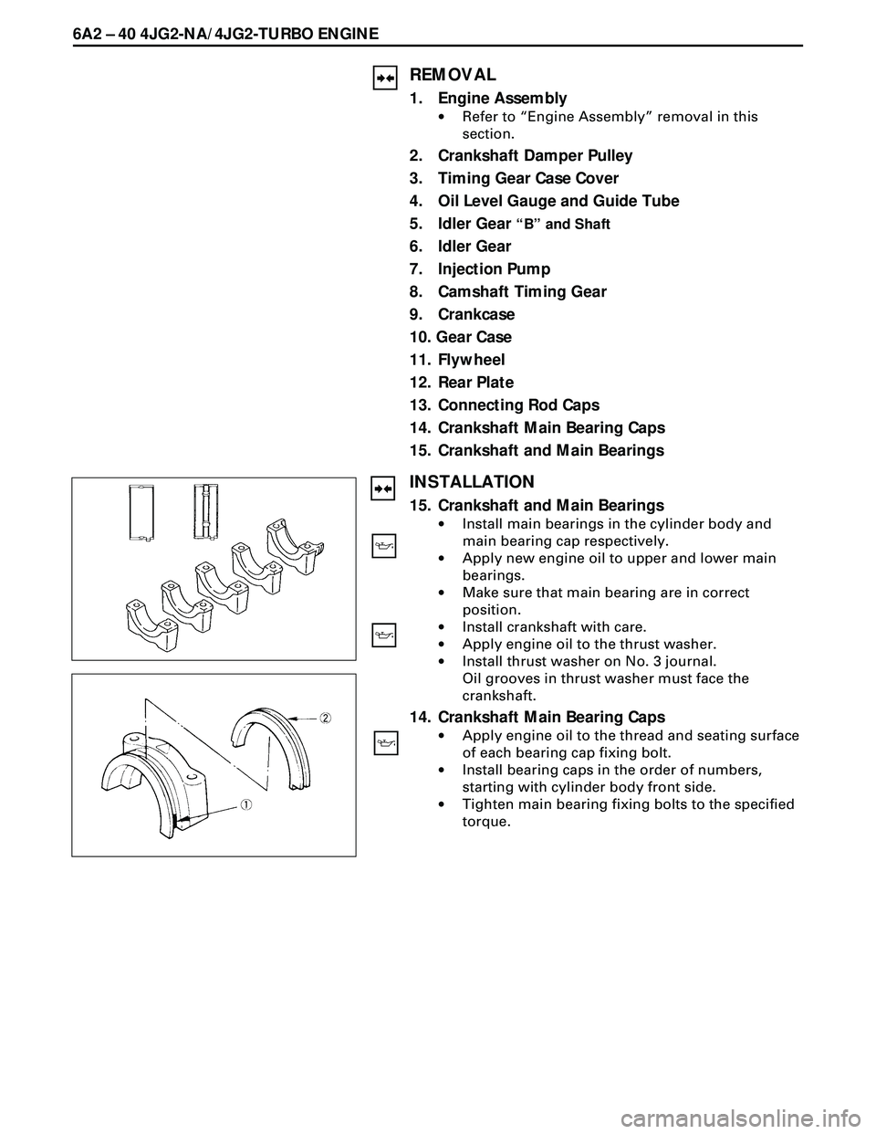
15. Crankshaft and Main Bearings
·Install main bearings in the cylinder body and
main bearing cap respectively.
·Apply new engine oil to upper and lower main
bearings.
·Make sure that main bearing are in correct
position.
·Install crankshaft with care.
·Apply engine oil to the thrust washer.
·Install thrust washer on No. 3 journal.
Oil grooves in thrust washer must face the
crankshaft.
14. Crankshaft Main Bearing Caps
·Apply engine oil to the thread and seating surface
of each bearing cap fixing bolt.
·Install bearing caps in the order of numbers,
starting with cylinder body front side.
·Tighten main bearing fixing bolts to the specified
torque.
Page 1697 of 3573
STARTING SYSTEM 6D2 Ð 3
ON-VEHICLE SERVICE
STARTER
REMOVAL
Preparation
·Battery ground cable (both batteries)
1. Oil Level Gauge and Guide
·Remove the guide and plug the hole on the oil pan.
2. Clutch Slave Cylinder
·Remove the slave cylinder and wire it to the frame.
3. Starter Wiring Connector
·Disconnect the connector from terminals ÒBÓ and
ÒSÓ.
4. Mounting
5. Starter Assembly
Page 1698 of 3573
6D2 Ð 4 STARTING SYSTEM
INSTALLATION
To install, follow the removal steps in the reverse order.
5. Starter Assembly
¥
Tighten the fixing bolt and nut to the
specified torque
4. Mounting
3. Starter Wiring Connector
·Reconnect the connectors to terminals ÒBÓ and
ÒSÓ.
2. Clutch Slave Cylinder
¥
Tighten the fixing bolt and nut to the
specified torque
78 (8.0/58)
N·m (Kg·m/lb·ft)
1. Oil Level Gauge and Guide
·Connect the battery ground cable.94 (9.6/69)
N·m (Kg·m/lb·ft)
Page 1743 of 3573
6A – 10 ENGINE MECHANICAL
8. Check the engine oil level and replenish to the
specified level if required.
9. Start the engine and check for oil leakage from the
main oil filter.
FUEL SYSTEM
Fuel filter
Replacement Procedure
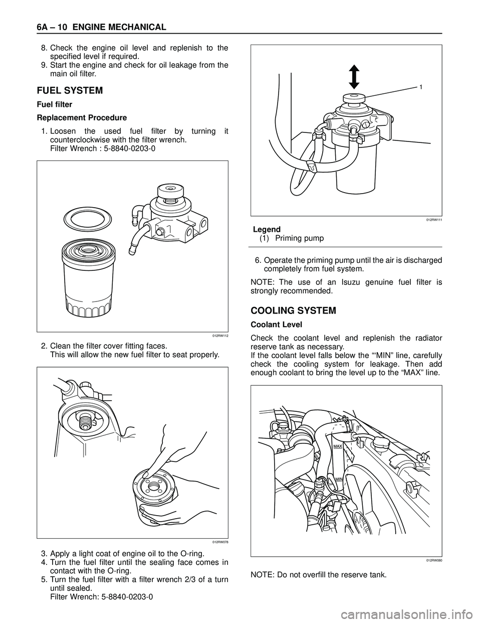
1. Loosen the used fuel filter by turning it
counterclockwise with the filter wrench.
Filter Wrench : 5-8840-0203-0
2. Clean the filter cover fitting faces.
This will allow the new fuel filter to seat properly.
3. Apply a light coat of engine oil to the O-ring.
4. Turn the fuel filter until the sealing face comes in
contact with the O-ring.
5. Turn the fuel filter with a filter wrench 2/3 of a turn
until sealed.
Filter Wrench: 5-8840-0203-0Legend
(1) Priming pump
6. Operate the priming pump until the air is discharged
completely from fuel system.
NOTE: The use of an Isuzu genuine fuel filter is
strongly recommended.
COOLING SYSTEM
Coolant Level
Check the coolant level and replenish the radiator
reserve tank as necessary.
If the coolant level falls below the “‘MIN” line, carefully
check the cooling system for leakage. Then add
enough coolant to bring the level up to the “MAX” line.
NOTE: Do not overfill the reserve tank.
012RW112
012RW078
1
012RW111
012RW080
Page 1768 of 3573
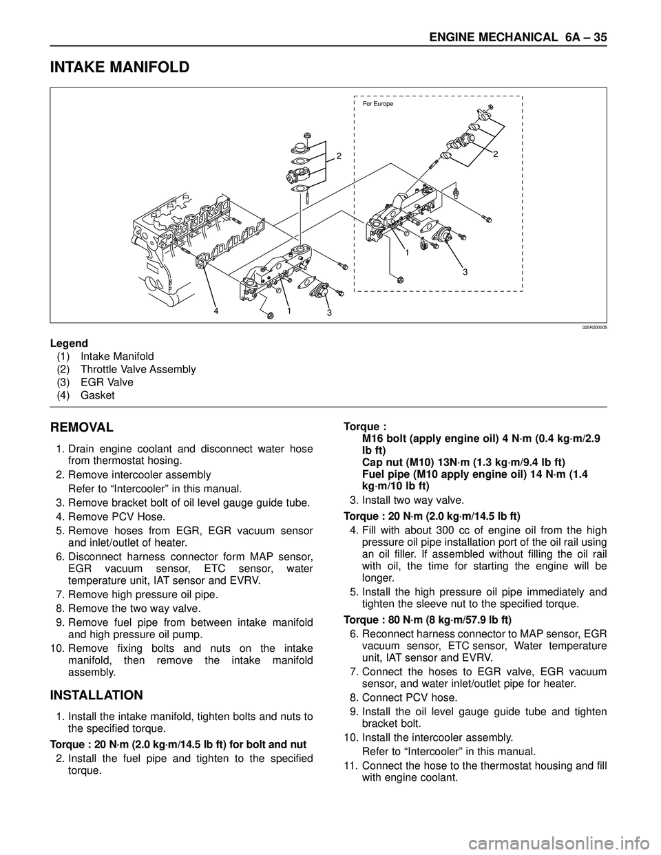
ENGINE MECHANICAL 6A – 35
INTAKE MANIFOLD
REMOVAL
1. Drain engine coolant and disconnect water hose
from thermostat hosing.
2. Remove intercooler assembly
Refer to “Intercooler” in this manual.
3. Remove bracket bolt of oil level gauge guide tube.
4. Remove PCV Hose.
5. Remove hoses from EGR, EGR vacuum sensor
and inlet/outlet of heater.
6. Disconnect harness connector form MAP sensor,
EGR vacuum sensor, ETC sensor, water
temperature unit, IAT sensor and EVRV.
7. Remove high pressure oil pipe.
8. Remove the two way valve.
9. Remove fuel pipe from between intake manifold
and high pressure oil pump.
10. Remove fixing bolts and nuts on the intake
manifold, then remove the intake manifold
assembly.
INSTALLATION
1. Install the intake manifold, tighten bolts and nuts to
the specified torque.
Torque : 20 N·m (2.0 kg·m/14.5 lb ft) for bolt and nut
2. Install the fuel pipe and tighten to the specified
torque.Torque :
M16 bolt (apply engine oil) 4 N·m (0.4 kg·m/2.9
lb ft)
Cap nut (M10) 13N·m (1.3 kg·m/9.4 lb ft)
Fuel pipe (M10 apply engine oil) 14 N·m (1.4
kg·m/10 lb ft)
3. Install two way valve.
Torque : 20 N·m (2.0 kg·m/14.5 lb ft)
4. Fill with about 300 cc of engine oil from the high
pressure oil pipe installation port of the oil rail using
an oil filler. If assembled without filling the oil rail
with oil, the time for starting the engine will be
longer.
5. Install the high pressure oil pipe immediately and
tighten the sleeve nut to the specified torque.
Torque : 80 N·m (8 kg·m/57.9 lb ft)
6. Reconnect harness connector to MAP sensor, EGR
vacuum sensor, ETC sensor, Water temperature
unit, IAT sensor and EVRV.
7. Connect the hoses to EGR valve, EGR vacuum
sensor, and water inlet/outlet pipe for heater.
8. Connect PCV hose.
9. Install the oil level gauge guide tube and tighten
bracket bolt.
10. Install the intercooler assembly.
Refer to “Intercooler” in this manual.
11. Connect the hose to the thermostat housing and fill
with engine coolant.
For Europe
2
1
3
3 1 42
025R200005
Legend
(1) Intake Manifold
(2) Throttle Valve Assembly
(3) EGR Valve
(4) Gasket