Page 3333 of 3573
SEATS8G±21
Disassembled View (Bench Type)
755RW033
Legend
(1) Trim Cover
(2) Pillow Assembly
(3) Band Hook Cover
(4) Pad & Frame Assembly
(5) Seat Back Assembly
(6) Release Knob
(7) Release Rod
(8) Device Cover
(9) Linkage Bush
(10) Reclining Device
(11) Connecting Shaft(12) Seat Cushion Assembly
(13) Connecting Link
(14) Seat Lock Cover
(15) Rear Seat Belt Buckle and Lock Assembly
(16) Trim Cover
(17) Stopper Rubber
(18) Mounting Bracket
(19) Frame Assembly
(20) Pad Assembly
(21) L´W´B
(22) S´W´B
Page 3334 of 3573

8G±22SEATS
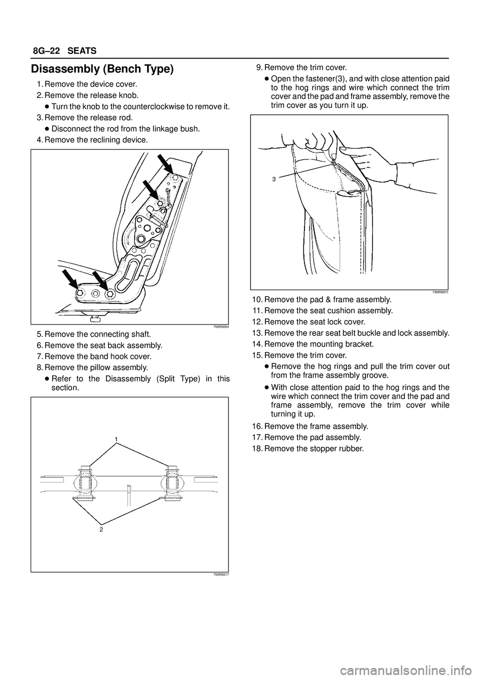
Disassembly (Bench Type)
1. Remove the device cover.
2. Remove the release knob.
�Turn the knob to the counterclockwise to remove it.
3. Remove the release rod.
�Disconnect the rod from the linkage bush.
4. Remove the reclining device.
755RS004
5. Remove the connecting shaft.
6. Remove the seat back assembly.
7. Remove the band hook cover.
8. Remove the pillow assembly.
�Refer to the Disassembly (Split Type) in this
section.
755RS017
9. Remove the trim cover.
�Open the fastener(3), and with close attention paid
to the hog rings and wire which connect the trim
cover and the pad and frame assembly, remove the
trim cover as you turn it up.
750RW011
10. Remove the pad & frame assembly.
11. Remove the seat cushion assembly.
12. Remove the seat lock cover.
13. Remove the rear seat belt buckle and lock assembly.
14. Remove the mounting bracket.
15. Remove the trim cover.
�Remove the hog rings and pull the trim cover out
from the frame assembly groove.
�With close attention paid to the hog rings and the
wire which connect the trim cover and the pad and
frame assembly, remove the trim cover while
turning it up.
16. Remove the frame assembly.
17. Remove the pad assembly.
18. Remove the stopper rubber.
Page 3335 of 3573
SEATS8G±23
Reassembly (Bench Type)
To reassemble, follow the disassembly steps in the
reverse order, noting the following point.
1. Tighten the reclining device fixing bolts to the
specified torque.
Torque: 27 N´m (2.8kg´m/20 lb ft)
2. Loosen the rubber stopper lock nut(1) and adjust the
stopper rubber(3) so there is no clearance between
the bottom of the stopper and the carpet(2), while
ensuring the rear seat is firmly locked.
Tighten the lock nut securely.
755RS005
Third Seat Assembly
Parts Location
755RW034
Legend
(1) Cover(2) Rear Side of LH
(3) Third Seat Assembly
Removal
1. Disconnect the battery ground cable.2. Remove the cover.
3. Remove the third seat assembly.
Page 3336 of 3573
8G±24SEATS
Installation
To reassemble, follow the disassembly steps in the
reverse order, noting the following point.1. Tighten the reclining device fixing bolts to the
specified torque.
Torque: 19 N´m (1.9kg´m/14 lb ft)
Disassembled View
755RW035
Legend
(1) Seat Back Assembly
(2) Pad & Frame Assembly
(3) Trim Cover
(4) Hinge Knob
(5) Hinge Cover
(6) Hinge Assembly
(7) Trim Cover
(8) Arm Bracket
(9) Bush
(10) Bracket
(11) Arm Bracket Cover
(12) Pad & Frame Assembly
(13) Seat Cushion Assembly(14) Board Assembly
(15) E±Ring
(16) Cam Bracket
(17) Tension Spring
(18) Leg Pipe Assembly
(19) Hing Pin
(20) Lock Cover
(21) Floor Lock Assembly
(22) Lock Cover
(23) Band Assembly
(24) Arm Bracket
(25) Free Hinge
(26) Free Hinge Bolt
Page 3337 of 3573

SEATS8G±25
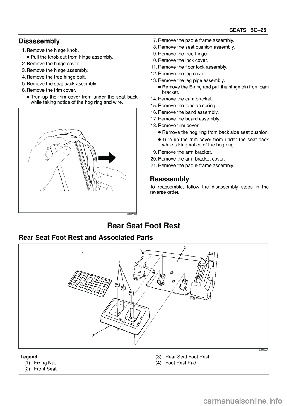
Disassembly
1. Remove the hinge knob.
�Pull the knob out from hinge assembly.
2. Remove the hinge cover.
3. Remove the hinge assembly.
4. Remove the free hinge bolt.
5. Remove the seat back assembly.
6. Remove the trim cover.
�Trun up the trim cover from under the seat back
while taking notice of the hog ring and wire.
755RW032
7. Remove the pad & frame assembly.
8. Remove the seat cushion assembly.
9. Remove the free hinge.
10. Remove the lock cover.
11. Remove the floor lock assembly.
12. Remove the leg cover.
13. Remove the leg pipe assembly.
�Remove the E-ring and pull the hinge pin from cam
bracket.
14. Remove the cam bracket.
15. Remove the tension spring.
16. Remove the band assembly.
17. Remove the board assembly.
18. Remove trim cover.
�Remove the hog ring from back side seat cushion.
�Turn up the trim cover from under the seat back
while taking notice of the hog ring.
19. Remove the arm bracket.
20. Remove the arm bracket cover.
21. Remove the pad & frame assembly.
Reassembly
To reassemble, follow the disassembly steps in the
reverse order.
Rear Seat Foot Rest
Rear Seat Foot Rest and Associated Parts
676RS001
Legend
(1) Fixing Nut
(2) Front Seat(3) Rear Seat Foot Rest
(4) Foot Rest Pad
Page 3338 of 3573
8G±26SEATS
Removal
1. Remove the foot rest pad.
676RS002
2. Remove the fixing nuts.
3. Remove the rear seat foot rest.
Installation
To install, follow the removal steps in the reverse order.
Main Data and Specifications
Torque Specifications
E10RX006
Page 3339 of 3573
Page 3383 of 3573
8J±4EXTERIOR/INTERIOR TRIM
Consoles
Consoles and Associated Parts
This illustration is based on RHD
745RW009
Legend
(1) Shift Knob (M/T) / Transfer Knob (A/T)
(2) Assist Grip
(3) Fuel Filler Lid Opener(4) Center Console Assembly
(5) Front Seat Assembly (RH)
(6) Front Console Assembly
Removal
1. Disconnect the battery ground cable.
2. Remove the shift knob (M/T) / transfer knob (A/T).
3. Remove the front console assembly.
�Remove four fixing screws and disconnect the
switch connectors.
4. Remove the front seat assembly(RH).
�Refer to the Front Seat Assembly removal steps in
Seats section.
5. Remove the assist grip.
�Remove three bolts.
6. Remove the fuel filler lid opener.
�Remove the fuel filter lid opener(1) and disconnect
the cable(2).
686RW007