Page 551 of 3573
4B1±18
DRIVE LINE CONTROL SYSTEM (SHIFT ON THE FLY)
Wiring Diagram (LHD / Gasoline Engine Model)
D08RW843
Page 552 of 3573
4B1±19 DRIVE LINE CONTROL SYSTEM (SHIFT ON THE FLY)
Wiring Diagram (RHD Model)
D08RW844
Page 553 of 3573
4B1±20
DRIVE LINE CONTROL SYSTEM (SHIFT ON THE FLY)
Wiring Diagram (RHD / Diesel Engine Model)
D08RW842
Page 554 of 3573
4B1±21 DRIVE LINE CONTROL SYSTEM (SHIFT ON THE FLY)
Wiring Diagram (RHD / Gasoline Engine Model)
D08RW638
Page 559 of 3573

4B1±26
DRIVE LINE CONTROL SYSTEM (SHIFT ON THE FLY)
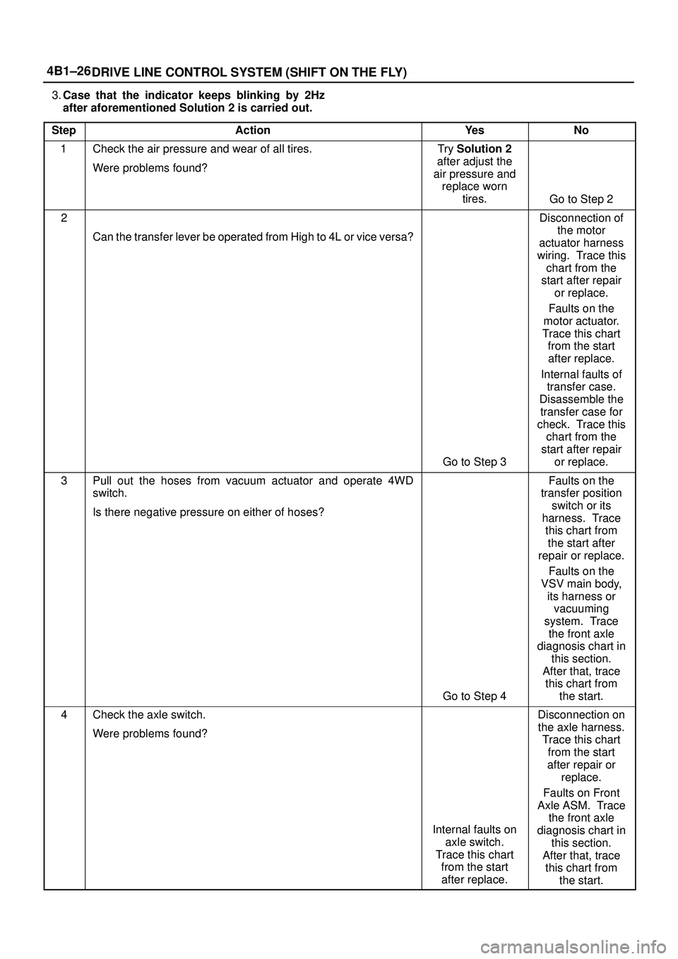
3.Case that the indicator keeps blinking by 2Hz
after aforementioned Solution 2 is carried out.
Step
ActionYe sNo
1Check the air pressure and wear of all tires.
Were problems found?Try Solution 2
after adjust the
air pressure and
replace worn
tires.
Go to Step 2
2
Can the transfer lever be operated from High to 4L or vice versa?
Go to Step 3
Disconnection of
the motor
actuator harness
wiring. Trace this
chart from the
start after repair
or replace.
Faults on the
motor actuator.
Trace this chart
from the start
after replace.
Internal faults of
transfer case.
Disassemble the
transfer case for
check. Trace this
chart from the
start after repair
or replace.
3Pull out the hoses from vacuum actuator and operate 4WD
switch.
Is there negative pressure on either of hoses?
Go to Step 4
Faults on the
transfer position
switch or its
harness. Trace
this chart from
the start after
repair or replace.
Faults on the
VSV main body,
its harness or
vacuuming
system. Trace
the front axle
diagnosis chart in
this section.
After that, trace
this chart from
the start.
4Check the axle switch.
Were problems found?
Internal faults on
axle switch.
Trace this chart
from the start
after replace.
Disconnection on
the axle harness.
Trace this chart
from the start
after repair or
replace.
Faults on Front
Axle ASM. Trace
the front axle
diagnosis chart in
this section.
After that, trace
this chart from
the start.
Page 561 of 3573

4B1±28
DRIVE LINE CONTROL SYSTEM (SHIFT ON THE FLY)
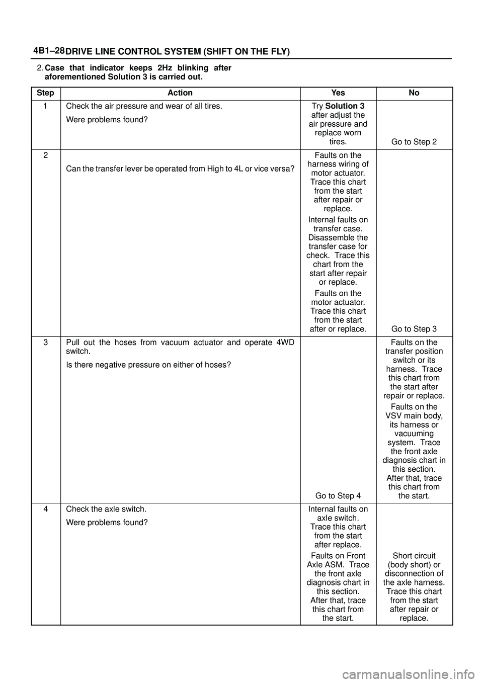
2.Case that indicator keeps 2Hz blinking after
aforementioned Solution 3 is carried out.
Step
ActionYe sNo
1Check the air pressure and wear of all tires.
Were problems found?Try Solution 3
after adjust the
air pressure and
replace worn
tires.
Go to Step 2
2
Can the transfer lever be operated from High to 4L or vice versa?
Faults on the
harness wiring of
motor actuator.
Trace this chart
from the start
after repair or
replace.
Internal faults on
transfer case.
Disassemble the
transfer case for
check. Trace this
chart from the
start after repair
or replace.
Faults on the
motor actuator.
Trace this chart
from the start
after or replace.
Go to Step 3
3Pull out the hoses from vacuum actuator and operate 4WD
switch.
Is there negative pressure on either of hoses?
Go to Step 4
Faults on the
transfer position
switch or its
harness. Trace
this chart from
the start after
repair or replace.
Faults on the
VSV main body,
its harness or
vacuuming
system. Trace
the front axle
diagnosis chart in
this section.
After that, trace
this chart from
the start.
4Check the axle switch.
Were problems found?Internal faults on
axle switch.
Trace this chart
from the start
after replace.
Faults on Front
Axle ASM. Trace
the front axle
diagnosis chart in
this section.
After that, trace
this chart from
the start.
Short circuit
(body short) or
disconnection of
the axle harness.
Trace this chart
from the start
after repair or
replace.
Page 562 of 3573
4B1±29 DRIVE LINE CONTROL SYSTEM (SHIFT ON THE FLY)
3.Case that indicator's blinking changes to 4Hz
after aforementioned Solution 4 is carried out.
Step
ActionYe sNo
1
Can the transfer lever be operated from High to 4L or vice versa?
Faults on the
harness wiring of
motor actuator.
Trace this chart
from the start
after repair or
replace.
Faults on the
motor actuator.
Trace this chart
from the start
after replace.
Internal faults on
transfer case.
Disassemble the
transfer case for
check. Trace this
chart from the
start after repair
or replace.
Faults on the
4WD control unit.
Trace this chart
from the start
after replace.
Page 567 of 3573

4B1±34
DRIVE LINE CONTROL SYSTEM (SHIFT ON THE FLY)
4. If vacuum is not applicable as much as ±400mmHg,
and if there is resistance on the intake side, replace
with a new check valve.
VSV Assembly
Inspect the vehicle side harness as follows:
412RS071
Legend
(1) Grey
(2) Blue
1. Remove connector.
2. Shift transfer lever to 2H and start the engine.
NOTE: Do not move the vehicle while inspection.
3. Make sure that there is continuity in the vehicle side of
harness. If there is no continuity, check transfer shift
switch and wiring.
Inspect both VSVs as follows:
F04RS004
1. With battery not connected (Usual).
A±C:There is continuity
B:Closed
2. With battery connected
A ± B:There is continuity
C:Closed
3. If 1) and 2) fail, replace with a new VSV.
Axle Position Switch
412RS048
1. With ball (1) being free
A ± B:There is continuity
2. With ball forced into the switch
A ± B:No continuity
3. If 1) and 2) fail, replace with a new switch.
Motor Actuator Assembly
Inspect the function of the motor actuator assembly as
follows: