1998 ISUZU TROOPER Wiring
[x] Cancel search: WiringPage 388 of 3573

2A – 86 SUPPLEMENTAL RESTRAINT SYSTEM STEERING WHEEL & COLUMN
INSTALLATION
11. Steering column assembly
Align the setting marks on the universal joint and
steering shaft made during removal.
Tighten the steering column fixing bolt (dash panel)
to the specified torque.
Steering Column Bolt Torque N·m (kg·m/lb·ft)
19 (1.9 / 14)
Tighten the steering column fixing bolt ( pedal
bracket) to the specified torque.
Steering Column Bolt Torque N·m (kg·m/lb·ft)
17 (1.7 / 13)
Tighten the universal joint to the specified torque.
Universal Joint Torque N·m (kg·m/lb·ft)
25 (2.5 / 18)
10. Lock cylinder assembly
9. Shift lock cable (for A/T)
8. Cushion rubber
7. Snap ring
6. Combination switch
After installation of combination switch assembly,
connect the combination switch wiring harness
connector.
5. Steering column cover
4. Steering wheel
Align the setting marks made when removing.
CAUTION:
Never apply force to the steering wheel in direction of the
shaft by using a hammer or other impact tools in an
attempt to remove the steering wheel. The steering shaft
is designed as an energy absorbing unit.
Tighten the steering wheel fixing nut to the specified
torque.
Steering wheel Nut Torque N·m (kg·m/lb·ft)
34 (3.5 / 25)
3. Steering lower cover
Install the engine hood opening lever.
2. Lower cluster assembly
1. Front console assembly
Connect the wiring harness connectors.
Install the transmission (for M/T) and transfer control
Page 438 of 3573

4A1±1 DIFFERENTIAL (FRONT)
DRIVELINE/AXLE
CONTENTS
Differential (Front) 4A1. . . . . . . . . . . . . . . . . . . . . . .
Differential (Rear/220mm) 4A2A. . . . . . . . . . . . . . . .
Differential (Rear/244mm) 4A2B. . . . . . . . . . . . . . . .
Driveline Control System (Shift on the Fly) 4B1. . Driveline Control System (TOD) 4B2. . . . . . . . . . .
Driveshaft System 4C. . . . . . . . . . . . . . . . . . . . . . .
Transfer Case (Standard Type) 4D1. . . . . . . . . . .
Transfer Case (TOD) 4D2. . . . . . . . . . . . . . . . . . . .
DIFFERENTIAL (FRONT)
CONTENTS
Service Precaution 4A1±1. . . . . . . . . . . . . . . . . . . . . .
Front Drive Axle 4A1±2. . . . . . . . . . . . . . . . . . . . . . . . .
Diagnosis 4A1±2. . . . . . . . . . . . . . . . . . . . . . . . . . . . .
Pinion Shaft Oil Seal 4A1±3. . . . . . . . . . . . . . . . . . . . .
Pinion Shaft Oil Seal and Associated Parts 4A1±3
Removal 4A1±3. . . . . . . . . . . . . . . . . . . . . . . . . . . . .
Inspection and Repair 4A1±4. . . . . . . . . . . . . . . . . .
Installation 4A1±4. . . . . . . . . . . . . . . . . . . . . . . . . . . .
Front Drive Axle Assembly 4A1±5. . . . . . . . . . . . . . .
Front Drive Axle Assembly and
Associated Parts 4A1±5. . . . . . . . . . . . . . . . . . . . . .
Removal 4A1±5. . . . . . . . . . . . . . . . . . . . . . . . . . . . . Installation 4A1±7. . . . . . . . . . . . . . . . . . . . . . . . . . . .
Differential Assembly 4A1±9. . . . . . . . . . . . . . . . . . . .
Disassembled View 4A1±9. . . . . . . . . . . . . . . . . . . .
Disassembly 4A1±9. . . . . . . . . . . . . . . . . . . . . . . . . .
Reassembly 4A1±12. . . . . . . . . . . . . . . . . . . . . . . . . .
Differential Cage Assembly 4A1±21. . . . . . . . . . . . . . .
Disassembled View 4A1±21. . . . . . . . . . . . . . . . . . . .
Disassembly 4A1±21. . . . . . . . . . . . . . . . . . . . . . . . . .
Inspection and Repair 4A1±22. . . . . . . . . . . . . . . . . .
Reassembly 4A1±23. . . . . . . . . . . . . . . . . . . . . . . . . .
Main Data and Specifications 4A1±25. . . . . . . . . . .
Special Tools 4A1±28. . . . . . . . . . . . . . . . . . . . . . . . . .
Service Precaution
WARNING: I F S O E Q U IPPED WITH A
SUPPLEMENTAL RESTRAINT SYSTEM (SRS),
REFER TO THE SRS COMPONENT AND WIRING
LOCATION VIEW IN ORDER TO DETERMINE
WHETHER YOU ARE PERFORMING SERVICE ON OR
NEAR THE SRS COMPONENTS OR THE SRS
WIRING. WHEN YOU ARE REFORMING SERVICE ON
OR NEAR THE SRS COMPONENTS OR THE SRS
WIRING, REFER TO THE SRS SERVICE
INFORMATION. FAILURE TO FOLLOW WARNINGS
COULD RESULT IN POSSIBLE AIR BAG
DEPLOYMENT, PERSONAL INJURY, OR
OTHERWISE UNNEEDED SRS SYSTEM REPAIRS.CAUTION: Always use the correct fastener in the
proper location. When you replace a fastener, use
ONLY the exact part number for that application.
ISUZU will call out those fasteners that require a
replacement after removal. ISUZU will also call out
the fasteners that require thread lockers or thread
sealant. UNLESS OTHERWISE SPECIFIED , do not
use supplemental coatings (Paints, greases, or other
corrosion inhibitors) on threaded fasteners or
fastener joint interfaces. Generally,such coatings
adversely affect the fastener torque and the joint
clamping force, and may damage the fastener. When
you install fasteners, use the correct tightening
sequence and specification. Following these
instructions can help you avoid damage to parts and
systems.
Page 468 of 3573

DIFFERENTIAL (REAR 220mm)
4A2A±1
DRIVELINE/AXLE
DIFFERENTIAL (Rear 220mm)
CONTENTS
Service Precaution 4A2A±1. . . . . . . . . . . . . . . . . . . . . .
General Description 4A2A±2. . . . . . . . . . . . . . . . . . . . .
Diagnosis 4A2A±3. . . . . . . . . . . . . . . . . . . . . . . . . . . . . .
Axle Housing 4A2A±4. . . . . . . . . . . . . . . . . . . . . . . . . . .
Axle Housing and Associated Parts 4A2A±4. . . . . .
Removal 4A2A±4. . . . . . . . . . . . . . . . . . . . . . . . . . . . .
Oil Seal Replacement 4A2A±5. . . . . . . . . . . . . . . . . .
Installation 4A2A±5. . . . . . . . . . . . . . . . . . . . . . . . . . . .
Pinion Oil Seal 4A2A±6. . . . . . . . . . . . . . . . . . . . . . . . . .
Pinion Oil Seal and Associated Parts 4A2A±6. . . . .
Removal 4A2A±6. . . . . . . . . . . . . . . . . . . . . . . . . . . . .
Inspection and Repair 4A2A±7. . . . . . . . . . . . . . . . . .
Installation 4A2A±7. . . . . . . . . . . . . . . . . . . . . . . . . . . .
Differential Assembly 4A2A±8. . . . . . . . . . . . . . . . . . . .
Differential Assembly and Associated Parts 4A2A±8
Removal 4A2A±8. . . . . . . . . . . . . . . . . . . . . . . . . . . . . Installation 4A2A±9. . . . . . . . . . . . . . . . . . . . . . . . . . . .
Disassembled View 4A2A±10. . . . . . . . . . . . . . . . . . . .
Disassembly 4A2A±11. . . . . . . . . . . . . . . . . . . . . . . . . .
Reassembly 4A2A±13. . . . . . . . . . . . . . . . . . . . . . . . . .
Differential Cage Assembly 4A2A±21. . . . . . . . . . . . . . .
Disassembled View 4A2A±21. . . . . . . . . . . . . . . . . . . .
Disassembly 4A2A±21. . . . . . . . . . . . . . . . . . . . . . . . . .
Inspection and Repair 4A2A±22. . . . . . . . . . . . . . . . . .
Reassembly 4A2A±23. . . . . . . . . . . . . . . . . . . . . . . . . .
Limited Slip Differential 4A2A±25. . . . . . . . . . . . . . . . . . .
Disassembled View 4A2A±25. . . . . . . . . . . . . . . . . . . .
Disassembly 4A2A±26. . . . . . . . . . . . . . . . . . . . . . . . . .
Inspection and Repair 4A2A±26. . . . . . . . . . . . . . . . . .
Reassembly 4A2A±28. . . . . . . . . . . . . . . . . . . . . . . . . .
Main Data and Specifications 4A2A±32. . . . . . . . . . .
Special Tools 4A2A±34. . . . . . . . . . . . . . . . . . . . . . . . . .
Service Precaution
WARNING: I F S O E Q U IPPED WITH A
SUPPLEMENTAL RESTRAINT SYSTEM (SRS),
REFER TO THE SRS COMPONENT AND WIRING
LOCATION VIEW IN ORDER TO DETERMINE
WHETHER YOU ARE PERFORMING SERVICE ON OR
NEAR THE SRS COMPONENTS OR THE SRS
WIRING. WHEN YOU ARE REFORMING SERVICE ON
OR NEAR THE SRS COMPONENTS OR THE SRS
WIRING, REFER TO THE SRS SERVICE
INFORMATION. FAILURE TO FOLLOW WARNINGS
COULD RESULT IN POSSIBLE AIR BAG
DEPLOYMENT, PERSONAL INJURY, OR
OTHERWISE UNNEEDED SRS SYSTEM REPAIRS.
CAUTION: Always use the correct fastener in the
proper location. When you replace a fastener, use
ONLY the exact part number for that application.
ISUZU will call out those fasteners that require a
replacement after removal. ISUZU will also call out
the fasteners that require thread lockers or thread
sealant. UNLESS OTHERWISE SPECIFIED , do not
use supplemental coatings (Paints, greases, or other
corrosion inhibitors) on threaded fasteners or
fastener joint interfaces. Generally,such coatings
adversely affect the fastener torque and the joint
clamping force, and may damage the fastener. When
you install fasteners, use the correct tightening
sequence and specification. Following these
instructions can help you avoid damage to parts and
systems.
Page 504 of 3573

DIFFERENTIAL (REAR 244mm)
4A2B±1
DRIVELINE/AXLE
DIFFERENTIAL (REAR 244mm)
CONTENTS
Service Precaution 4A2B±1. . . . . . . . . . . . . . . . . . . . . .
General Description 4A2B±2. . . . . . . . . . . . . . . . . . . . .
Diagnosis 4A2B±3. . . . . . . . . . . . . . . . . . . . . . . . . . . . . .
Axle Housing 4A2B±4. . . . . . . . . . . . . . . . . . . . . . . . . . .
Axle Housing and Associated Parts 4A2B±4. . . . . .
Removal 4A2B±4. . . . . . . . . . . . . . . . . . . . . . . . . . . . .
Oil Seal Replacement 4A2B±5. . . . . . . . . . . . . . . . . .
Installation 4A2B±5. . . . . . . . . . . . . . . . . . . . . . . . . . . .
Pinion Oil Seal 4A2B±6. . . . . . . . . . . . . . . . . . . . . . . . . .
Pinion Oil Seal and Associated Parts 4A2B±6. . . . .
Removal 4A2B±6. . . . . . . . . . . . . . . . . . . . . . . . . . . . .
Inspection and Repair 4A2B±7. . . . . . . . . . . . . . . . . .
Installation 4A2B±7. . . . . . . . . . . . . . . . . . . . . . . . . . . .
Differential Assembly 4A2B±8. . . . . . . . . . . . . . . . . . . .
Differential Assembly and Associated Parts 4A2B±8
Removal 4A2B±8. . . . . . . . . . . . . . . . . . . . . . . . . . . . . Installation 4A2B±9. . . . . . . . . . . . . . . . . . . . . . . . . . . .
Disassembled View 4A2B±10. . . . . . . . . . . . . . . . . . . .
Disassembly 4A2B±11. . . . . . . . . . . . . . . . . . . . . . . . . .
Reassembly 4A2B±13. . . . . . . . . . . . . . . . . . . . . . . . . .
Differential Cage Assembly 4A2B±20. . . . . . . . . . . . . . .
Disassembled View 4A2B±20. . . . . . . . . . . . . . . . . . . .
Disassembly 4A2B±21. . . . . . . . . . . . . . . . . . . . . . . . . .
Inspection and Repair 4A2B±21. . . . . . . . . . . . . . . . . .
Reassembly 4A2B±21. . . . . . . . . . . . . . . . . . . . . . . . . .
Locking Differential Assembly 4A2B±23. . . . . . . . . . . . .
Disassembled View 4A2B±23. . . . . . . . . . . . . . . . . . . .
Disassembly 4A2B±23. . . . . . . . . . . . . . . . . . . . . . . . . .
Inspection and Repair 4A2B±25. . . . . . . . . . . . . . . . . .
Reassembly 4A2B±25. . . . . . . . . . . . . . . . . . . . . . . . . .
Main Data and Specifications 4A2B±27. . . . . . . . . . . . .
Special Tools 4A2B±29. . . . . . . . . . . . . . . . . . . . . . . . . . .
Service Precaution
WARNING: I F S O E Q U IPPED WITH A
SUPPLEMENTAL RESTRAINT SYSTEM (SRS),
REFER TO THE SRS COMPONENT AND WIRING
LOCATION VIEW IN ORDER TO DETERMINE
WHETHER YOU ARE PERFORMING SERVICE ON OR
NEAR THE SRS COMPONENTS OR THE SRS
WIRING. WHEN YOU ARE REFORMING SERVICE ON
OR NEAR THE SRS COMPONENTS OR THE SRS
WIRING, REFER TO THE SRS SERVICE
INFORMATION. FAILURE TO FOLLOW WARNINGS
COULD RESULT IN POSSIBLE AIR BAG
DEPLOYMENT, PERSONAL INJURY, OR
OTHERWISE UNNEEDED SRS SYSTEM REPAIRS.
CAUTION: Always use the correct fastener in the
proper location. When you replace a fastener, use
ONLY the exact part number for that application.
ISUZU will call out those fasteners that require a
replacement after removal. ISUZU will also call out
the fasteners that require thread lockers or thread
sealant. UNLESS OTHERWISE SPECIFIED , do not
use supplemental coatings (Paints, greases, or other
corrosion inhibitors) on threaded fasteners or
fastener joint interfaces. Generally,such coatings
adversely affect the fastener torque and the joint
clamping force, and may damage the fastener. When
you install fasteners, use the correct tightening
sequence and specification. Following these
instructions can help you avoid damage to parts and
systems.
Page 534 of 3573

4B1±1 DRIVE LINE CONTROL SYSTEM (SHIFT ON THE FLY)
DRIVELINE/AXLE
DRIVELINE CONTROL SYSTEM (SHIFT ON THE FLY)
CONTENTS
Service Precaution 4B1±1. . . . . . . . . . . . . . . . . . . . . .
Shift on the Fly System (Lever Type) 4B1±2. . . . . . .
Outline of Shift on the Fly System
(Lever Type) 4B1±2. . . . . . . . . . . . . . . . . . . . . . . . . . .
Shift on the Fly Vacuum Piping and Electric
Equipment (For Lever Control Type) 4B1±3. . . . . .
Vacuum Piping Diagram 4B1±3. . . . . . . . . . . . . . . .
Inspection and Repair 4B1±4. . . . . . . . . . . . . . . . . .
Shift on the Fly System (Push Button Type) 4B1±7.
Outline of Shift on the Fly System
(Push Button Type) 4B1±7. . . . . . . . . . . . . . . . . . . . Functions of Indicator Lamp 4B1±11. . . . . . . . . . . . . . .
Diagnosis 4B1±11. . . . . . . . . . . . . . . . . . . . . . . . . . . . .
Front Axle Diagnosis 4B1±30. . . . . . . . . . . . . . . . . . .
Shift on the Fly Vacuum Piping and Electric
Equipment (For Push Button Type) 4B1±32. . . . . . . .
Vacuum Piping Diagram 4B1±32. . . . . . . . . . . . . . . .
Inspection and Repair 4B1±33. . . . . . . . . . . . . . . . . .
4WD Control Unit (For Push Button Type) 4B1±36. .
4WD Control Unit Associated Parts 4B1±36. . . . . .
Removal 4B1±37. . . . . . . . . . . . . . . . . . . . . . . . . . . . .
Installation 4B1±37. . . . . . . . . . . . . . . . . . . . . . . . . . . .
Service Precaution
WARNING: I F S O E Q U IPPED WITH A
SUPPLEMENTAL RESTRAINT SYSTEM (SRS),
REFER TO THE SRS COMPONENT AND WIRING
LOCATION VIEW IN ORDER TO DETERMINE
WHETHER YOU ARE PERFORMING SERVICE ON OR
NEAR THE SRS COMPONENTS OR THE SRS
WIRING. WHEN YOU ARE PERFORMING SERVICE
ON OR NEAR THE SRS COMPONENTS OR THE SRS
WIRING, REFER TO THE SRS SERVICE
INFORMATION. FAILURE TO FOLLOW WARNINGS
COULD RESULT IN POSSIBLE AIR BAG
DEPLOYMENT, PERSONAL INJURY, OR
OTHERWISE UNNEEDED SRS SYSTEM REPAIRS.
CAUTION: Always use the correct fastener in the
proper location. When you replace a fastener, use
ONLY the exact part number for that application.
ISUZU will call out those fasteners that require a
replacement after removal. ISUZU will also call out
the fasteners that require thread lockers or thread
sealant. UNLESS OTHERWISE SPECIFIED, do not
use supplemental coatings (Paints, greases, or other
corrosion inhibitors) on threaded fasteners or
fastener joint interfaces. Generally, such coatings
adversely affect the fastener torque and the joint
clamping force, and may damage the fastener. When
you install fasteners, use the correct tightening
sequence and specifications. Following these
instructions can help you avoid damage to parts and
systems.
Page 538 of 3573

4B1±5 DRIVE LINE CONTROL SYSTEM (SHIFT ON THE FLY)
4. If vacuum is not applicable as much as ±400mmHg,
and if there is resistance on the intake side, replace
with a new check valve.
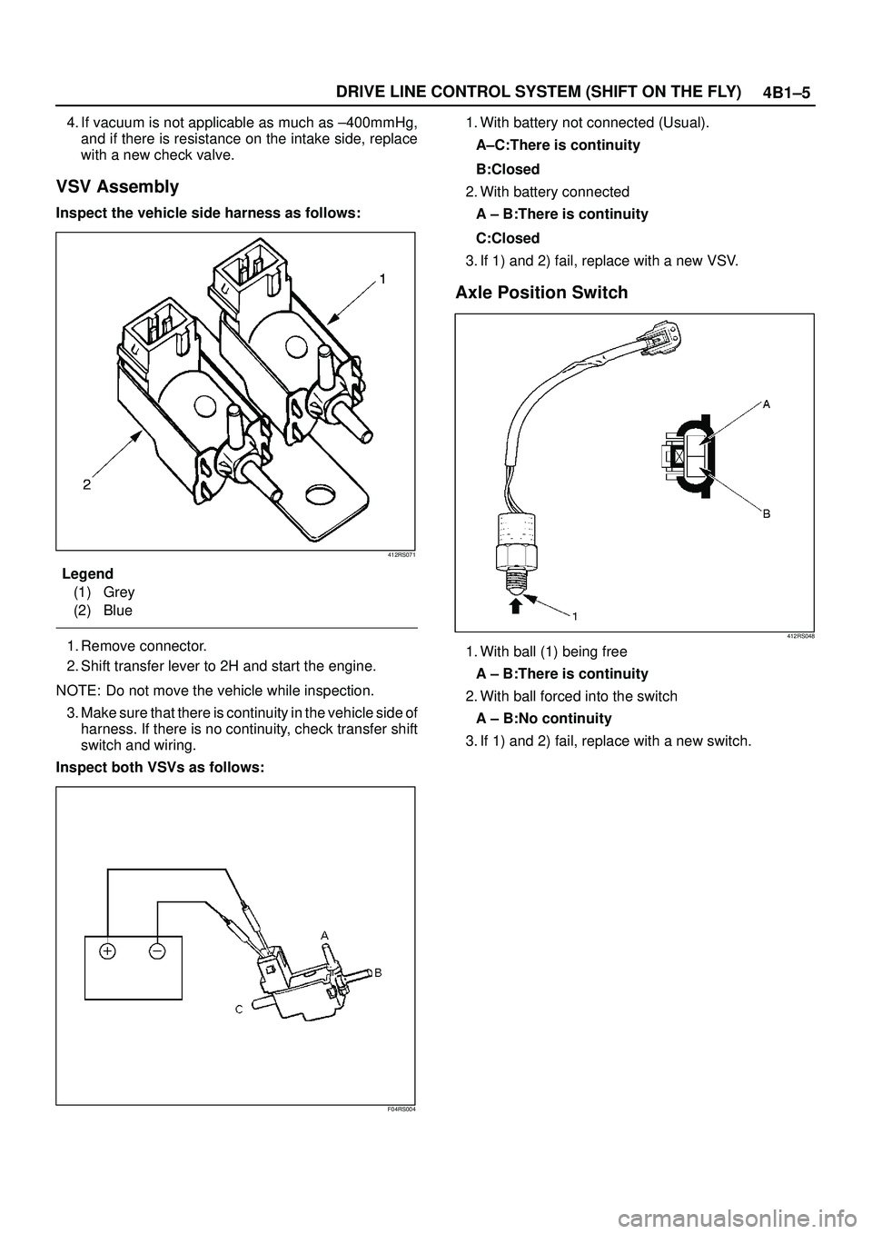
VSV Assembly
Inspect the vehicle side harness as follows:
412RS071
Legend
(1) Grey
(2) Blue
1. Remove connector.
2. Shift transfer lever to 2H and start the engine.
NOTE: Do not move the vehicle while inspection.
3. Make sure that there is continuity in the vehicle side of
harness. If there is no continuity, check transfer shift
switch and wiring.
Inspect both VSVs as follows:
F04RS004
1. With battery not connected (Usual).
A±C:There is continuity
B:Closed
2. With battery connected
A ± B:There is continuity
C:Closed
3. If 1) and 2) fail, replace with a new VSV.
Axle Position Switch
412RS048
1. With ball (1) being free
A ± B:There is continuity
2. With ball forced into the switch
A ± B:No continuity
3. If 1) and 2) fail, replace with a new switch.
Page 549 of 3573

4B1±16
DRIVE LINE CONTROL SYSTEM (SHIFT ON THE FLY)
Wiring Diagram (LHD Model)
D08RW845
Page 550 of 3573

4B1±17 DRIVE LINE CONTROL SYSTEM (SHIFT ON THE FLY)
Wiring Diagram (LHD / Diesel Engine Model)
D08RW841