Page 2327 of 3573
MANUAL TRANSMISSION7B±9
16. Remove the slave cylinder heat protector.
17. Remove the harness heat protector (6VE1).
(6VE1)
225RW006
18. Remove two transmission harness clamps and
bracket (6VE1).
19. Remove the slave cylinder.
206RW002
20. Remove the two dust cover from transmission case.
21. Support the transfer case with a jack.22. Remove two engine rear mount nuts.
(6VE1)
022RT002
23. Remove third crossmember (6VE1).
24. Remove third crossmember with rear mount rubber
(4JX1).
(4JX1)
022RW013
25. Remove two engine rear mount bolts (6VE1).
26. Remove the rear mount from the transmission
(6VE1).
27. Remove three flywheel under cover (6VE1).
Page 2331 of 3573
MANUAL TRANSMISSION7B±13
(4JX1)
225RW020
5. Apply a force of about 113N (26 Ib) to the tip of the
shift fork in the direction of the transmission to engage
the clutch pressure plate and release bearing.
NOTE: A clicking sound is heard when the release
bearing and the tip of the diaphragm spring engage each
other.
Check to see if they are securely engaged by pushing the
tip of the shift fork toward the engine while applying a
force of about 25 N (5.5 lb). If the shift fork will not move,
then they are securely engaged.
220RS006
6. Install three flywheel under cover (6VE1).
Page 2517 of 3573

7C±8CLUTCH
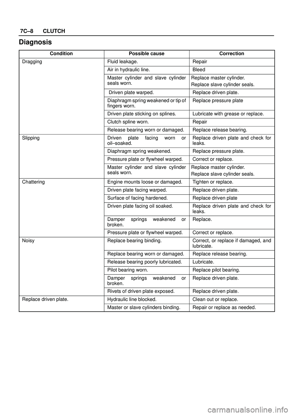
Diagnosis
ConditionPossible causeCorrection
DraggingFluid leakage.Repair
Air in hydraulic line.Bleed
Master cylinder and slave cylinder
seals worn. Replace master cylinder.
Replace slave cylinder seals.
Driven plate warped.Replace driven plate.
Diaphragm spring weakened or tip of
fingers worn. Replace pressure plate
Driven plate sticking on splines.Lubricate with grease or replace.
Clutch spline worn. Repair
Release bearing worn or damaged.Replace release bearing.
SlippingDriven plate facing worn or
oil±soaked.Replace driven plate and check for
leaks.
Diaphragm spring weakened.Replace pressure plate.
Pressure plate or flywheel warped.Correct or replace.
Master cylinder and slave cylinder
seals worn.Replace master cylinder.
Replace slave cylinder seals.
ChatteringEngine mounts loose or damaged.Tighten or replace.
Driven plate facing warped.Replace driven plate.
Surface of facing hardened.Replace driven plate
Driven plate facing oil soaked. Replace driven plate and check for
leaks.
Damper springs weakened or
broken. Replace.
Pressure plate or flywheel warped.Correct or replace.
NoisyReplace bearing binding.Correct, or replace if damaged, and
lubricate.
Replace bearing worn or damaged. Replace release bearing.
Release bearing poorly lubricated. Lubricate.
Pilot bearing worn.Replace pilot bearing.
Damper springs weakened or
broken.Replace driven plate.
Rivets of driven plate exposed.Replace driven plate.
Replace driven plate.Hydraulic line blocked.Clean out or replace.
Master or slave cylinders binding.Repair or replace as needed.
Page 2518 of 3573
CLUTCH7C±9
Clutch Assembly
Clutch Assembly and Associated Parts
201RW029
Legend
(1) Flywheel Assembly and Crankshaft Bearing
(2) Driven Plate Assembly (6VE1)
(3) Driven Plate Assembly (4JX1)
(4) Pressure Plate Assembly (5) Transmission Assembly
(6) Front Cover
(7) Shift Fork
(8) Release Bearing
Removal
1. Remove transmission assembly, refer to ºMANUAL
TRANSMISSIONº of Section 7B for ºRemoval AND
INSTALLATIONº procedure.
2. Mark the flywheel, clutch cover and pressure plate lug
for alignment when installing.
3. Remove pressure plate assembly (3).
4. Remove driven plate assembly (1) or (2). Use the pilot
aligner 5-85253-001-0 (J-24547) to prevent the
driven plate assembly from falling free.
201RW031
Page 2519 of 3573
7C±10CLUTCH
5. Mark the flywheel, clutch cover and pressure plate lug
for alignment when installing.
6. Remove the release bearing (3) from the
transmission case .
7. Remove the shift fork snap pin.
8. Remove the shift fork pin and shift fork (4) from the
front cover.
9. Remove the front cover bolts.
10. Remove the front cover (5) from the transmission
case.
220RW088
11. Remove flywheel assembly and crankshaft bearing.
Do not remove except for replacement.
12. Use the remover 5±8840±2000±0 (J±5822) and
sliding hammer 5±8840±0019±0 (J±23907) to
remove the crankshaft bearing
015RW053
Inspection and Repair
Make necessary correction or parts replacement if wear,
damage, or any other abnormal condition are found
through inspection.
Pressure Plate Assembly
201RS002
1. Visually check the pressure plate friction surface for
excessive wear and heat cracks.
2. If excessive wear or deep heat cracks are present,
the pressure plate must be replaced.
Pressure Plate Warpage
201RS003
Page 2520 of 3573

CLUTCH7C±11
1. Use a straight edge and a feeler gauge to measure
the pressure plate friction surface flatness in four
directions.
2. If any of the measured values exceeds the specified
limit, the pressure plate must be replaced.
Pressure Plate Warpage
Limit: 0.3 mm (0.012 in)
Clutch Cover
201RS004
1. Visually check the entire clutch cover for excessive
wear, cracking, and other damage.
2. The clutch cover must be replaced if any of these
conditions are present.
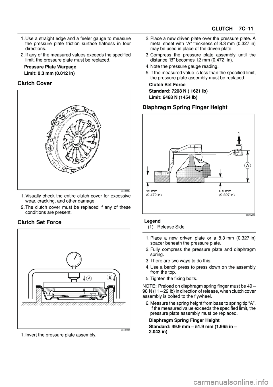
Clutch Set Force
201RS005
1. Invert the pressure plate assembly.2. Place a new driven plate over the pressure plate. A
metal sheet with ªAº thickness of 8.3 mm (0.327 in)
may be used in place of the driven plate.
3. Compress the pressure plate assembly until the
distance ªBº becomes 12 mm (0.472 in).
4. Note the pressure gauge reading.
5. If the measured value is less than the specified limit,
the pressure plate assembly must be replaced.
Clutch Set Force
Standard: 7208 N ( 1621 lb)
Limit: 6468 N (1454 lb)
Diaphragm Spring Finger Height
201RW009
Legend
(1) Release Side
1. Place a new driven plate or a 8.3 mm (0.327 in)
spacer beneath the pressure plate.
2. Fully compress the pressure plate and diaphragm
spring.
3. There are two ways to do this.
4. Use a bench press to press down on the assembly
from the top.
5. Tighten the fixing bolts.
NOTE: Preload on diaphragm spring finger must be 49 ±
98 N (11 ± 22 lb) in direction of release, when clutch cover
assembly is bolted to the flywheel.
6. Measure the spring height from base to spring tip ªAº.
If the measured value exceeds the specified limit, the
pressure plate assembly must be replaced.
Diaphragm Spring Finger Height
Standard: 49.9 mm ± 51.9 mm (1.965 in ±
2.043 in)
Page 2522 of 3573

CLUTCH7C±13
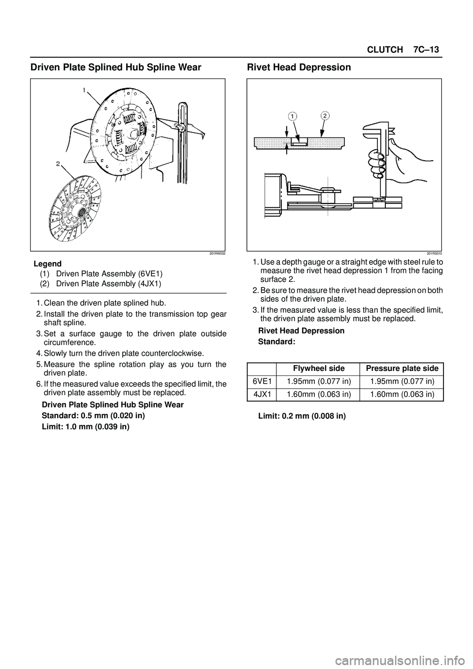
Driven Plate Splined Hub Spline Wear
201RW032
Legend
(1) Driven Plate Assembly (6VE1)
(2) Driven Plate Assembly (4JX1)
1. Clean the driven plate splined hub.
2. Install the driven plate to the transmission top gear
shaft spline.
3. Set a surface gauge to the driven plate outside
circumference.
4. Slowly turn the driven plate counterclockwise.
5. Measure the spline rotation play as you turn the
driven plate.
6. If the measured value exceeds the specified limit, the
driven plate assembly must be replaced.
Driven Plate Splined Hub Spline Wear
Standard: 0.5 mm (0.020 in)
Limit: 1.0 mm (0.039 in)
Rivet Head Depression
201RS010
1. Use a depth gauge or a straight edge with steel rule to
measure the rivet head depression 1 from the facing
surface 2.
2. Be sure to measure the rivet head depression on both
sides of the driven plate.
3. If the measured value is less than the specified limit,
the driven plate assembly must be replaced.
Rivet Head Depression
Standard:
Flywheel sidePressure plate side
6VE11.95mm (0.077 in)1.95mm (0.077 in)
4JX11.60mm (0.063 in)1.60mm (0.063 in)
Limit: 0.2 mm (0.008 in)
Page 2524 of 3573

CLUTCH7C±15
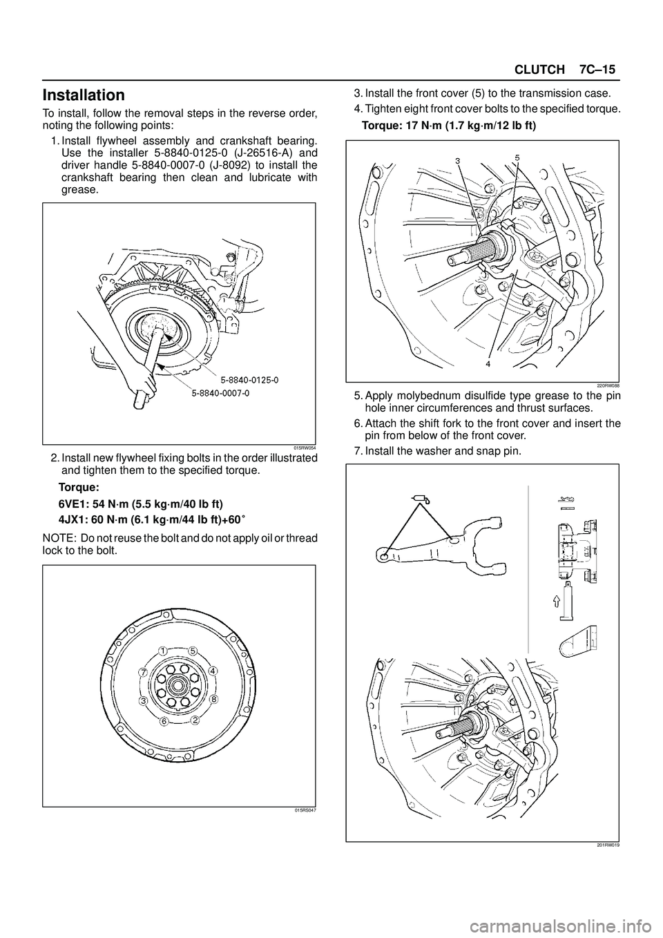
Installation
To install, follow the removal steps in the reverse order,
noting the following points:
1. Install flywheel assembly and crankshaft bearing.
Use the installer 5-8840-0125-0 (J-26516-A) and
driver handle 5-8840-0007-0 (J-8092) to install the
crankshaft bearing then clean and lubricate with
grease.
015RW054
2. Install new flywheel fixing bolts in the order illustrated
and tighten them to the specified torque.
Torque:
6VE1: 54 N´m (5.5 kg´m/40 lb ft)
4JX1: 60 N´m (6.1 kg´m/44 lb ft)+60�
NOTE: Do not reuse the bolt and do not apply oil or thread
lock to the bolt.
015RS047
3. Install the front cover (5) to the transmission case.
4. Tighten eight front cover bolts to the specified torque.
Torque: 17 N´m (1.7 kg´m/12 lb ft)
220RW088
5. Apply molybednum disulfide type grease to the pin
hole inner circumferences and thrust surfaces.
6. Attach the shift fork to the front cover and insert the
pin from below of the front cover.
7. Install the washer and snap pin.
201RW019