Page 2188 of 3573

5. Install the flywheel under cover (3 pieces), and tighten
the bolts to the specified torque.
Torque: 8 Nwm (0.8 kg´m/69 lb in)
6. Install the starter, and ti")
7A±34
AUTOMATIC TRANSMISSION (4L30±E)
5. Install the flywheel under cover (3 pieces), and tighten
the bolts to the specified torque.
Torque: 8 Nwm (0.8 kg´m/69 lb in)
6. Install the starter, and tighten the bolts to the specified
torque.
Torque: 40 Nwm (4.1 kg´m/30 lb ft)7. Connect transmission harness connectors to
transmission, and transfer.
8. Connect fuel pipe bracket to transmission side.
141RW027
9. Install transmission oil cooler pipe to transmission.
Torque: 54 Nwm (5.5 kg´m/40 lb ft)
10. Install oil pipe clamp to torque converter housing
bracket.
11. Tighten oil pipe clamp bolt at engine mount side.
12. Install exhaust pipe, and tighten the bolts to the
specified torque.
Exh. pipe to exh. manifold 67 Nwm
(6.8 kg´m/49 lb ft)
Exh. pipe flange bolt 43 Nwm (4.4 kg´m/32 lb ft)13. Connect one oxygen sensor connector to the
transmission harness.
14. Install third crossmember, and tighten the bolts to the
specified torque.
Torque: 50 Nwm (5.1 kg´m/37 lb ft)
15. Install rear mount nuts, and tighten the nuts to the
specified torque.
Torque: 50 Nwm (5.1 kg´m/37 lb ft)
16. Remove the jack from the transfer case.
Page 2199 of 3573
7A±45 AUTOMATIC TRANSMISSION (4L30±E)
242RW006
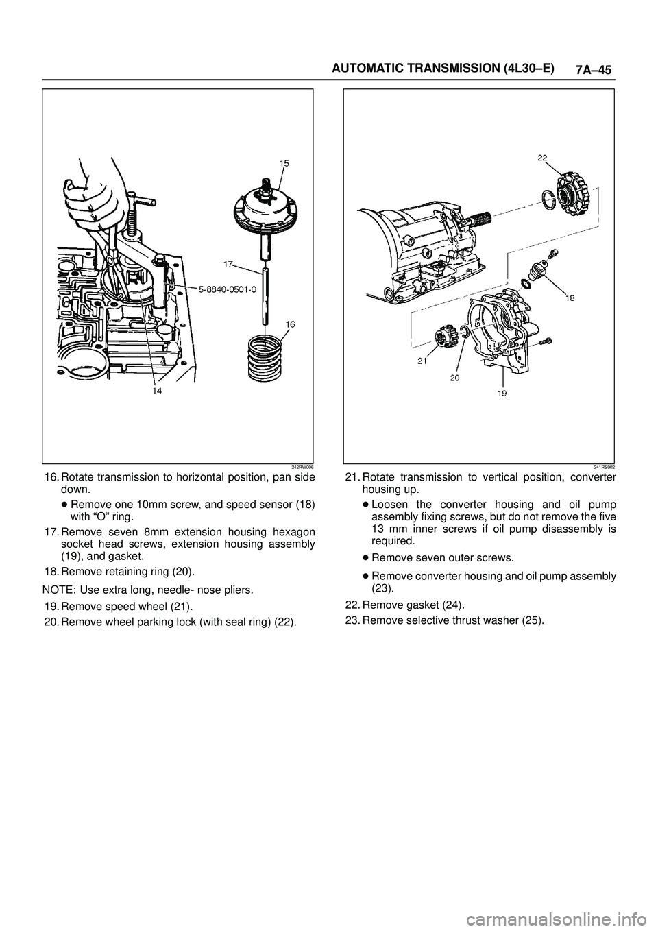
16. Rotate transmission to horizontal position, pan side
down.
�Remove one 10mm screw, and speed sensor (18)
with ªOº ring.
17. Remove seven 8mm extension housing hexagon
socket head screws, extension housing assembly
(19), and gasket.
18. Remove retaining ring (20).
NOTE: Use extra long, needle- nose pliers.
19. Remove speed wheel (21).
20. Remove wheel parking lock (with seal ring) (22).
241RS002
21. Rotate transmission to vertical position, converter
housing up.
�Loosen the converter housing and oil pump
assembly fixing screws, but do not remove the five
13 mm inner screws if oil pump disassembly is
required.
�Remove seven outer screws.
�Remove converter housing and oil pump assembly
(23).
22. Remove gasket (24).
23. Remove selective thrust washer (25).
Page 2207 of 3573

�Ensure free rotation of pump using 5±8840±2273±0
(J±23082±01) oil pump rotation tool.
241RW010
38. Overdrive clutch end play measurement.
1. Fit 5±8840±")
7A±53 AUTOMATIC TRANSMISSION (4L30±E)
�Ensure free rotation of pump using 5±8840±2273±0
(J±23082±01) oil pump rotation tool.
241RW010
38. Overdrive clutch end play measurement.
1. Fit 5±8840±2271±0 (J±25022) and
5±8840±0618±0 (J±24773±1) turbine shaft puller
on turbine shaft.
2. Position axial play checking tool on converter
housing mating face.
3. Pull turbine shaft upwards with puller until first
resistance is met. (due to weight of overdrive
assembly).
4. Maintain shaft in this position and set indicator to
zero.
5. Pull turbine shaft further upwards with puller.
Read end play shown on indicator.
End play: 0.1mm ± 0.8mm (0.004 in ± 0.031in)6. Remove axial play checking tool and puller.
NOTE: If end play is not correct, repeat selective washer
selection.
252RW010
39. Inspect extension housing oil seal and replace if
necessary, using 5±8840±2282±0 (J±36797)
extension housing oil seal installer.
�Rotate transmission to horizontal position, with
valve body side down.
�Inspect parking wheel seal ring. Replace if
necessary.
�Install wheel parking lock assembly (35).
40. Install speed wheel (36) and snap ring (37).
NOTE: Use extra long, needle-nose pliers.
41. Install gasket onto extension assembly with a thin
coating of oil.
�Install extension housing assembly (38), and align
parking pawl shaft.
�Install actuator assembly into extension assembly.
�Install seven 8 mm hexagon socket head screws.
Torque: 32 Nwm (3.3 kg´m/24 lb ft)
42. Inspect speed sensor O±ring. Replace if necessary.
�Install speed sensor assembly (39) and 10 mm
screw.
Torque: 9 Nwm (0.9 kg´m/78 lb in)
Page 2245 of 3573
7A±91 AUTOMATIC TRANSMISSION (4L30±E)
(646) Gear Assembly, Input Sun
(647) Race Assembly, Sprag
(648) Ring, Retaining/Sprag
(649) Ring, Retaining
(650) Cage Assembly, Sprag
(651) Bearing, Output Shaft/Input Sun
(652) Washer, Output Shaft/Input Sun
(653) Carrier Assembly, Planetary(658) Gear, Reaction Sun
(659) Drum, Reaction Sun
(664) Band Assembly, Brake
(667) Seal, Ring/Wheel Parking Lock
(668) Wheel, Parking Lock
(672) Wheel, Speed
(673) Ring, Retaining
(675) Bearing, Thrust Assembly
Center Support Assembly
241RS010
Legend
(701) Center Support
(702) Retainer Plate(703) Plug, Lockout
(704) Spring, Overrun Lockout
(705) Valve, Overrun Lockout
Page 2291 of 3573

DTC P0722 Transmission Output Speed Sensor (OSS) Low Input
StepActionYe sNo
11. Install the scan tool.
2. With the engine ªoffº, turn the ignition swit")
7A1±46
TRANSMISSION CONTROL SYSTEM (4L30±E)
DTC P0722 Transmission Output Speed Sensor (OSS) Low Input
StepActionYe sNo
11. Install the scan tool.
2. With the engine ªoffº, turn the ignition switch ªonº.
NOTE: Before clearing DTC(s), use the scan tool to record ªFailure
Recordsº for reference, as data will be lost when the ªClear Infoº
function is used.
3. Record the DTC ªFailure Recordsº.
4. Raise the drive wheels.
5. Start the engine.
6. Place the transmission in any drive range.
With the drive wheels rotating, does the ªTrans Output Speedº
increase with the drive wheel speed?
Go to Diagnostic
Aids
Go to Step 2
2Does the speedometer work?Go to Step 3Go to Step 4
3Check for the most current and/or incorrect calibration.
Is the calibration current?
Go to Step 16Go to Step 4
41. Turn the ignition ªoffº.
2. Disconnect the J3 (BLUE) PCM connector.
3. Using the J39200 DVOM, measure the resistance between
harness connector terminals J3±E1 and J3±E2.
Is the reading 3,000 ohms?
Go to Step 5Go to Step 6
51. Select AC volts.
2. Rotate the rear wheels, ensuring the driveshaft is turning.
Is the voltage greater than 0.5 volts?
Go to Step 7Go to Step 8
6Inspect circuits RED and WHT for a poor connection or an open
circuit.
Was a problem found?
Go to Step 17Go to Step 8
71. Reconnect the J3 (BLUE) PCM connector.
2. Disconnect the OSS harness from the OSS.
3. With the engine ªoffº, turn the ignition ªonº.
4. Using the J 39200 DVOM, measure the voltage at the OSS
harness connector terminals M15±1 and M15±2.
Is the reading between 4.0 to 5.1 volts?
Go to Step 16Go to Step 10
81. Remove the OSS.
2. Check the output shaft speed sensor rotor for damage or
misalignment. Refer to Speed Sensor (Extension Housing) in
Automatic Transmission (4L30±E) section.
Was a problem found?
Go to Step 17Go to Step 9
9Replace the OSS.
Is the replacement complete?
Go to Step 17Ð
10Was the reading in step 8 less than 4.0 volts?Go to Step 12Go to Step 11
11Was the reading in Step 8 greater than 5.1 volts?Go to Step 15Ð
12Using the J 39200 DVOM to chassis ground, measure the voltage
on circuit RED.
Is the reading between 4.0 to 5.1 volts?
Go to Step 13Go to Step 14
13Repair the open in circuit WHT.
Is the repair complete?
Go to Step 17Ð
14Check circuit RED for a short to ground or open.
Was a problem found and corrected?
Go to Step 17Go to Step 16
Page 2294 of 3573
7A1±49
DTC P0723 Transmission Output Speed Sensor (OSS) Intermittent
StepActionYe sNo
11. Install the scan tool.
2. With the engine ªoffº, turn the ignition sw")
TRANSMISSION CONTROL SYSTEM (4L30±E)7A1±49
DTC P0723 Transmission Output Speed Sensor (OSS) Intermittent
StepActionYe sNo
11. Install the scan tool.
2. With the engine ªoffº, turn the ignition switch ªonº.
NOTE: Before clearing DTC(s), use the scan tool to record ªFailure
Recordsº for reference, as data will be lost when the ªClear Infoº
function is used.
3. Record the DTC ªFailure Recordsº.
4. Raise the drive wheels.
5. Start the engine.
6. Place the transmission in any drive range.
With the drive wheels rotating, does the ªTrans Output Speedº
increase with the drive wheel speed?
Go to Diagnostic
Aids
Go to Step 2
2Does the speedometer work?Go to Step 3Go to Step 4
3Check for the most current and/or incorrect calibration.
Is the calibration current?
Go to Step 16Go to Step 4
41. Turn the ignition ªoffº.
2. Disconnect the J3 (BLUE) PCM connector.
3. Using the J39200 DVOM, measure the resistance between
harness connector terminals J3±E1 and J3±E2.
Is the reading 3,000 ohms?
Go to Step 5Go to Step 6
51. Select AC volts.
2. Rotate the rear wheels, ensuring the driveshaft is turning.
Is the voltage greater than 0.5 volts?
Go to Step 7Go to Step 8
6Inspect circuits RED and WHT for a poor connection or an open
circuit.
Was a problem found?
Go to Step 17Go to Step 8
71. Reconnect the J3 (BLUE) PCM connector.
2. Disconnect the OSS harness from the OSS.
3. With the engine ªoffº, turn the ignition ªonº.
4. Using the J 39200 DVOM, measure the voltage at the OSS
harness connector terminals M15±1 and M15±2.
Is the reading between 4.0 to 5.1 volts?
Go to Step 16Go to Step 10
81. Remove the OSS.
2. Check the output shaft speed sensor rotor for damage or
misalignment. Refer to Speed Sensor (Extension Housing) in
Automatic Transmission (4L30±E) section.
Was a problem found?
Go to Step 17Go to Step 9
9Replace the OSS.
Is the replacement complete?
Go to Step 17Ð
10Was the reading in step 8 less than 4.0 volts?Go to Step 12Go to Step 11
11Was the reading in Step 8 greater than 5.1 volts?Go to Step 15Ð
12Using the J 39200 DVOM to chassis ground, measure the voltage
on circuit RED.
Is the reading between 4.0 to 5.1 volts?
Go to Step 13Go to Step 14
13Repair the open in circuit WHT.
Is the repair complete?
Go to Step 17Ð
14Check circuit RED for a short to ground or open.
Was a problem found and corrected?
Go to Step 17Go to Step 16
Page 2322 of 3573
Replace
Gear")
7B±4MANUAL TRANSMISSION
Diagnosis
ConditionPossible causeCorrection
Abnormal noiseFlywheel pilot bearing wornReplace
Bearings worn or broken (Mainshaft,
counter shaft, and transfer shaft)Replace
Gear tooth contact surfaces worn or
scuffed (Mainshaft, counter shaft,
reverse idler gear and transfer gears)Replace
Splines worn (Mainshaft,
synchronizer clutch hub)Replace
Gear or bearing thrust face seizedReplace
Lack of backlash between meshing
gearsReplace
Hard ShiftingImproper clutch pedal free playReadjust
Change lever sliding portions wornRepair or replace
Regrease
Shift block, shift rod and/or control
box sliding faces wornReplace
Shift arm and synchronizer sleeve
groove wornReplace worn parts
Thrust washer, collar, and/or gear
thrust faces worn (Mainshaft and
counter shaft thrust play)Replace worn parts
Synchronizer parts wornReplace
Walking or Jumping out of gearDetent ball wornReplace
Detent spring weakened or brokenReplace
Shift rod and/or control box sliding
faces wornReplace
Shift arm and synchronizer sleeve
groove wornReplace worn parts
Thrust washer, collar, and/or gear
thrust faces worn (Mainshaft and
counter shaft thrust play)Replace worn parts
Bearings worn or brokenReplace
Splines worn (Mainshaft,
synchronizer hub)Replace
Synchronizer spring weakened or
brokenReplace
Oil leakageLoose drain plug(s) and/or filler
plug(s)Tighten
Replenish oil
Defective or improperly installed
gasket(s)Replace
Oil seal worn or scratchedReplace
Page 2323 of 3573
MANUAL TRANSMISSION7B±5
Manual Transmission Assembly
Transmission and Associated Parts
220RW108
Legend
(1) Gear Control Lever and Knob
(2) Transfer Control Lever and Knob
(3) Front Console Assembly
(4) Grommet Assembly
(5) Transfer Protector
(6) Rear Propeller Shaft
(7) Front Propeller Shaft
(8) Exhaust Pipe
(9) Backup Lamp, 4WD Indicator, and 1±2
Indicator Switch Harness Connector
(10) Speedometer Sensor and 2WD±4WD Actuator
Harness Connector(11) Slave Cylinder Heat Protector
(12) Harness Heat Protector
(13) Slave Cylinder
(14) Dust Cover
(15) Engine Rear Mount Nut
(16) Engine Rear Mount Bolt
(17) Engine Rear Mount
(18) Third Crossmember
(19) Flywheel Under Cover
(20) Transmission Retaining Bolt
(21) Transmission Assembly with Transfer Case

(646) Gear Assembly, Input Sun
(647) Race Assembly, Sprag
(648) Ring, Retaining/Sprag
(649) Ring, Retaining
(650) Cage Assembly, Sprag
(651) Bearing, Output Sha")
 Gear Control Lever and Knob
(2) Transfer Control Lever and Knob
(3) Front Console Assembly
(")