Page 1443 of 3573
6E±326
ENGINE DRIVEABILITY AND EMISSIONS
4. Pull the relay straight up and out of the fuse and relay
box.
TS23986
Installation Procedure
1. Insert the relay into the correct place in the fuse and
relay box with the catch slot facing forward.
2. Press down until the catch engages.
�An audible ªclickº will be heard.
3. Install the fuse and relay box cover.
TS23986
EVAP Canister Hoses
Service Information
To view the routing of the EVAP canister hoses, refer to
Vehicle Emission Control Information in Diagnosis. Use
6148M or equivalent when you replace the EVAP canister
hoses.
EVAP Canister
Removal Procedure
1. Disconnect the negative battery cable.
2. Disconnect the three hoses from the EVAP canister.
014RW145
3. Remove the retaining two bolts on the mounting
bracket and slide the canister out of mounting
bracket.
014RW146
Inspection Procedure
1. Inspect the hoses for cracks and leaks.
2. Inspect the canister for a damaged case.
Page 1746 of 3573

ENGINE MECHANICAL 6A – 13
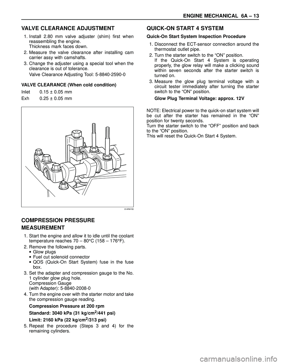
VALVE CLEARANCE ADJUSTMENT
1. Install 2.80 mm valve adjuster (shim) first when
reassembling the engine.
Thickness mark faces down.
2. Measure the valve clearance after installing cam
carrier assy with camshafts.
3. Change the adjuster using a special tool when the
clearance is out of tolerance.
Valve Clearance Adjusting Tool: 5-8840-2590-0
VALVE CLEARANCE (When cold condition)
Inlet 0.15 ± 0.05 mm
Exh 0.25 ± 0.05 mm
COMPRESSION PRESSURE
MEASUREMENT
1. Start the engine and allow it to idle until the coolant
temperature reaches 70 – 80°C (158 – 176°F).
2. Remove the following parts.
•Glow plugs
•Fuel cut solenoid connector
•QOS (Quick-On Start System) fuse in the fuse
box.
3. Set the adapter and compression gauge to the No.
1 cylinder glow plug hole.
Compression Gauge
(with Adapter): 5-8840-2008-0
4. Turn the engine over with the starter motor and take
the compression gauge reading.
Compression Pressure at 200 rpm
Standard: 3040 kPa (31 kg/cm
2/441 psi)
Limit: 2160 kPa (22 kg/cm
2/313 psi)
5. Repeat the procedure (Steps 3 and 4) for the
remaining cylinders.
QUICK-ON START 4 SYSTEM
Quick-On Start System Inspection Procedure
1. Disconnect the ECT-sensor connection around the
thermostat outlet pipe.
2. Turn the starter switch to the “ON” position.
If the Quick-On Start 4 System is operating
properly, the glow relay will make a clicking sound
within seven seconds after the starter switch is
turned on.
3. Measure the glow plug terminal voltage with a
circuit tester immediately after turning the starter
switch to the “ON” position.
Glow Plug Terminal Voltage: approx. 12V
NOTE: Electrical power to the quick-on start system will
be cut after the starter has remained in the “ON”
position for twenty seconds.
Turn the starter switch to the “OFF” position and back
to the “ON” position.
This will reset the Quick-On Start 4 System.
014RW150
Page 2110 of 3573

6E±217 4JX1±TC ENGINE DRIVEABILITY AND EMISSIONS
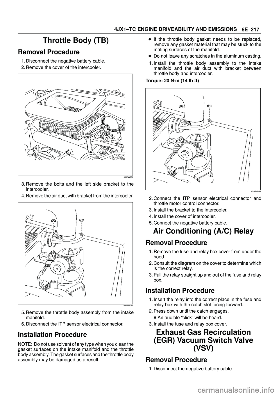
Throttle Body (TB)
Removal Procedure
1. Disconnect the negative battery cable.
2. Remove the cover of the intercooler.
035RW051
3. Remove the bolts and the left side bracket to the
intercooler.
4. Remove the air duct with bracket from the intercooler.
035RW086
5. Remove the throttle body assembly from the intake
manifold.
6. Disconnect the ITP sensor electrical connector.
Installation Procedure
NOTE: Do not use solvent of any type when you clean the
gasket surfaces on the intake manifold and the throttle
body assembly. The gasket surfaces and the throttle body
assembly may be damaged as a result.�If the throttle body gasket needs to be replaced,
remove any gasket material that may be stuck to the
mating surfaces of the manifold.
�Do not leave any scratches in the aluminum casting.
1. Install the throttle body assembly to the intake
manifold and the air duct with bracket between
throttle body and intercooler.
Torque: 20 N´m (14 Ib ft)
035RW086
2. Connect the ITP sensor electrical connector and
throttle motor control connector.
3. Install the bracket to the intercooler.
4. Install the cover of intercooler.
5. Connect the negative battery cable.
Air Conditioning (A/C) Relay
Removal Procedure
1. Remove the fuse and relay box cover from under the
hood.
2. Consult the diagram on the cover to determine which
is the correct relay.
3. Pull the relay straight up and out of the fuse and relay
box.
Installation Procedure
1. Insert the relay into the correct place in the fuse and
relay box with the catch slot facing forward.
2. Press down until the catch engages.
�An audible ªclickº will be heard.
3. Install the fuse and relay box cover.
Exhaust Gas Recirculation
(EGR) Vacuum Switch Valve
(VSV)
Removal Procedure
1. Disconnect the negative battery cable.
Page 2617 of 3573
8DÐ24 WIRING SYSTEM
12
D08RWA03
Legend
(1) Relay and Fuse Box
(2) Fuse Box
Main Data and Specifications
Fuse, Fusible Link and Circuit Breaker Location
Page 2618 of 3573
WIRING SYSTEM 8DÐ25
Relay & Fuse Box
FL-1
FL-2 FL-6 FL-5 FL-4 FL-3
F-12 F-11 F-10 F-9 F-8 F-7 F-6 F-5 F-4 F-3 F-2 F-1 RELAY AND FUSE BOX
RHD
FUSIBLE LINK FUSE
MODEL
No.
FL-1
FL-2
FL-3
FL-4
FL-5
FL-6
F-1
F-2
F-3
F-4
F-5
F-6
F-7
F-8
F-9
F-10
F-11
F-12LHD
80A MAIN
50A KEY SW
30A ECM (GASOLINE)
30A CONDENSER FAN
50A GLOW (4JG2)
40A ABS
10A O
2 SENSOR (GASOLINE)
15A HORN HAZARD
15A H/LAMP-LH
15A H/LAMP-RH
15A ANTI-THEFT
20A FOG
20A ABS
15A FUEL PUMP (GASOLINE)
15A TAIL80A MAIN
50A KEY SW
30A ECM (GASOLINE)
30A CONDENSER FAN
50A GLOW (4JG2)
40A ABS
10A O2 SENSOR (GASOLINE)
15A HORN HAZARD
10A H/LAMP-LH (HI)
10A H/LAMP-RH (HI)
10A H/LAMP-LH (LOW)
10A H/LAMP-RH (LOW)
20A FOG
20A ABS
15A FUEL PUMP (GASOLINE)
10A TAIL-LH
10A TAIL-RH —
—
——
810RS027
Page 2619 of 3573

8DÐ26 WIRING SYSTEM
Fuse Box
This illustration is based on RHD
C/B-1 C/B-2
C-10
C-20C-9 C-8 C-7 C-6 C-5 C-4 C-3 C-2 C-1
C-19 C-18 C-17 C-16 C-15 C-14 C-13 C-12 C-11
C-21 C-22 C-23 C-24
FUSE BOX
RHDNo.
C-1
C-2
C-3
C-4
C-5
C-6
C-7
C-8
C-9
C-10
C-11
C-12
C-13
C-14
C-15
C-16
C-17
C-18
C-19
C-20
C-21
C-22
C-23
C-24LHD
10A STARTER RELAY
15A SEAT HEATER
10A TURN, BACK
10A ELEC. IGN.
15A FRT WIPER AND WASHER
10A RR WIPER AND WASHER
10A H/LAMP WIPER
15A ENGINE
15A IGN. COIL (GASOLINE)
15A FUEL CUT (4JG2)
10A METER, GAUGE
10A AUDIO, MIRROR
20A CIGARETTE
10A ANTI-THEFT
15A STOP, A/T CONT.
20A TELEPHONE
10A CLOCK, ROOM
25A RR DEFOG.
20A DOOR LOCK
25A BLOWER
10A AIR CON.
10A SRS-110A STARTER RELAY
15A SEAT HEATER
10A TURN, BACK
10A ELEC. IGN.
15A FRT WIPER AND WASHER
10A RR WIPER AND WASHER
10A H/LAMP WIPER
15A ENGINE
15A IGN. COIL (GASOLINE)
15A FUEL CUT (4JG2)
10A METER, GAUGE
10A AUDIO, MIRROR
20A CIGARETTE
10A ANTI-THEFT
15A STOP, A/T CONT.
20A TELEPHONE
10A CLOCK, ROOM
25A RR DEFOG.
20A DOOR LOCK
25A BLOWER
10A AIR CON.
10A SRS-1 FUSE
RHDNo.
C/B-1
C/B-2LHD
30A P/W, P/S, S/R 30A P/W, P/S, S/R—— CIRCUIT BREAKER
—
—
——
—
—
810RV026
Page 2620 of 3573
WIRING SYSTEM 8DÐ27
Relay Location-1 (Relay and Fuse Box)
RHDNo.
X-1
X-2
X-3
X-4
X-5
X-6
X-7
X-8
X-9
X-10
X-11
X-12
X-13
X-16
X-17
X-18
X-19
X-20
X-21
X-22
X-23LHD
RELAY ; LIGHTING
RELAY ; A/C THERMO
RELAY ; COMPRESSOR (GASOLINE)
RELAY ; HORN
RELAY ; TAIL
RELAY ; FUEL PUMP (GASOLINE)
RELAY ; ECM MAIN (GASOLINE)
RELAY ; ANTI-THEFT
RELAY ; STARTER (GASOLINE)
RELAY ; CHARGE (DIESEL)
RELAY ; SHIFT ON THE FLY
RELAY ; CONDENSER FAN
(GASOLINE)
RELAY ; RR FOG LIGHT
RELAY ; FRT FOG LIGHTRELAY ; LIGHTING
RELAY ; DIMMER
RELAY ; A/C THERMO
RELAY ; COMPRESSOR (GASOLINE)
RELAY ; HORN
RELAY ; TAIL
RELAY ; FUEL PUMP (GASOLINE)
RELAY ; ECM MAIN (GASOLINE)
RELAY ; ANTI-THEFT
RELAY ; STARTER (GASOLINE)
RELAY ; CHARGE (DIESEL)
RELAY ; SHIFT ON THE FLY
RELAY ; CONDENSER FAN
RELAY ; FRT FOG LIGHT
—
—
—
—
—
—
—
——
—
—
—
—
—
—
—
X-1
X-2
X-3
X-4X-5
X-6
X-7
X-8X-9
X-10 X-12X-11X-13X-16
X-17X-18
X-19X-20
X-21
X-22
X-23 RELAY AND FUSE BOX
810RS029
Page 2621 of 3573
8DÐ28 WIRING SYSTEM
Relay Location-2 (Fuse Box)
1234
5
810RW330
Legend
(1) Heater & A/C Relay
(2) Power Window Relay
(3) H-63(4) Flasher Unit
(5) Rear Defogger Relay