1998 ISUZU TROOPER coolant level
[x] Cancel search: coolant levelPage 1530 of 3573
00 Ð 30 SERVICE INFORMATION
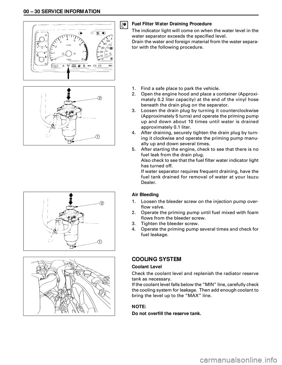
Fuel Filter Water Draining Procedure
The indicator light will come on when the water level in the
water separator exceeds the specified level.
Drain the water and foreign material from the water separa-
tor with the following procedure.
1. Find a safe place to park the vehicle.
2. Open the engine hood and place a container (Approxi-
mately 0.2 liter capacity) at the end of the vinyl hose
beneath the drain plug on the separator.
3. Loosen the drain plug by turning it counterclockwise
(Approximately 5 turns) and operate the priming pump
up and down about 10 times until water is drained
approximately 0.1 liter.
4. After draining, securely tighten the drain plug by turn-
ing it clockwise and operate the priming pump manu-
ally up and down several times.
5. After starting the engine, check to see that there is no
fuel leak from the drain plug.
Also check to see that the fuel filter water indicator light
has turned off.
If water separator requires frequent draining, have the
fuel tank drained for removal of water at your Isuzu
Dealer.
Air Bleeding
1. Loosen the bleeder screw on the injection pump over-
flow valve.
2. Operate the priming pump until fuel mixed with foam
flows from the bleeder screw.
3. Tighten the bleeder screw.
4. Operate the priming pump several times and check for
fuel leakage.
COOLING SYSTEM
Coolant Level
Check the coolant level and replenish the radiator reserve
tank as necessary.
If the coolant level falls below the ÒMINÓ line, carefully check
the cooling system for leakage. Then add enough coolant to
bring the level up to the ÒMAXÓ line.
NOTE:
Do not overfill the reserve tank.
Page 1531 of 3573
SERVICE INFORMATION 00 Ð 31
Remove the radiator filler cap only when absolutely neces-
sary.
Always check the coolant level when the engine is cold.
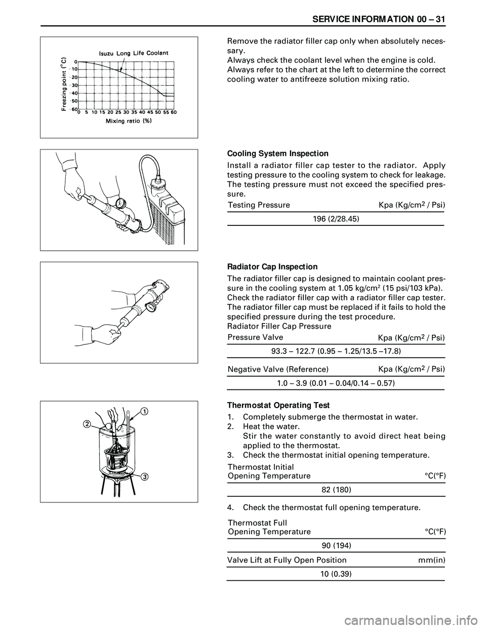
Always refer to the chart at the left to determine the correct
cooling water to antifreeze solution mixing ratio.
Cooling System Inspection
Install a radiator filler cap tester to the radiator. Apply
testing pressure to the cooling system to check for leakage.
The testing pressure must not exceed the specified pres-
sure.
Radiator Cap Inspection
The radiator filler cap is designed to maintain coolant pres-
sure in the cooling system at 1.05 kg/cm
2 (15 psi/103 kPa).
Check the radiator filler cap with a radiator filler cap tester.
The radiator filler cap must be replaced if it fails to hold the
specified pressure during the test procedure.
Radiator Filler Cap Pressure
Thermostat Operating Test
1. Completely submerge the thermostat in water.
2. Heat the water.
Stir the water constantly to avoid direct heat being
applied to the thermostat.
3. Check the thermostat initial opening temperature.
82 (180)
°C(°F) Thermostat Initial
Opening Temperature
4. Check the thermostat full opening temperature.
1.0 – 3.9 (0.01 – 0.04/0.14 – 0.57)
Negative Valve (Reference)Kpa (Kg/cm2 / Psi)
90 (194)
°C(°F) Thermostat Full
Opening Temperature
10 (0.39)
mm(in) Valve Lift at Fully Open Position
196 (2/28.45)
Testing Pressure Kpa (Kg/cm2 / Psi)
93.3 – 122.7 (0.95 – 1.25/13.5 –17.8)
Pressure Valve
Kpa (Kg/cm2 / Psi)
Page 1629 of 3573
4JG2-NA/4JG2-TURBO ENGINE 6A 2Ð 27
REMOVAL
Preparation
·Remove battery. (two batteries for cold area)
·Disconnect window washer hose, and remove
engine hood.
·Drain coolant.
·Space stand and front right tire.
1. Radiator Hose : Upper
·Disconnect upper radiator hose from engine side.
2. Air Cleaner Cover & Air Duct
3. Intercooler Assembly (4JG2-T Only)
·(Refer to intercooler removal steps in this section)
4. Oil Level Gauge Guide Tube
5. P/S Pump
·Loosen P/S pump fixing bolts and adjusting bolt
and remove two drive belts.
·Remove two fixing bolts (front side). A fixing nut
(rear side) and support P/S pump asm with oil
hoses by tying to body side.
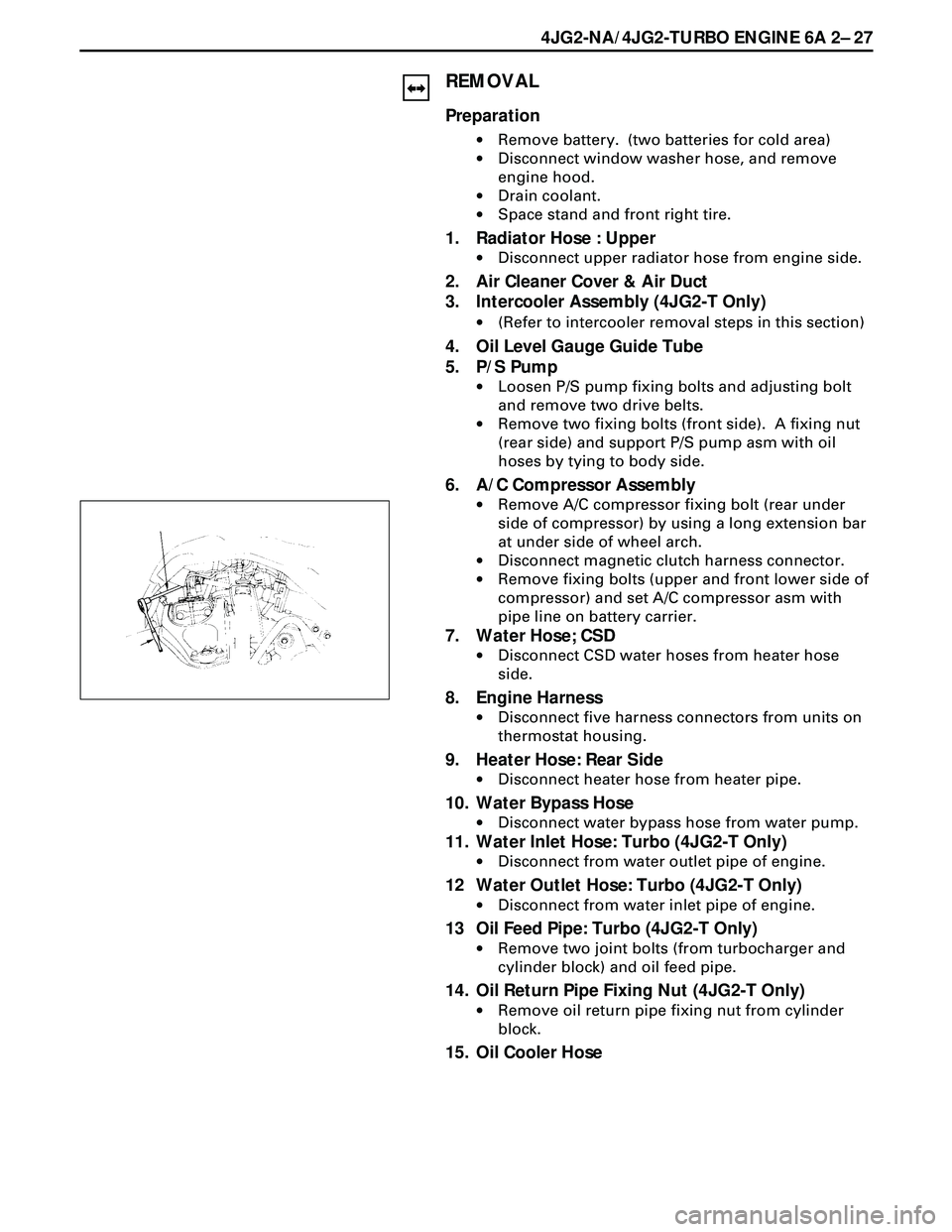
6. A/C Compressor Assembly
·Remove A/C compressor fixing bolt (rear under
side of compressor) by using a long extension bar
at under side of wheel arch.
·Disconnect magnetic clutch harness connector.
·Remove fixing bolts (upper and front lower side of
compressor) and set A/C compressor asm with
pipe line on battery carrier.
7. Water Hose; CSD
·Disconnect CSD water hoses from heater hose
side.
8. Engine Harness
·Disconnect five harness connectors from units on
thermostat housing.
9. Heater Hose: Rear Side
·Disconnect heater hose from heater pipe.
10. Water Bypass Hose
·Disconnect water bypass hose from water pump.
11. Water Inlet Hose: Turbo (4JG2-T Only)
·Disconnect from water outlet pipe of engine.
12 Water Outlet Hose: Turbo (4JG2-T Only)
·Disconnect from water inlet pipe of engine.
13 Oil Feed Pipe: Turbo (4JG2-T Only)
·Remove two joint bolts (from turbocharger and
cylinder block) and oil feed pipe.
14. Oil Return Pipe Fixing Nut (4JG2-T Only)
·Remove oil return pipe fixing nut from cylinder
block.
15. Oil Cooler Hose
Page 1664 of 3573
6B Ð 10 ENGINE COOLING
Radiator Core
·Deformed radiator fins could reduce radiation effects,
resulting in overheat. Straighten the fins. In such a
case, take care not to damage the fin roots.
·Remove dust and other foreign materials.
Flushing the Radiator
·Wash the inside of radiator and the coolant passage
with water and neutral detergent. Remove all scales
and rust.
Checking for Coolant Leakage
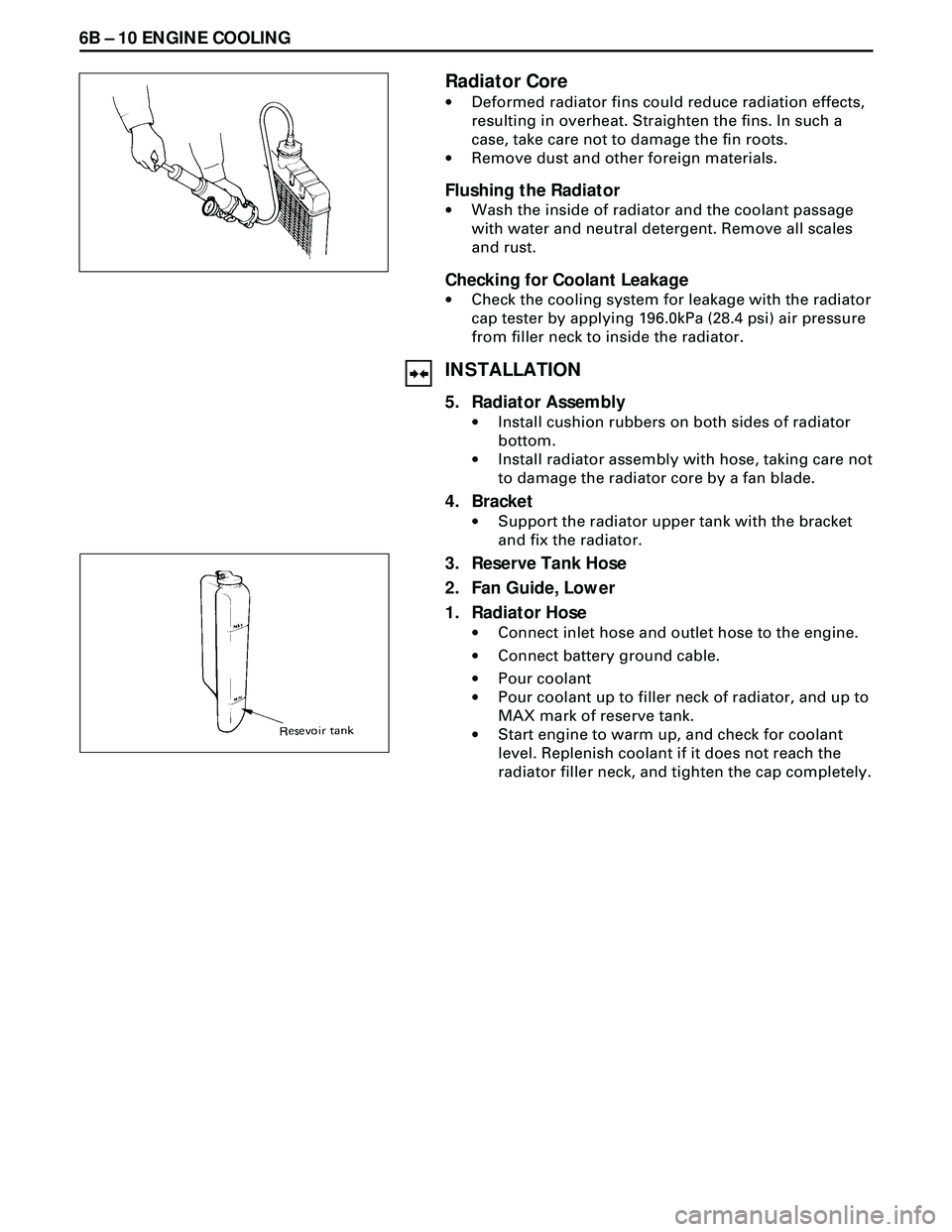
·Check the cooling system for leakage with the radiator
cap tester by applying 196.0kPa (28.4 psi) air pressure
from filler neck to inside the radiator.
INSTALLATION
5. Radiator Assembly
·Install cushion rubbers on both sides of radiator
bottom.
·Install radiator assembly with hose, taking care not
to damage the radiator core by a fan blade.
4. Bracket
·Support the radiator upper tank with the bracket
and fix the radiator.
3. Reserve Tank Hose
2. Fan Guide, Lower
1. Radiator Hose
·Connect inlet hose and outlet hose to the engine.
·Connect battery ground cable.
·Pour coolant
·Pour coolant up to filler neck of radiator, and up to
MAX mark of reserve tank.
·Start engine to warm up, and check for coolant
level. Replenish coolant if it does not reach the
radiator filler neck, and tighten the cap completely.
Page 1743 of 3573
6A – 10 ENGINE MECHANICAL
8. Check the engine oil level and replenish to the
specified level if required.
9. Start the engine and check for oil leakage from the
main oil filter.
FUEL SYSTEM
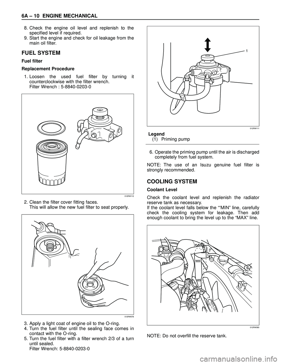
Fuel filter
Replacement Procedure
1. Loosen the used fuel filter by turning it
counterclockwise with the filter wrench.
Filter Wrench : 5-8840-0203-0
2. Clean the filter cover fitting faces.
This will allow the new fuel filter to seat properly.
3. Apply a light coat of engine oil to the O-ring.
4. Turn the fuel filter until the sealing face comes in
contact with the O-ring.
5. Turn the fuel filter with a filter wrench 2/3 of a turn
until sealed.
Filter Wrench: 5-8840-0203-0Legend
(1) Priming pump
6. Operate the priming pump until the air is discharged
completely from fuel system.
NOTE: The use of an Isuzu genuine fuel filter is
strongly recommended.
COOLING SYSTEM
Coolant Level
Check the coolant level and replenish the radiator
reserve tank as necessary.
If the coolant level falls below the “‘MIN” line, carefully
check the cooling system for leakage. Then add
enough coolant to bring the level up to the “MAX” line.
NOTE: Do not overfill the reserve tank.
012RW112
012RW078
1
012RW111
012RW080
Page 1744 of 3573
ENGINE MECHANICAL 6A – 11
Remove the radiator filler cap only when absolutely
necessary.
Always check the coolant level when the engine is cold.
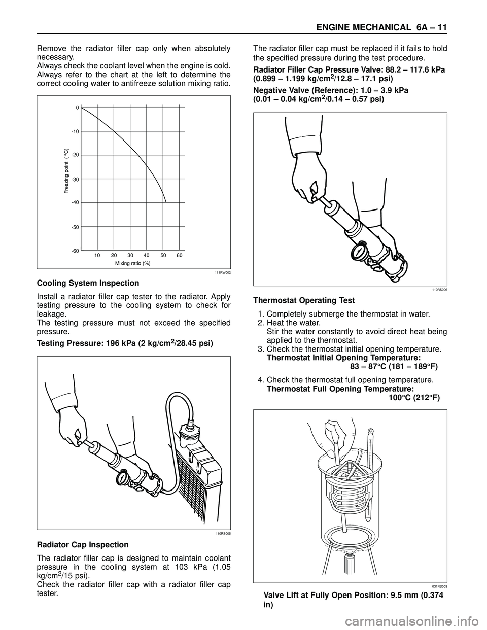
Always refer to the chart at the left to determine the
correct cooling water to antifreeze solution mixing ratio.
Cooling System Inspection
Install a radiator filler cap tester to the radiator. Apply
testing pressure to the cooling system to check for
leakage.
The testing pressure must not exceed the specified
pressure.
Testing Pressure: 196 kPa (2 kg/cm
2/28.45 psi)
Radiator Cap Inspection
The radiator filler cap is designed to maintain coolant
pressure in the cooling system at 103 kPa (1.05
kg/cm
2/15 psi).
Check the radiator filler cap with a radiator filler cap
tester.The radiator filler cap must be replaced if it fails to hold
the specified pressure during the test procedure.
Radiator Filler Cap Pressure Valve: 88.2 – 117.6 kPa
(0.899 – 1.199 kg/cm
2/12.8 – 17.1 psi)
Negative Valve (Reference): 1.0 – 3.9 kPa
(0.01 – 0.04 kg/cm
2/0.14 – 0.57 psi)
Thermostat Operating Test
1. Completely submerge the thermostat in water.
2. Heat the water.
Stir the water constantly to avoid direct heat being
applied to the thermostat.
3. Check the thermostat initial opening temperature.
Thermostat Initial Opening Temperature:
83 – 87°C (181 – 189°F)
4. Check the thermostat full opening temperature.
Thermostat Full Opening Temperature:
100°C (212°F)
Valve Lift at Fully Open Position: 9.5 mm (0.374
in)0
-10
-20
-30
-40
-50
-60
10 20 30
Mixing ratio (%)
Freezing point ( °C)
40 50 60
111RW002
110RS005
110RS006
031RS003
Page 1768 of 3573
ENGINE MECHANICAL 6A – 35
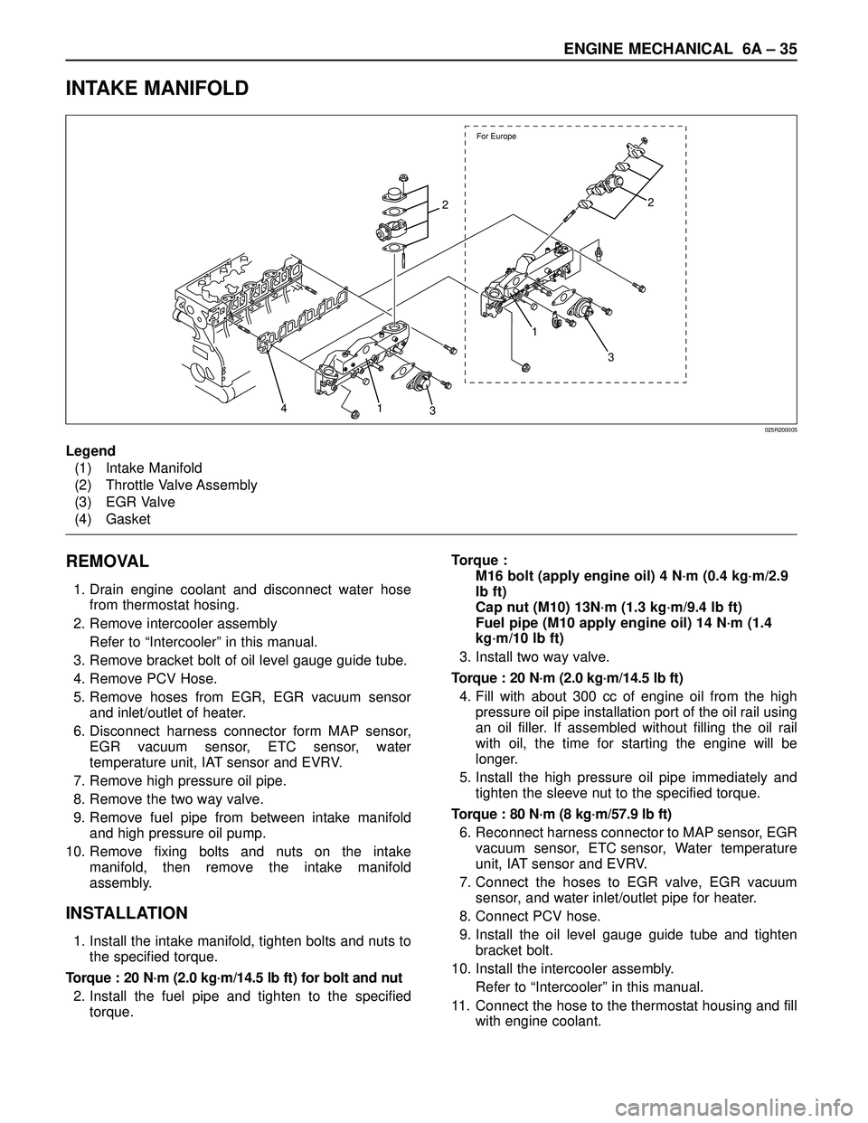
INTAKE MANIFOLD
REMOVAL
1. Drain engine coolant and disconnect water hose
from thermostat hosing.
2. Remove intercooler assembly
Refer to “Intercooler” in this manual.
3. Remove bracket bolt of oil level gauge guide tube.
4. Remove PCV Hose.
5. Remove hoses from EGR, EGR vacuum sensor
and inlet/outlet of heater.
6. Disconnect harness connector form MAP sensor,
EGR vacuum sensor, ETC sensor, water
temperature unit, IAT sensor and EVRV.
7. Remove high pressure oil pipe.
8. Remove the two way valve.
9. Remove fuel pipe from between intake manifold
and high pressure oil pump.
10. Remove fixing bolts and nuts on the intake
manifold, then remove the intake manifold
assembly.
INSTALLATION
1. Install the intake manifold, tighten bolts and nuts to
the specified torque.
Torque : 20 N·m (2.0 kg·m/14.5 lb ft) for bolt and nut
2. Install the fuel pipe and tighten to the specified
torque.Torque :
M16 bolt (apply engine oil) 4 N·m (0.4 kg·m/2.9
lb ft)
Cap nut (M10) 13N·m (1.3 kg·m/9.4 lb ft)
Fuel pipe (M10 apply engine oil) 14 N·m (1.4
kg·m/10 lb ft)
3. Install two way valve.
Torque : 20 N·m (2.0 kg·m/14.5 lb ft)
4. Fill with about 300 cc of engine oil from the high
pressure oil pipe installation port of the oil rail using
an oil filler. If assembled without filling the oil rail
with oil, the time for starting the engine will be
longer.
5. Install the high pressure oil pipe immediately and
tighten the sleeve nut to the specified torque.
Torque : 80 N·m (8 kg·m/57.9 lb ft)
6. Reconnect harness connector to MAP sensor, EGR
vacuum sensor, ETC sensor, Water temperature
unit, IAT sensor and EVRV.
7. Connect the hoses to EGR valve, EGR vacuum
sensor, and water inlet/outlet pipe for heater.
8. Connect PCV hose.
9. Install the oil level gauge guide tube and tighten
bracket bolt.
10. Install the intercooler assembly.
Refer to “Intercooler” in this manual.
11. Connect the hose to the thermostat housing and fill
with engine coolant.
For Europe
2
1
3
3 1 42
025R200005
Legend
(1) Intake Manifold
(2) Throttle Valve Assembly
(3) EGR Valve
(4) Gasket
Page 1777 of 3573
6A – 44 ENGINE MECHANICAL
REMOVAL
1. Disconnect battery ground cable.
2. Drain engine coolant.
3. Remove air cleaner and air duct.
4. Remove intercooler assembly.
Refer to “Intercooler” in this manual.
5. Remove oil level gauge guide assembly.
6. Remove PCV hose.
7. Remove EGR vacuum hose.
8. Disconnect harness connector around the cylinder
head.
9. Remove A/C compressor assembly.
10. Remove A/C compressor bracket.
11. Remove generator assembly and take out fan belt.
12. Remove heat protector and remove valve
assembly.
13. Remove water hose and oil pipe from turbocharger.
14. Remove turbocharger assembly.
15. Remove water hose between thermostat and
radiator.
16. Remove cylinder head noise insulator cover.
NOTE: Do not make damage to the harness.
17. Remove high pressure pipe.
18. Remove timing belt cover.
19. Remove CMP sensor bracket.
20. Remove timing belt tensioner and remove timing
belt.
21. Remove camshaft pulley.
22. Remove front plate.
23. Remove water pipe between cylinder head and
water pump.
24. Remove fuel pipe between fuel pump and intake
manifold.
25. Remove fuel return pipe.
26. Remove intake manifold assembly.
27. Disconnect glow plug wiring and remove glow plug.
28. Remove cylinder head cover.
29. Drain oil from oil rail.
30. Disconnect injector harness connector.
31. Disconnect harness connector from oil pressure
sensor and oil temperature sensor on the oil rail.
32. Disconnect injector harness assembly.
33. Remove injector clamp.
34. Remove injector spacer (If equipped.).
35. Remove injector assembly.
36. Remove oil rail assembly.
37. Remove camshaft carrier.
38. Remove cylinder head assembly.
39. Remove cylinder gasket.
INSTALLATION
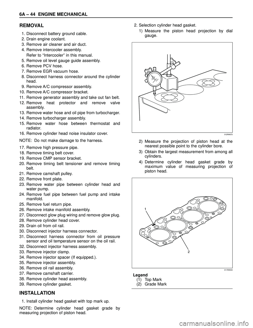
1. Install cylinder head gasket with top mark up.
NOTE: Determine cylinder head gasket grade by
measuring projection of piston head.2. Selection cylinder head gasket.
1) Measure the piston head projection by dial
gauge.
2) Measure the projection of piston head at the
nearest possible point to the cylinder bore.
3) Obtain the largest measurement from among all
cylinders.
4) Determine cylinder head gasket grade by
maximum value of measuring projection of
piston head.
Legend
(1) Top Mark
(2) Grade Mark
012RW073
2 1
011RW043