Page 1572 of 3573

6A Ð 22 ENGINE MECHANICAL
DISASSEMBLY
1. Flywheel
2. Cylinder Block Rear Plate
3. Crankcase Assembly
¥ Refer to section 6A2 ÒCrankcaseÓ.
4. Oil Pump Assembly
5. Oil Pipe
6. Strainer Assembly
7. Pump Cover
8. Driven Gear
9. Pinion Gear
10. Relief Valve
11. Drive Shaft
12. Oil Pump Body
INSPECTION AND REPAIR
Make the necessary adjustments, repairs, and part placements if excessive wear or damage is discovered
during inspection.
Body and gears
The pump assembly must be replaced if one or more of
the conditions below is discovered during inspection.
¥ Badly worn or damaged driven gear guide.
¥ Badly worn or damaged gear teeth.
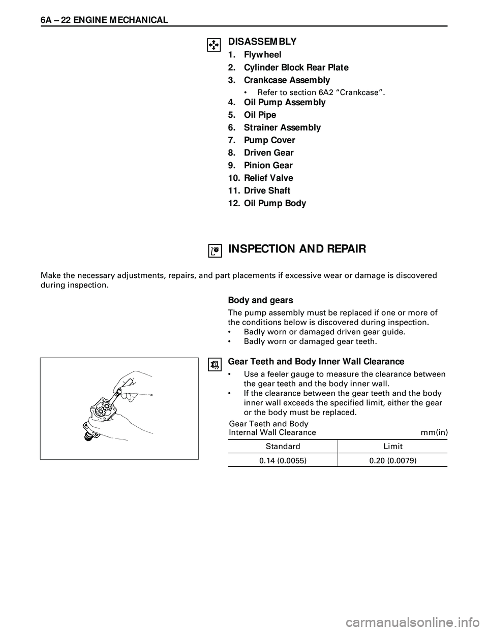
Gear Teeth and Body Inner Wall Clearance
¥ Use a feeler gauge to measure the clearance between
the gear teeth and the body inner wall.
¥ If the clearance between the gear teeth and the body
inner wall exceeds the specified limit, either the gear
or the body must be replaced.
Standard Limit
mm(in)
0.14 (0.0055) Gear Teeth and Body
Internal Wall Clearance
0.20 (0.0079)
Page 1574 of 3573
6A Ð 24 ENGINE MECHANICAL
4. Oil Pump Assembly
¥ Apply molybdenum mixed engine oil to drive
gear of camshaft and driven gear of oil pump.
¥ Tighten the oil pump fixing bolt to the specified
torque
3. Crankcase Assembly
¥ Refer to Section 6A2 ÒCrankcaseÓ.
2. Cylinder Block Rear Plate
¥ Align the rear plate with the cylinder body knock
pins. Tighten the rear plate to the specified
torque.
1. Flywheel
¥ Refer to Section 6A2 ÒCrankshaft and Main
BearingÓ.
19 (1.9/14)
N·m(kg·m/lb·ft)
82 (8.4/61)
N·m(kg·m/lb·ft)
Page 1575 of 3573
ENGINE MECHANICAL 6A Ð 25
CRANKSHAFT
DISASSEMBLY
1. Cylinder Head
·Refer to ÒCylinder headÓ in Section 6A2.
2. Camshaft Timing Gear
·Refer to ÒCamshaftÓ in Section 6A2.
3. Crankshaft Timing Gear
4. Crankshaft Front Oil Seal
5. Timing Gear Case
6. Flywheel
7. Cylinder Block Rear Plate
Page 1582 of 3573

6A Ð 32 ENGINE MECHANICAL
19 (1.9/14)N·m(kg·m/lb·ft)
5. Timing Gear Case
1) Install the timing gear case to the cylinder body.
NOTE:
Take care not to twist the front oil seal.
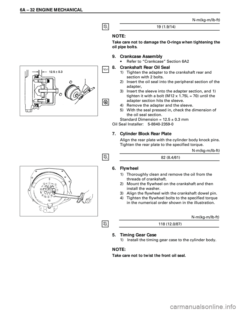
6. Flywheel
1) Thoroughly clean and remove the oil from the
threads of crankshaft.
2) Mount the flywheel on the crankshaft and then
install the washer.
3) Align the flywheel with the crankshaft dowel pin.
4) Tighten the flywheel bolts to the specified torque
in the numerical order shown in the illustration.
82 (8.4/61)N·m(kg·m/lb·ft)
NOTE:
Take care not to damage the O-rings when tightening the
oil pipe bolts.
9. Crankcase Assembly
·Refer to ÒCrankcaseÓ Section 6A2
8. Crankshaft Rear Oil Seal
1) Tighten the adapter to the crankshaft rear and
section with 2 bolts.
2) Insert the oil seal into the peripheral section of the
adapter,
3) Insert the sleeve into the adapter section, and 1)
tighten it with a bolt (M12 x 1.75L = 70) until the
adapter section hits the sleeve.
4) Remove the adapter and the sleeve.
5) With the seal pressed in, check the dimension of
the oil seal section.
Standard Dimension = 12.5 ± 0.3 mm
Oil Seal Installer: 5-8840-2359-0
7. Cylinder Block Rear Plate
Align the rear plate with the cylinder body knock pins.
Tighten the rear plate to the specified torque.
118 (12.0/87)N·m(kg·m/lb·ft)
Page 1592 of 3573
6A Ð 42 ENGINE MECHANICAL
CYLINDER BLOCK
DISASSEMBLY
1. Cylinder Head Assembly
·Refer to ÒCylinder headÓ in Section 6A2.
2. Cylinder Head Gasket
3. Flywheel
4. Cylinder Block Rear Plate
5. Crankshaft Rear Oil Seal
·With the oil seal pushed in deep, install the special
tool as shown in the illustration and remove the oil
seal.
Oil Seal Remover : 5-8840-2362-0
6. Crankcase Assembly
·Refer to ÒCrankcaseÓ in Section 6A2
7. Oil Pump Assembly
Page 1600 of 3573

6A Ð 50 ENGINE MECHANICAL
8. Camshaft Timing Gear
1) Install the camshaft timing gear to the camshaft.
The timing gear mark ("Y - Y") must be facing
outword.
2) Tighten the timing gear to the specified torque.
64 (6.5/47)N·m (kg·m/lb·ft)
7. Oil Pump Assembly
·Refer to ÔOil pumpÕ in Section 6A2.
6. Crankcase Assembly
·Refer to ÔCrankcaseÕ in Section 6A2.
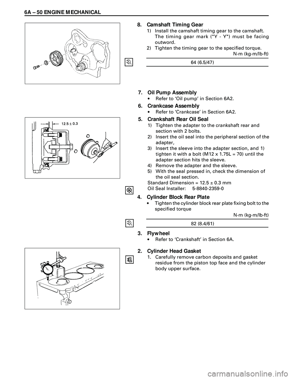
5. Crankshaft Rear Oil Seal
1) Tighten the adapter to the crankshaft rear and
section with 2 bolts.
2) Insert the oil seal into the peripheral section of the
adapter,
3) Insert the sleeve into the adapter section, and 1)
tighten it with a bolt (M12 x 1.75L = 70) until the
adapter section hits the sleeve.
4) Remove the adapter and the sleeve.
5) With the seal pressed in, check the dimension of
the oil seal section.
Standard Dimension = 12.5 ± 0.3 mm
Oil Seal Installer: 5-8840-2359-0
4. Cylinder Block Rear Plate
·Tighten the cylinder block rear plate fixing bolt to the
specified torque
82 (8.4/61)N·m (kg·m/lb·ft)
3. Flywheel
·Refer to ÔCrankshaftÕ in Section 6A.
2. Cylinder Head Gasket
1. Carefully remove carbon deposits and gasket
residue from the piston top face and the cylinder
body upper surface.
Page 1604 of 3573

6A2 Ð 2 4JG2-NA/4JG2-TURBO ENGINE
RECARD Comet V Type swirl combustion chamber which
provides superior driving performance, fuel economy and
silent combustion over a wide range of driving
conditions, is applied.
The cylinder head gasket is of laminated steel sheets.
Three grades of the gasket according to the measured
piston head projection from the cylinder block are
provided to give the engine a minimum compression
ration fluctuation.
The cylinder head fixing blots, flywheel bolts and con-
necting rod fixing bolts are tightened by the angular
Tightening Method.
The chrome plated steel dry type (Chromard) cylinder
liners provide the highest durability.
Auto-thermatic pistons having steel struts with 0.7 mm
offset from the piston pin center line, ate applied to
reduce thermal expansion and resulting engine noise
when the engine is cold.
The crankshaft bearings and connecting rod bearings are
of aluminum having a high bearing surface.
These bearing are especially sensitive to foreign material
such as metal scraps. So, it is very important that the oil
ports and other related surfaces are kept clean and free of
foreign material.
Crank shaft bearing selection for optimum bearing and
journal clearance is applied to reduce vibration and noise.
As tufftriding (Nitrizing treatment) is applied to increase
crankshaft strength, crankpins and journals should not be
reground.
An oiling jet device for piston cooling is provided in the
lubricating oil circuit from cylinder block oil gallery via a
check valve.
Take care not to damage any oiling jet when removing
and installing piston and connecting assembly.
The DFI (Double Formation Injection) Pintaux Type
injection nozzle having a sub-injection hole is applied.
This nozzle contributes to substantially minimize the
diesel knocking sound noticeable in the cold engine idling
operation.
Install the injection nozzle, directing the sub-injection hole
to the specified direction.
QOS III preheating system which features a quick-on glow
plug with thermometer control of the glowing time and
the afterglow time function, is applied.
Page 1614 of 3573
6A2Ð 12 4JG2-NA/4JG2-TURBO ENGINE
5. Air Conditioner (A/C) Compressor Assembly
·Remove A/C compressor fixng bolt (rear under
side of compressor) by using a long extension bar
at under side of wheel arch.
·Disconnect magnetic clutch harness connector.
·Removal fixing bolts (upper and front lower sides
of compressor) and set A/C compressor asm with
pipelines on battery cable.
6. Water Inlet Pipe: Turbo (4JG2-T Only)
7. Oil Feed Pipe: Turbo (4JG2-T Only)
·Remove joint bolt from turbo charger.
·Plug up oil port of turbocharger to prevent
entrance of foreign material.
8. Oil Return Pipe: Turbo (4JG2-T Only)
·Disconnect oil return pipe flange from
turbocharger.
9. Water Outlet Pipe: Turbo (4JG2-T Only)
10. Exh. Pipe: Ft (4JG2-T Only)
11. Heat Protector (4JG2-T Only)
12. Exh. Adapter (4JG2-T Only)
13. Turbocharger Assembly (4JG2-T Only)
·Remove turbocharger asm from exhaust
manifold.