Page 118 of 3573
HEATING AND VENTILATION 1A Ð 23
INSTALLATION
To install, follow the removal steps in the reverse order.
REMOVAL
1. Front console assembly
2. Lower cluster assembly
3. Instrument panel driver lower cover assembly
4. Meter cluster assembly
·Refer to Section 10 ÒBODYÓ for INSTRUMENT
PANEL ASSEMBLY removal procedure.
5. Center vent
·Remove screws and the center vent from center
cluster while prying up the center vent catch
portions.
6. Side vent
·Remove screws and the side vent from center
cluster while prying up the side vent catch
portions.
Page 119 of 3573
1A Ð 24 HEATING AND VENTILATION
Removal Steps
1. Center console assembly
2. Lower cluster assembly
3. Glove box
4. Instrument panel passenger lower
cover assembly
5. Instrument panel driver lower cover
assembly
6. Meter cluster assembly
7. Attaching screws
8. Fan switch and air conditioning switch
connector
9. Control lever assembly
10. Control cable
CONTROL LEVER ASSEMBLY AND/OR CONTROL CABLES
6
1
5
2
10
7
7
88
910
To Mode control linkTo Temp control linkTo Blower assembly
4
3
Installation Steps
To install, follow the removal steps in
the reverse order.
This illustration is based on LHD
Page 120 of 3573
HEATING AND VENTILATION 1A Ð 25
REMOVAL
Preparation:
Disconnect the battery ground cable
1. Front console assembly
2. Lower cluster assembly
3. Glove box
4. Instrument panel passenger lower cover
5. Instrument panel driver lower cover
6. Meter cluster assembly
Refer to Section 10 ÒBODYÓ for INSTRUMENT PANEL
ASSEMBLY removal procedure.
7. Attaching Screws
Remove the 4 attaching screws and disconnect the
control lever cables at heater unit and blower
assembly.
8. Fan Switch and A/C Switch Connector
Pull the control lever assembly out and disconnect
the connectors.
9. Control Lever Assembly
10. Control Cable
Page 123 of 3573
1A Ð 28 HEATING AND VENTILATION
5
7
6To Blower unit
To Heater unit
34
12
Removal Steps
1. Front console assembly
2. Lower cluster assembly
3. Glove box
4. Instrument panel passenger
lower cover
5. Resistor connector
6. Duct (Heater only)
7. Resistor
Installation Steps
To install, follow the removal steps in the
reverse order.
RESISTOR
This illustration is based on RHD
Page 124 of 3573
HEATING AND VENTILATION 1A Ð 29
REMOVAL
Preparation:
Disconnect the battery ground cable
1. Front console assembly
2. Lower cluster assembly
3. Glove box
4. Instrument panel passenger lower cover
Refer to Section 10 ÒBODYÓ for INSTRUMENT PANEL
ASSEMBLY removal procedure.
5. Resistor connector
6. Duct (Heater only)
7. Resistor
INSTALLATION
To install, follow the removal steps in the reverse order.
Page 125 of 3573
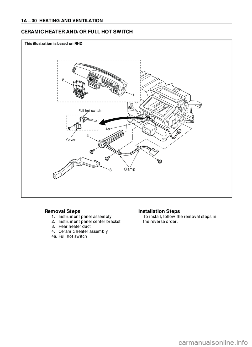
1A Ð 30 HEATING AND VENTILATION
4
4a
3
Full hot switch
Cover
Clamp
22
0
25
30AUTOA
/
CO
F
FAUTOLOHI
1
�y��
Removal Steps
1. Instrument panel assembly
2. Instrument panel center bracket
3. Rear heater duct
4. Ceramic heater assembly
4a. Full hot switch
CERAMIC HEATER AND/OR FULL HOT SWITCH
Installation Steps
To install, follow the removal steps in
the reverse order.
This illustration is based on RHD
Page 126 of 3573
HEATING AND VENTILATION 1A Ð 31
REMOVAL
Preparation:
Disconnect the battery ground cable
1. Instrument panel assembly
Refer to Section 10 ÒBODYÓ for ÒINSTRUMENT
PANEL ASSEMBLYÓ removal procedure.
2. Instrument panel center bracket
Refer to Section 10 ÒCROSS BEAM ASSEMBLYÓ
removal procedure.
3. Rear heater duct
4. Ceramic heater
1) Disconnect the connector and remove the heater
fixing screw and heater harness fixing clamps.
2) Pull the ceramic heater out from heater unit.
4a. Full hot switch
Disconnect the switch connector and remove the
switch fixing screw and switch harness fixing clamp.
INSTALLATION
To install, follow the removal steps in the reverse order,
noting the following points.
1. The installation should be made with care so that
there is continuity between the switch side connector
terminals when the knob is set to the ÒFull HotÓ
position.
2. Be sure to handle the EGR and the ABS control unit
with care to avoid the disengagement of connectors.
Page 168 of 3573
1B Ð 42 AIR CONDITIONING
Removal Steps
1. Front console assembly
2. Lower cluster assembly
3. Glove box
4. Instrument panel passenger
lower cover assembly
5. Passenger knee bolster
reinforcement assembly
6. Resistor and electronic
thermostat connector
7. Drain hose
8. Refrigerant line
9. Evaporator assembly
Installation Steps
To install, follow the removal steps in the
reverse order.
EVAPORATOR ASSEMBLY
1 2
3
456
7
8 9 This illustration is based on LHD
Electronic thermostat
Resistor
850RW00001