1998 ISUZU TROOPER driveline
[x] Cancel search: drivelinePage 722 of 3573

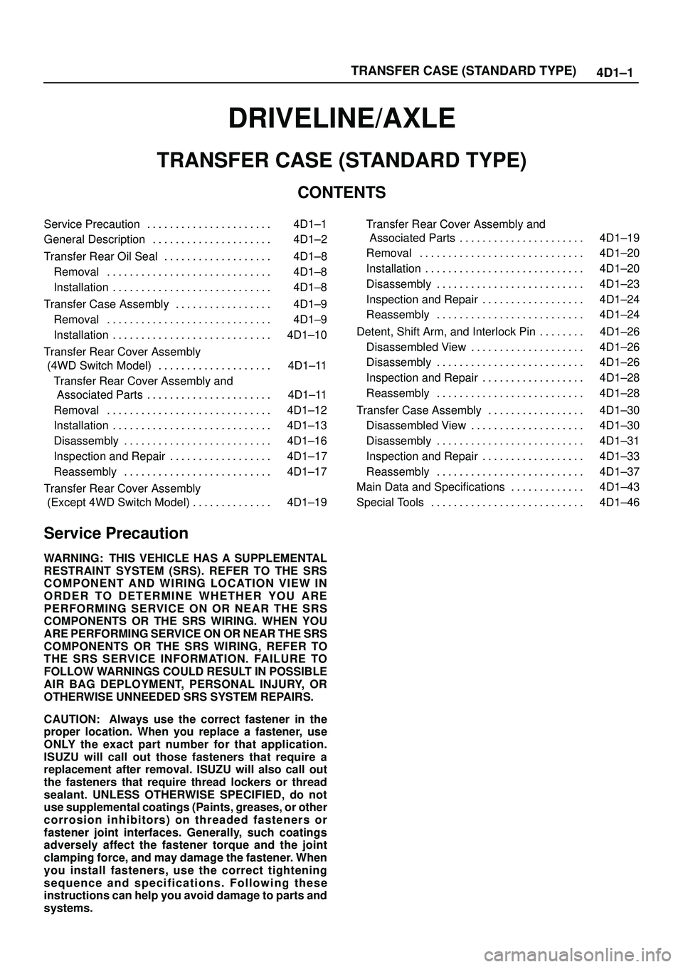
TRANSFER CASE (STANDARD TYPE)
4D1±1
DRIVELINE/AXLE
TRANSFER CASE (STANDARD TYPE)
CONTENTS
Service Precaution 4D1±1. . . . . . . . . . . . . . . . . . . . . .
General Description 4D1±2. . . . . . . . . . . . . . . . . . . . .
Transfer Rear Oil Seal 4D1±8. . . . . . . . . . . . . . . . . . .
Removal 4D1±8. . . . . . . . . . . . . . . . . . . . . . . . . . . . .
Installation 4D1±8. . . . . . . . . . . . . . . . . . . . . . . . . . . .
Transfer Case Assembly 4D1±9. . . . . . . . . . . . . . . . .
Removal 4D1±9. . . . . . . . . . . . . . . . . . . . . . . . . . . . .
Installation 4D1±10. . . . . . . . . . . . . . . . . . . . . . . . . . . .
Transfer Rear Cover Assembly
(4WD Switch Model) 4D1±11. . . . . . . . . . . . . . . . . . . .
Transfer Rear Cover Assembly and
Associated Parts 4D1±11. . . . . . . . . . . . . . . . . . . . . .
Removal 4D1±12. . . . . . . . . . . . . . . . . . . . . . . . . . . . .
Installation 4D1±13. . . . . . . . . . . . . . . . . . . . . . . . . . . .
Disassembly 4D1±16. . . . . . . . . . . . . . . . . . . . . . . . . .
Inspection and Repair 4D1±17. . . . . . . . . . . . . . . . . .
Reassembly 4D1±17. . . . . . . . . . . . . . . . . . . . . . . . . .
Transfer Rear Cover Assembly
(Except 4WD Switch Model) 4D1±19. . . . . . . . . . . . . . Transfer Rear Cover Assembly and
Associated Parts 4D1±19. . . . . . . . . . . . . . . . . . . . . .
Removal 4D1±20. . . . . . . . . . . . . . . . . . . . . . . . . . . . .
Installation 4D1±20. . . . . . . . . . . . . . . . . . . . . . . . . . . .
Disassembly 4D1±23. . . . . . . . . . . . . . . . . . . . . . . . . .
Inspection and Repair 4D1±24. . . . . . . . . . . . . . . . . .
Reassembly 4D1±24. . . . . . . . . . . . . . . . . . . . . . . . . .
Detent, Shift Arm, and Interlock Pin 4D1±26. . . . . . . .
Disassembled View 4D1±26. . . . . . . . . . . . . . . . . . . .
Disassembly 4D1±26. . . . . . . . . . . . . . . . . . . . . . . . . .
Inspection and Repair 4D1±28. . . . . . . . . . . . . . . . . .
Reassembly 4D1±28. . . . . . . . . . . . . . . . . . . . . . . . . .
Transfer Case Assembly 4D1±30. . . . . . . . . . . . . . . . .
Disassembled View 4D1±30. . . . . . . . . . . . . . . . . . . .
Disassembly 4D1±31. . . . . . . . . . . . . . . . . . . . . . . . . .
Inspection and Repair 4D1±33. . . . . . . . . . . . . . . . . .
Reassembly 4D1±37. . . . . . . . . . . . . . . . . . . . . . . . . .
Main Data and Specifications 4D1±43. . . . . . . . . . . . .
Special Tools 4D1±46. . . . . . . . . . . . . . . . . . . . . . . . . . .
Service Precaution
WARNING: THIS VEHICLE HAS A SUPPLEMENTAL
RESTRAINT SYSTEM (SRS). REFER TO THE SRS
COMPONENT AND WIRING LOCATION VIEW IN
ORDER TO DETERMINE WHETHER YOU ARE
PERFORMING SERVICE ON OR NEAR THE SRS
COMPONENTS OR THE SRS WIRING. WHEN YOU
ARE PERFORMING SERVICE ON OR NEAR THE SRS
COMPONENTS OR THE SRS WIRING, REFER TO
THE SRS SERVICE INFORMATION. FAILURE TO
FOLLOW WARNINGS COULD RESULT IN POSSIBLE
AIR BAG DEPLOYMENT, PERSONAL INJURY, OR
OTHERWISE UNNEEDED SRS SYSTEM REPAIRS.
CAUTION: Always use the correct fastener in the
proper location. When you replace a fastener, use
ONLY the exact part number for that application.
ISUZU will call out those fasteners that require a
replacement after removal. ISUZU will also call out
the fasteners that require thread lockers or thread
sealant. UNLESS OTHERWISE SPECIFIED, do not
use supplemental coatings (Paints, greases, or other
corrosion inhibitors) on threaded fasteners or
fastener joint interfaces. Generally, such coatings
adversely affect the fastener torque and the joint
clamping force, and may damage the fastener. When
you install fasteners, use the correct tightening
sequence and specifications. Following these
instructions can help you avoid damage to parts and
systems.
Page 768 of 3573

4D2±1 TRANSFER CASE (TOD)
DRIVELINE/AXLE
TRANSFER CASE (TOD)
CONTENTS
Service Precaution 4D2±1. . . . . . . . . . . . . . . . . . . . . .
Transfer Case Assembly 4D2±2. . . . . . . . . . . . . . . . .
Removal 4D2±2. . . . . . . . . . . . . . . . . . . . . . . . . . . . .
Installation 4D2±3. . . . . . . . . . . . . . . . . . . . . . . . . . . .
Transfer Rear Oil Seal 4D2±5. . . . . . . . . . . . . . . . . . .
Transfer Rear Oil Seal and Associated
Parts 4D2±5. . . . . . . . . . . . . . . . . . . . . . . . . . . . . . . .
Removal 4D2±5. . . . . . . . . . . . . . . . . . . . . . . . . . . . .
Installation 4D2±5. . . . . . . . . . . . . . . . . . . . . . . . . . . .
TOD ECU 4D2±7. . . . . . . . . . . . . . . . . . . . . . . . . . . . . .
Removal 4D2±7. . . . . . . . . . . . . . . . . . . . . . . . . . . . .
Installation 4D2±7. . . . . . . . . . . . . . . . . . . . . . . . . . . .
Unit Repair 4D2±8. . . . . . . . . . . . . . . . . . . . . . . . . . . . .
Inspection 4D2±8. . . . . . . . . . . . . . . . . . . . . . . . . . . .
Transfer Case 4D2±9. . . . . . . . . . . . . . . . . . . . . . . . . .
Disassembled View 4D2±9. . . . . . . . . . . . . . . . . . . .
Disassembly 4D2±9. . . . . . . . . . . . . . . . . . . . . . . . . .
Reassembly 4D2±10. . . . . . . . . . . . . . . . . . . . . . . . . .
Transfer Cover Assembly 4D2±12. . . . . . . . . . . . . . . .
Disassembled View 4D2±12. . . . . . . . . . . . . . . . . . . .
Disassembly 4D2±12. . . . . . . . . . . . . . . . . . . . . . . . . .
Reassembly 4D2±14. . . . . . . . . . . . . . . . . . . . . . . . . .
Transfer Case Assembly Clutch Pack and
Clutch Cam 4D2±16. . . . . . . . . . . . . . . . . . . . . . . . . . . .
Disassembled View 4D2±16. . . . . . . . . . . . . . . . . . . . Disassembly 4D2±16. . . . . . . . . . . . . . . . . . . . . . . . . .
Sprocket and Mechanical Lock 4D2±18. . . . . . . . . . . .
Disassembled View 4D2±18. . . . . . . . . . . . . . . . . . . .
Disassembly 4D2±18. . . . . . . . . . . . . . . . . . . . . . . . . .
Output Shafts and Shift Control Shaft 4D2±20. . . . . .
Disassembled View 4D2±20. . . . . . . . . . . . . . . . . . . .
Disassembly 4D2±21. . . . . . . . . . . . . . . . . . . . . . . . . .
Transfer Case 4D2±23. . . . . . . . . . . . . . . . . . . . . . . . . .
Disassembled View 4D2±23. . . . . . . . . . . . . . . . . . . .
Disassembly 4D2±24. . . . . . . . . . . . . . . . . . . . . . . . . .
Inspection and Repair 4D2±26. . . . . . . . . . . . . . . . . .
Transfer Case 4D2±30. . . . . . . . . . . . . . . . . . . . . . . . . .
Disassembled View 4D2±30. . . . . . . . . . . . . . . . . . . .
Reassembly 4D2±30. . . . . . . . . . . . . . . . . . . . . . . . . .
Output Shafts and Shift Control Shaft 4D2±34. . . . . .
Disassembled View 4D2±34. . . . . . . . . . . . . . . . . . . .
Reassembly 4D2±34. . . . . . . . . . . . . . . . . . . . . . . . . .
Sprocket and Mechanical Lock 4D2±37. . . . . . . . . . . .
Disassembled View 4D2±37. . . . . . . . . . . . . . . . . . . .
Reassembly 4D2±37. . . . . . . . . . . . . . . . . . . . . . . . . .
Clutch Pack and Clutch Cam 4D2±39. . . . . . . . . . . . .
Disassembled View 4D2±39. . . . . . . . . . . . . . . . . . . .
Reassembly 4D2±39. . . . . . . . . . . . . . . . . . . . . . . . . .
Main Data and Specifications 4D2±41. . . . . . . . . . . . .
Special Tools 4D2±43. . . . . . . . . . . . . . . . . . . . . . . . . . .
Service Precaution
WARNING: I F S O E Q U IPPED WITH A
SUPPLEMENTAL RESTRAINT SYSTEM (SRS),
REFER TO THE SRS COMPONENT AND WIRING
LOCATION VIEW IN ORDER TO DETERMINE
WHETHER YOU ARE PERFORMING SERVICE ON OR
NEAR THE SRS COMPONENTS OR THE SRS
WIRING. WHEN YOU ARE PERFORMING SERVICE
ON OR NEAR THE SRS COMPONENTS OR THE SRS
WIRING, REFER TO THE SRS SERVICE
INFORMATION. FAILURE TO FOLLOW WARNINGS
COULD RESULT IN POSSIBLE AIR BAG
DEPLOYMENT, PERSONAL INJURY, OR
OTHERWISE UNNEEDED SRS SYSTEM REPAIRS.CAUTION: Always use the correct fastener in the
proper location. When you replace a fastener, use
ONLY the exact part number for that application.
ISUZU will call out those fasteners that require a
replacement after removal. ISUZU will also call out
the fasteners that require thread lockers or thread
sealant. UNLESS OTHERWISE SPECIFIED, do not
use supplemental coatings (Paints, greases, or other
corrosion inhibitors) on threaded fasteners or
fastener joint interfaces. Generally, such coatings
adversely affect the fastener torque and the joint
clamping force, and may damage the fastener. When
you install fasteners, use the correct tightening
sequence and specifications. Following these
instructions can help you avoid damage to parts and
systems.
Page 893 of 3573

POWER ASSISTED BRAKE SYSTEM 5C – 15
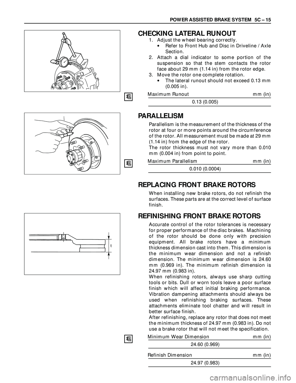
CHECKING LATERAL RUNOUT
1. Adjust the wheel bearing correctly.
•Refer to Front Hub and Disc in Driveline / Axle
Section.
2. Attach a dial indicator to some portion of the
suspension so that the stem contacts the rotor
face about 29 mm (1.14 in) from the rotor edge.
3. Move the rotor one complete rotation.
•The lateral runout should not exceed 0.13 mm
(0.005 in).
Maximum Runout mm (in)
0.13 (0.005)
PARALLELISM
Parallelism is the measurement of the thickness of the
rotor at four or more points around the circumference
of the rotor. All measurement must be made at 29 mm
(1.14 in) from the edge of the rotor.
The rotor thickness must not vary more than 0.010
mm (0.004 in) from point to point.
Maximum Parallelism mm (in)
0.010 (0.0004)
REPLACING FRONT BRAKE ROTORS
When installing new brake rotors, do not refinish the
surfaces. These parts are at the correct level of surface
finish.
REFINISHING FRONT BRAKE ROTORS
Accurate control of the rotor tolerances is necessary
for proper performance of the disc brakes. Machining
of the rotor should be done only with precision
equipment. All brake rotors have a minimum
thickness dimension cast into them. This dimension is
the minimum wear dimension and not a refinish
dimension. The minimum wear dimension is 24.60
mm (0.969 in). The minimum refinish dimension is
24.97 mm (0.983 in).
When refinishing rotors, always use sharp cutting
tools or bits. Dull or worn tools leave a poor surface
finish which will affect initial braking performance.
Vibration dampening attachments should always be
used when refinishing braking surfaces. These
attachments eliminate tool chatter and will result in
better surface finish.
After refinishing, replace any rotor that does not meet
the minimum thickness of 24.97 mm (0.983 in). Do not
use a brake rotor that will not meet the specification.
Minimum Wear Dimension mm (in)
24.60 (0.969)
Refinish Dimension mm (in)
24.97 (0.983)
t
Page 3564 of 3573

PAGE BACK PAGE NEXT
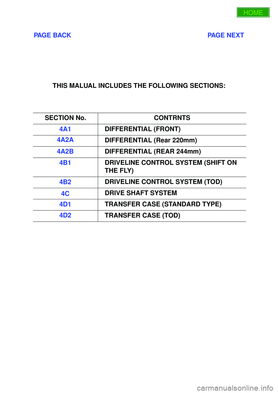
THIS MALUAL INCLUDES THE FOLLOWING SECTIONS:
SECTION No. CONTRNTS
4A1 DIFFERENTIAL (FRONT)
4A2A DIFFERENTIAL (Rear 220mm)
4A2B DIFFERENTIAL (REAR 244mm)
4B1 DRIVELINE CONTROL SYSTEM (SHIFT ON
THE FLY)
4B2 DRIVELINE CONTROL SYSTEM (TOD)
4C DRIVE SHAFT SYSTEM
4D1 TRANSFER CASE (STANDARD TYPE)
4D2 TRANSFER CASE (TOD)