Page 1085 of 1681
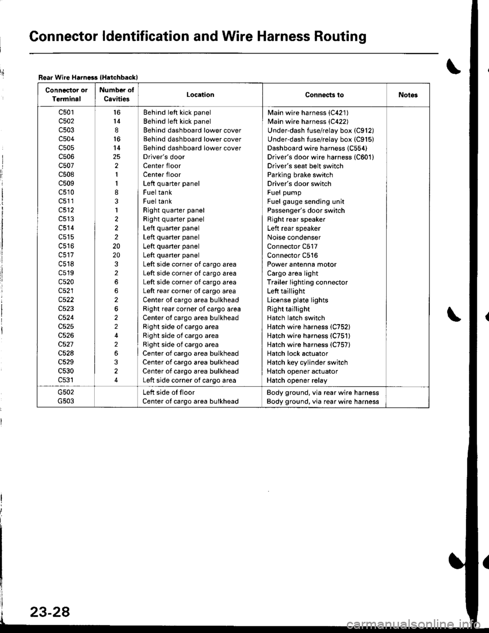
Gonnector ldentification and Wire Harness Routing
Rear Wire Harngss {Hatchbackl
Connector or
Terminal
Number of
C8vitiesLocationConnec{s toNotos
c501
c502
c504
c505
cs06
c507
c508
c509
c510
c51 1
c512
c513
c514
c515
uc to
c518
c519
c520
c522
c524
c528
c529
c530
c531
l6
14
8
16
14
2
1
I
8
3
1
2
2
2
20
20
2
2
6
2
2
2
3
4
Behind left kick panel
Behind left kick panel
Behind dashboard lower cover
Behind dashboard lower cover
Behind dashboard lower cover
Driver's door
Center floor
Center floor
Left quarter panel
Fuel tank
Fuel tank
Right quarter panel
Right quarter panel
Left quarter panel
Left quarter panel
Left quaner panel
Left quarter panel
Left side corner of cargo area
Left side corner of cargo area
Left side corner of cargo area
Left rear corner of cargo area
Center of cargo area bulkhead
Right rear corner of cargo area
Center of cargo area bulkhead
Right side of cargo area
Right side of cargo area
Right side of cargo area
Center of cargo area bulkhead
Center of cargo area bulkhead
Center of cargo area bulkhead
Left side corner of cargo area
Main wire harness {C421)
Main wire harness {C422)
Underdash fuse/relay box (C912)
Underdash fuse/relay box (C915)
Dashboard wire harness (C554)
Driver's doo. wire harness (C601)
Driver's seat belt switch
Parking brake switch
Driver's door switch
Fuel pump
Fuel gauge sending unit
Passenger's door switch
Right rear speaker
Left rear speaker
Noise condenser
Connector C517
Connector C516
Power antenna motor
Cargo area light
Trailer lighting connector
Left taillight
License plate lights
Right taillight
Hatch latch switch
Hatch wire harness (C752)
Hatch wire harness (C751)
Hatch wire harness (C757)
Hatch lock actuator
Hatch key cylinder switch
Hatch opener actuator
Hatch opener relay
Left side of floor
Center of cargo area bulkhead
Body ground, via rear wire harness
Body ground. via rear wire harness
riI
Page 1087 of 1681
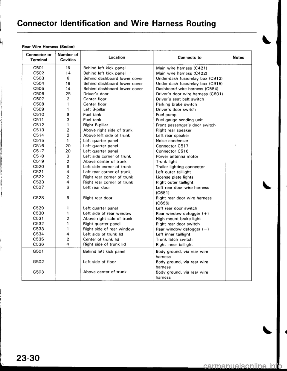
Connector ldentification and Wire Harness Routing
Connector or
Terminal
Numbel of
CavitiesLocationConnects toNotes
c501
c502
c503
c504
c505
c506
c507
c508
c509
c5l0
c511
c512
c513
c514
c515
c517
c518
c519
c520
c521
c522
c523
c527
c528
c529
c530
c531
c532
c533
c534
c535
cs36
14
8
14
2
1
1
8
3
1
2
2
1
20
20
3
2
6
4
2
4
6
6
1
1
2
1
1
4
2
4
Behind left kick panel
Behind left kick panel
Behind dashboard lower cover
Behind dashboard lower cover
Behind dashboard lower cover
Driver's door
Center floor
Center floor
Left B-pillar
Fuel tank
Fuel tank
Right B pillar
Above right side of trunk
Above left side of trunk
Left quarter panel| .{+ ^',rrrar ^rnal
Left quarter panel
Left side corner of trunk
Above center of trunk
Left side corner of trunk
Left rear corner of trunk
Right rear corner o{ trunk
Right rear corner ot trunk
Lelt rear door
Right rear door
Left quarter panel
Left side of rear window
Above right side of trunk
Right quarter panel
Right side of rear window
Left side of trunk lid
Center of trunk lid
Right side of trunk lid
lvlain wire harness (C421 )
lvlain wire harness (C422)
Underdash fuse/relay box (C912)
Under dash fuse/relay box (C915)
Dashboard wire harness (C554)
Driver's door wire harness (C6Ol)
Driver's seat belt switch
Parking brake switch
Driver's door switch
Fuel pump
Fuel gauge sending unit
Front passenger's door switch
Right rear speaker
Left rear speaker
Noise condenser
Connector C517
Connector C516
Power antenna motor
Trunk light
Trailer lighting connector
Left outer taillight
License plate lights
Right outer taillight
Lett rear door wire harness
(c651)
Right rear door wire harness
1C656)
Left rear door switch
Rear window defogger {+ )
High mount brake light
Right rear door switch
Rear window detogger (- I
Left inner taillight
Trunk latch switch
Right inner taillight
G501
G502
G503
Behind left kick panel
Left side of tloor
Above center of trunk
Body ground, via rear wire
harness
Body ground, via rear wire
harness
Body ground, via rear wire
harness
Rear Wire Hamess {Sedan}
I
ri
I
i
I
li
!
Page 1122 of 1681
I "tl
III
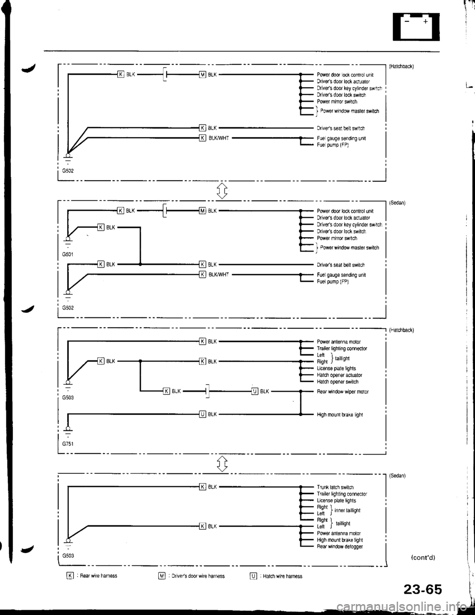
J- - - - --------- l (Haldlback)
Power door oci contro unrt IDriveas door lockaclualof I;Dtlver's door key cylinder swrtclrDfveas door lock swilch
BLKMHT ---1-
I Power window masler swildl)
Dr veis seal belt swilch
Fue gauge sending lnilFue plmp (FP)
ri:
----------l (sedan)
Power dooa lock conlrol unil IDriveas door lock aclualor I
BLKWHT-
Drlver's door key cylinder swllchDrlve/s door lock swilch
I Power window masler swilch)
Dive. s seal beit swilch
Foelgaee sending unitFuelpump (FP)
i Gso2
_ _ _--_______.] {Halchback)
r- || | F T6iler tiqhxng conneclor I
lil i ,",rror,'nqfi JLicense plale lighlsHalci opener aotualorHalci opener swilch
Rear window wiper molor
High mounl hake ighl
otw ^ -n1
t-
l_:1' ^r;-"-1 7_1;.^G503
Trunk lalch swildlTf ailer light ng conneclorLicense plate lighlsRiohl I�L; J Inner larqnr
Riohl I� .Le-ft J raflqnl
High mounl brake lighlRea. window d€logger
I
""*'�
I
(cont'd)
B : R6arwire hamessM : Dver's doorwire harness@ Hatchwire harness
:
G503
23-65
Page 1156 of 1681
)
)
Charging System
Component Locationlndex
CHARGING SYSTEM LIGHT(ln the gauge assembly)Test, pages 23-102,103Bulb Locations, page 23-122
UNDER-HOOD FUSE/RELAY BOX(USA: HAS bUiIt-iN ELECTRICALLOAD DETECTOR (ELD) UNIT}Troubleshooting of ELD, secrion 11
BATTERYTest,
ALTERNATOR BELTInsp€ction and Adiustment, page 23_115ALTERNATORTroubleshooting, page 23'102Alternator/FegulatorTosl, pages 23-105,'106Replacement, page 107Overhaul, page 23-108
23-99
.t-
Page 1164 of 1681
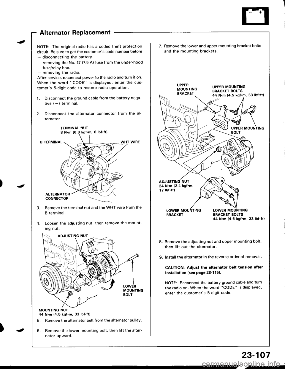
Alternator Replacement
)
t
-
NOTE: The original radio has a coded theft protection
circuit. Be sure to get the customer's code number before
- disconnecting the battery.
- removing the No. 47 (7.5 A) fuse from the under-hood
fuse/relay box.
removing the radio.
After service, reconnect power to the radio and turn it on.
When the word "CODE" is displayed, enter the cus
tomer's s-digit code to restore radio operation.
1. Disconnect the ground cable from the battery nega-
tive (- ) terminal.
2. Disconnect the alternator connector from the al-
lernalor,
TERMINAL NUT8 N,m (O.8 kgf'm, 6 lbl'ft)
B TERMINAL
ALTERNATORCONNECTOR
Remove the terminal nut and the WHT wire from the
B terminal.
Loosen the adjusting nut, then remove the mount-
Ing nut.
MOUNTINGBOLT
MOUNTING NUT44 N.m (4.5 kgf.m.33 lbt.ftl
5. Remove the alternator belt from the alternator pulley.
6. Remove the lower mounting bolt, then lilt the alter-
naror upwaro.
3.
{--,
7.Remove the lower and upper mounting bracket bolts
and the mounting brackets.
BRACKET BOLTSil4 N.m {4.5 kgl.m, 33 lbt.ft)
8. Remove the adiusting nut and upper mounting bolt,
then lift out the alternator.
9. lnstallthe alternator in the reverse order of removal.
CAUTION: Adiust the alternator belt tension aftsr
installation lseo page 23-1151.
NOTE: Reconnect the battery ground cable and turn
the radio on. When the word "CODE" is displayed,
enter the customer's s-digit code.
BRACKET
UPPER MOUNTINGBRACKET EOLTS44 N.m {4.5 kgl.m, 33 lbl'ft)
24 N.m (2.4 kgf.m,17 rbf.ftl
b-h..K
) I
23-107
-
,-
Page 1172 of 1681
)
t
J
Altelnator ttelr Inspecuon ano Aol
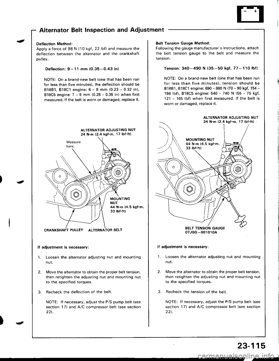
Detlection Method:
Apply a force ol 98 N (1 0 ksl, 22 lbl) and measure the
deflection between the alternator and the crankshaft
DUllev,
Defloction: 9- 11 mm (O.35-O.43 inl
NOTE: On a brand-new belt (one that has been run
for less than five minutes), the deflection should be
81881, Bl8Cl engine: 6 - 8 mm (0.23 - 0.32 inl,
818C5 engine: 7 - I mm (0.28 - 0.35 in) when first
measured, lf the belt is worn or damaged, replace it.
ALTERNATOR ADJUSTING NUT
24 N.m 12,4 kgl.m, 17 lbI'ftl
MOUNTINGNUT44 N.m (4.5 kgf.m,33 tbf.ft)
CRANKSHAFT PULLEY ALTERNATOR BELT
lf adiustment is necessary:
1. Loosen the alternator adjusting nut and mounting
nut.
2.
3.
Move the alternator to obtain the proper belt tension,
then retighten the adiusting nut and mounting nut
to the specified torques.
Recheck the dellection of the belt.
NOTE: lI necessary, adjust the P/S pump belt (see
section 17) and A/C compressor belt (see section
221.
Belt Tension Gauge Method:
Following the gauge manulacturer's instructions, attach
the belt tension gauge to the belt and measure the
tension.
Tension: 340-490 N {35-50 kgf,77-11O lbf)
NOTE: On a brand-new belt (one that has been run
for less than five minutes), tension should be
818B1, 818C1 engine: 690 - 880 N (70 - 90 kgf, 154 -
198 lbf), 818C5 engine: 540 - 740 N (55 - 75 kgf,
121 - 165 lbf) when first measured. lf the belt is
worn or damaged, replace it.
lf adiustment is necessary:
1. Loosen the alternator adjusting nut and mounting
nut.
2.
3.
Move the alternator to obtain the proper belt tension,
then retighten the adjusting nut and mounting nut
to the specified torques.
Recheck the tension ot the belt.
NOTE: It necessary, adjust the P/S pump belt (see
section 17) and A/C compressor belt (see section
22t.
ALTERNATOR ADJUSTING NUT24 N.m 12.4 kgf'm, 17 lbt.ftJ
BELT TENSION GAUGEoTJGG -0010r0A
23-115
J
,-
Page 1179 of 1681
I
rIGauge Assembly
BulbLocations
RIGHT TURN SIGNAL INOICATOR LIGHT ('I.4 WI
BRAKE SYSTEM LIGHT I1.4 WI
DOOR-OPEN INDICATOR LIGHT (1.4 WI
*ABS/SRS INOICATOR LIGHT (1.' W)
LOW FUEL INDICATOR I-IGHT I3.4 W)
SEAT BELT REMINDER LIGHT {1.4 WI
HATCH-OPEN INDICATOR LIGHT {1.4 W}: HarchbackTRUNK'OPEN INDICATOR LIcHT (1.4 W): Sedan
+: On the ABS/SRS printed circuit board
LEFT TURN SIGNAL INDICATOR LIGHT (1.4 WI
CHARGING SYSTEM LIGHT {1,4 WI
A/T GEAR POSITION INDICATOR LIGHT (1.'t2 W x 7)
HIGH BEAM INDICATOR LIGHT I1 .4 \A,
LOW ENGINE OIL PRESSUREINDICATOR LIGHT (1.4 W}
MALFUNCTION INDICATOR LAMP(MtLl (1.4 Wl
LIGHTS13.4 W x 3)REMINDER LIGHT I1.4 WI
cRursE LTGHT | 1.4 Wt
23-122
Page 1190 of 1681
I
Seat Belt Reminder
SystemLow Fuel lndicator
Indicator Light Test
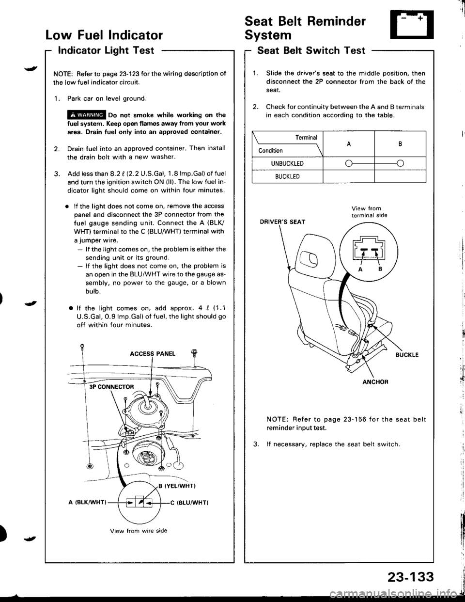
NOTE: Refer to page 23-123 for the wiring description of
the low fuel indicator circuit.
1. Park car on level ground.
@ oo not smoke whilc wolking on the
fuel system. Keep open tlames away from your work
area. Drain fuel only into an approved container.
2. Drain fuel into an approved container. Then install
the drain bolt with a new washer.
3. Add lessthan 8.2 t l2.2U.S.Gal, 1.8 lmp.Gal)of fuel
and turn the ignition switch ON {ll). The low fuel in-
dicator light should come on within lour minutes.
. lf the light does not come on. remove the access
panel and disconnect the 3P connector from the
fuel gauge sending unit. Connect the A (BLV
WHT) terminal to the C (BLU,/WHT) terminal with
a jumper wire.
- lf the Iight comes on, the problem is either the
sending unit or its ground.- lf the light does not come on, the problem is
an open in the BLU/WHT wire to the gauge as-
sembly, no power to the gauge, or a blown
bulb.
a lf the light comes on, add approx.4 ! (1.1
U.S.Gal. O.9 lmp.Gal) of fuel, the light should go
off within four minutes.
I
i
)
SeatSwitchTestBelt
1.Slide the driver's seat to the middle position. then
disconnect the 2P connector from the back of the
seat.
Check tor continuity between the A and B terminals
in each condition according to the table.
NOTE: Refer to page 23-156 for the seat belt
reminder input test,
3. lf necessary, replace the seat belt switch.
Terminal
c""dil----lB
UNBUCKLEDoo
BUCKLED
ANCHOR3P CONNECTOR
23-133