1998 HONDA INTEGRA wheel
[x] Cancel search: wheelPage 636 of 1681

Disassembly
13. Pull the knuckle outward. then remove the drive-
shaft outboard joint from the front wheel hub using
a plastic hammer.
KNUCKLE
DRIVESHAFT
l.Careful clamp the driveshaft in a vise with soft jaws,
then remove the set ring from the inboard joint.
Remove the boot bands on the inboard ioint and
outboard joint.
CAUTION: Take care not to damags th€ boot.
- lf the boot band is a welded type or a low profile
type boot band, carefully cut it off with a pair of
diagonal cutters.
2.
- lf the boot band is a double loop band type, raise
the band bend as shown.
OOUBI-E LOOP BANDReplace.
(cont'd)
16-5
Page 646 of 1681

Intermediate Shaft
Removal
Drain the transmission oil or fluid {see section 13 or
14t.
Remove the left driveshaft (see page 16-3).
Bemove the three dowel bolts.
Remove the intermediate sh8ft from the differential.
CAUTION: Hold the intermediate shaft horizontal
until it is clear ot th6 difforantirl to prevont damage
to thc ditf€rential oil seal.
7. Install the knuckle on the lower arm.
NOTE: Wipe off the grease before tightening the
nut at the ball joint.
CAUTION:
. Be careful not to damago the ballioint boot.
. Torque the castle nut to tho low€r torque speci-
tication, then tighten it only lar onough to align
th6 slot whh tho pin hols. Do not align the nut
by loosening.
,.<__coTTEF PtNCASTLE NUT12 x 1.25 mm49 - 59 N.m {5.0 - 5.0 kgf.m, 36 - t3 lbl.ft)
Beplace.On reassembly,bend the cotter pin
8. Install a new spindle nut, then tighten the nut.
9. Installthe front wheel with the wheel nuts.
NOTE: Before installing the wheel, clean the mating
surfaces of the brake disc and the wheel.
FRONT WHEELWH€EL NUT 12 x 1.5 mm108 N.m (11.0 kgt m,80lbf ft)
10.
NUT 22 x '1.5 mm181 N m 118.5 kgl.m, 134lbtftlNOTE: After tightening, use a drift tostake the spindle nut shoulderagainst the driveshatt.
Tighten the flange bolts and the new self-locking
nut with the vehicle's weight on the damper.
Refill the transmission with recommended oil or
fluid (see section 13 or 14).
11.
12. Check the front wheel alignment and adjust if nec-
essary (see page 18-4).
INTERMCOIATE SHAFT
16-15
Page 650 of 1681

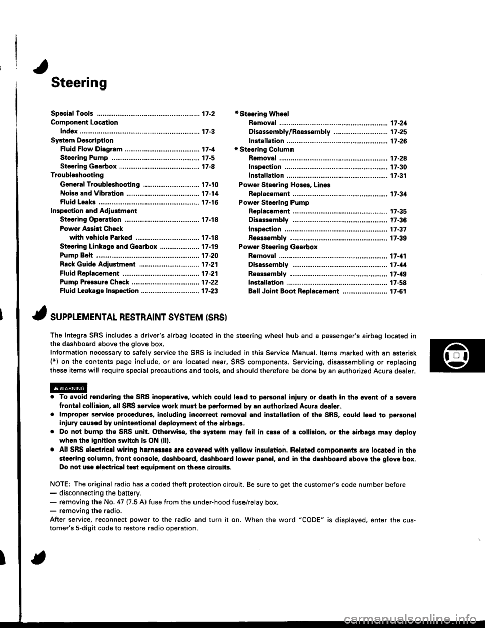
Steering
Componsnt Location
lndox
*Stooring Wheel
Removal ....
Disassombly/Ro8$.mbly
Disassombly ......
F08$€mbly
Powcr Stosring Gosrbox
R6moval
............................ 17-3
............. 17 -1
................ 17-16
............................. 17_25
17-30
17.31
.......17-21
Sy3tom DGcription
Fluid Flow Disgram
Steering Pump .............. 17-5
Stocring Goarbox ...17.8
Troublorhooting
Gonoral Troubleshooting .............................. 17.10
Noiso lnd Vibration ...... 17-1i[
Fluid Losk3
lnspoction
Installation
Powor Steering Hos6, Lino3
Roplacom€nt .................. 17.34
Powor Steoring Pump
RGplac6montlolpeqtion lnd Adiu3tm6nl
Stoo.ing Operation
Powor A$bi Chock
with v.hiclo Parked
Stcering Linkage 6nd Goarbox
Pump Bolt
17.18
17.18
17.19
17-20
17.35
t7-36
17 -37
r7-39
Inspoction
................... 17.41
Rack Guide Adiustmont ..........................-.-.-. 17 -21
Ffuid Rcplacemont ........17-21
Pump Prc&suro Chock ...,........................,..,..., 17 -22
Fluid Leakage Inrpection ............................... 17-23
Dissssembly
R€aEs€mbly
In3tallation........... 17_58
Ball Joint Boot Replacem.ni ........................ 17-61
17-U
17.49
J ,urrar*TNTAL REsrRArNr sysrEM (sRsr
The Integra SRS includes a driver's airbag located in the steering wheel hub and a passenger's airbag located inthe dashboard above the glove box,
Information necessary to safely service the SRS is included in this Service Manual. ltems marked with an asterisk(*) on the contents page include, or are located near, SRS components. Servicing, dissssembling or replacing
these items will require special pr6cautions and tools, and should therefore be done by an authorized Acura dealer.
. To avoid rondoring ths SRS inoparstivo. which could |rad to parsonal iniury or doath in the ov€nt of ! sev6.o
trontal collision, all SRS sarvice work must be perto.med by an authorizod Acura dsalor.. lmpropor 3orvic€ procadures, including inco[6ql rgmoval and inrtallation of the SRS, could l6ad to pgrsonal
iniury clus€d by unintentional doployment of the airbags,. Do nol bump tho SRS unh, (Xherwise, th6 3ystom may fail in cas€ ol a collision, or the airbags may d€ploy
when ths ignition switch is ON {ll).. All SRS electrical wiring harness€s aro covered with yallow insulation. Related component3 are located in ths
stcaring column. tront con3ol6, dashboard, d.shbolrd lower panel, and in the dashboard above ths glove box.
Do not u3o electrical test oquipm€nt on the3e circuii3.
NOTE: The original radio has a coded theft protection circuit. Be sure to get the customer's code number before- disconn€cting the battery.- removing the No. 47 (7.5 A) fuse from the under-hood fuse/relay box,- removing the radio.
After service, reconnect power to the radio and turn it on. When the word "CODE" is displayed. enter the cus-
tomer's 5-digit code to restore radio operation.
Page 652 of 1681

I
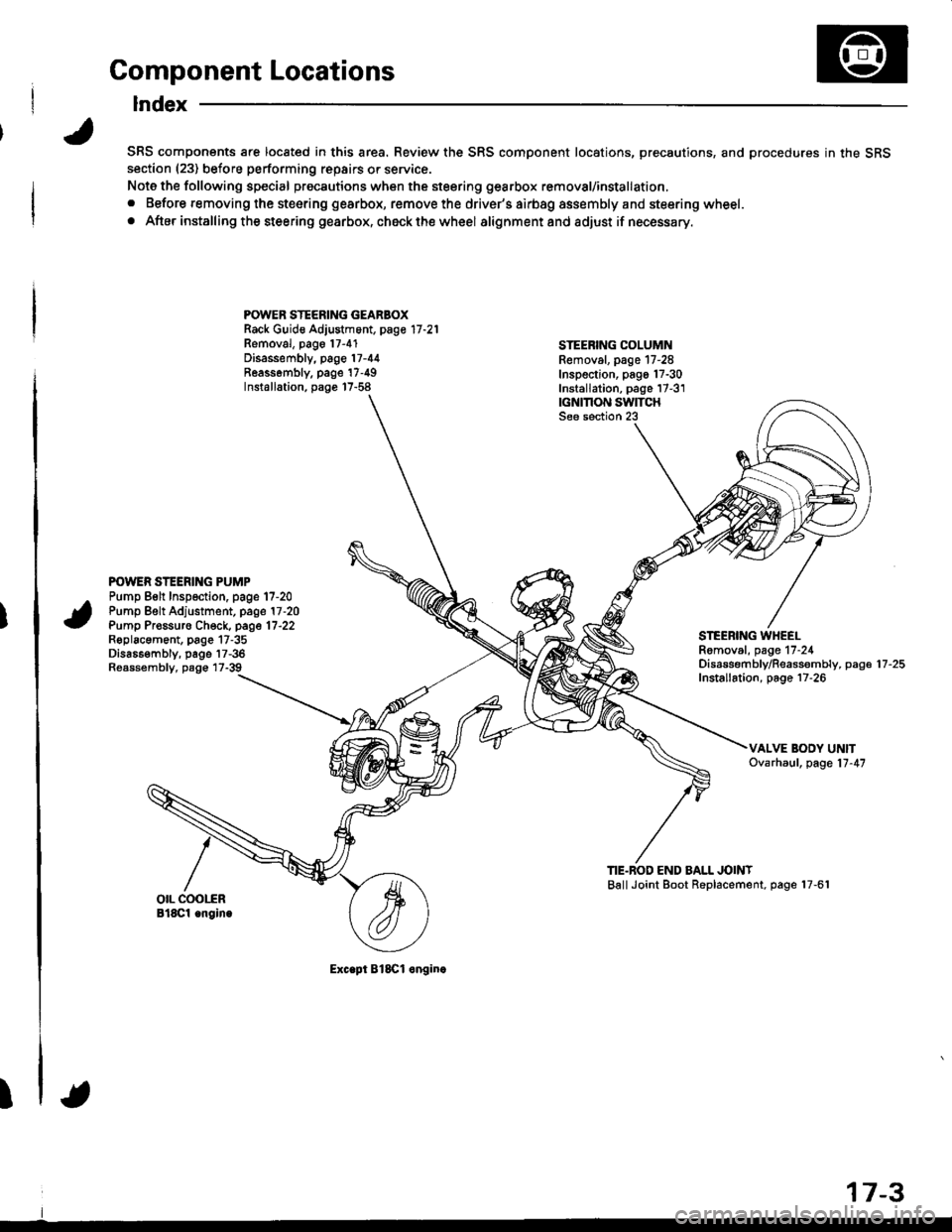
Component Locations
Index
SRS components are located in this area. Review the SRS component locations, precautions, and procedures in the SRSsection (23) before performing repairs or service.
Note the following special precautions when the steering gearbox removal/installation,
. Before removing the steering gearbox, remove the driver's airbag assembly and steering wheel.
. After installing the steering gearbox, ch6ck the wheel alignmentand adjust if necessary.
POWER STEERING GEARBOXRack Guid€ Adjustment, page 17 -21
Removal, pago 17-4'1Disassembly, page 17-44Reassombly. page'17-49Installation, page 17-58
STEEBING COLUMNRemoval. page 17-28Inspection, pago 17-30Installation, page 17-3'1|GNMON SWITCHSee section 23
POWER STEERING PUMPPump Belt Inspection. page 17-20Pump Belt Adjustment, page 17 -20
Pump Pr€ssuro Check, page 17'22Roplacament, page 17-35Dis686embly, page 17-36Reassembly, page 17-39
STEEBING WHEELRomoval, page 17-24Disassembf y/Reassembly, paga 17 -25
Installation, page 17-26
TIE.BOD END BALL JOINTBallJoint Boot Replacement, page 17-61
Exc.pt BlSCl onginc
17-3
Page 658 of 1681

INPUT SHAFT
High assist at lower speedsl
When steering resistance is high, such as when driving at low speed, or when turning the wheel with the car stopped, the
diiference in angle created between the input shaft and the valve opens the tluid passage on one side, and closes the fluidpassage on the other side, at each pair of orifices. The fluid pressure lncreases in the side of the power cylinder fed by thelarger fluid passage. This increased pressure pushes on the rack piston, allowing the steering wheel to be turned with light
effon. On the other side of the power cylinder, the return passage opens allowing the steering fluid to return through theinput shaft to the reservoir. The fluid passages to the power cylinder automatically change in size, increasing as the steer-ing resistance increases. In other words, the passages become larger and power assist increases when the steering effort
would normally be high, (for example, when parking or making low speed turns), and the passages become smaller andpower assist decreases when the steering effort would normally be low, (for example, when driving at high speeds or
straight ahead).
FLUIO PASSAGE TOPOWER CYLINDER
Ce) r.r;
VK
Pressure Control
Low assist at higher speedsl
When steering resistance is low, such as when driving at high speeds, or when driving straight ahead. the lnput shaft is
near or in the neutral position, so there is liftle or no flow to any of the power cylinder orifices. Most of the feed pressure
from the pump is bypassed to the reservoir. Because of this, the pressure stays the same in both sides of the power cvlin-
der, resulting in low or no assist.
RETURN PASSAGE{To RESERVOIR)
POWER CYLINDERlHigh fluid pressurelI
ALVE FTom PUMP
RESERVOIR
SECTION A-A
17-9
Page 659 of 1681

Troubleshooting
General Troubleshooting
Check the following before you begin:
o Has the suspension been modified in a way that would affect steering?
. Are tire sizes and air pressure correct?
. lsthe steering wheel original equipment or equivalent?
. ls the power steering pump belt properly adiusted?
. ls steering fluid reservoirtilled to proper level?
. ls the engine idle speed correct and steadyT
Hard steering (check the power assist, see page 17-18. It the torce is over 34 N (3.5 kgf, 7 7 lbf), proceed with this troubl*hooting l
Abnormalfluidpressur€ (lluid
pressure rs roohish)
Too low reliefpress{ire
Normal line and hos6
I
II
iFaulty valve body unit
Normal Abnormal
rlrl
l{
Faulty pump assembly Faulty tlow control valv6
Ch€ck the tegd and return circuit lines and hoso
between the gearbox and pump for clogging and
detormation.
Check pump fluid Pressuro {sespage 17'221.Mgasure stoady-stat€ fluid Pres_sure while idling with the both
valv6Iully opon.It should be 1,500 kPa (15 kgf/
cm,,213 psi) or below.
Normal
Check the flow control valve (seo page 17-37).. Check the valvs Ior smooth movemont in the hous-
Ing.. Check tho reliel valvo for leaks.
Measure pump reliet prgssure
while idling with the both vslveIully closed.It should b€ 6,400 - 7,400 kPa {65- 75 kgt/cm'�, 924 - 1,067 psi)
Normal reliel pressure
I
I
+
Go to pags 17-11
17-10
Page 660 of 1681

From page 17-10
Normal
Check lorce required to turn thewhool (see page 17-'18).Start the engine and measu16the force required to turn thewheel to the right and left.Difference of the force requiredto twn the wheel to the right andto the left should be 5 N (0.5 kgf,1 lbl) or below.
Deformed
I
iFaulty cylinder lines
Not bent
Adjustment OK
Faulty valve body unit
Abnormal --> Faulty gearbox
Ch€ck th6 pans other than the gearbox-related parts lorDrooer rolaton.
. . lmproper rotation ofthe steering column-related pan{s}----------------- . tau[y $eenng lornt. Faulty rack endtio-rod ond balljoints. Intgrferonce in the steering system
Normal -----> lmproperly adjusted rack guide
Check lor bent rack shaft.
Check pump fluid pressure (seepage 17-22).Turn the steoring wheel fully tothe right and l€ft while idlingwilh the pressure control valveIully open, and measure the Iluidpressure. lt should be 6,400 -
7,400 kPa (65 - 75 kgflcmr, 924 -
1,067 psi).
Normal
Ch€ck the gearbox.Remove the gearbox and mea-sure the pinion torque.The lorque should be;. 0.7 - '1.2 N.m (7 - 12 kgf.cm, 6 -
10 lbf.in) wjth the steering rackin the straight driving position.
Abnormal
Adjust the rack guide {see page17-211, and recheck the pinion
torque.
17-11
Page 661 of 1681

Troubleshooting
General Troubleshooting (cont'dl
Assist (excessively light steering) athigh speod.
Shock or vibration when wheel isturned to full lock.
Steering wheel will not return
smoothly.
a-, aa GrI r- tz
ll the problom is not correcled byadiusting the rack guide, adjustthe front wh66l alignment (see
s6ction 18).
Ch6ck th6 rack guide propgr ad-justment (see pago 17-21).
Check the rack guido lor proper
adjustment (see page 17-21).
Rack guid€ is adjusted properly.
lf the problem is not corrected byadjusting the rack guide, replscothe gearbox.Check the belt for slippage andadjust as nec€ssary {s6e page 17-20).
A and B cylinder lines are nor-mal, chgck wheol alignment (se€
section 18).
Whe6l alignment is abnormal,adjust as needod.
It should be 0.7 - 1.2 N.m {7 - 12kgl.cm.6 - 10 lbf.in) or belowwith the steering rack in thestraight ahoad driving position.
wh€el alignment is normal.R€mov€ the gearbox from thofram6 snd measure the pinion
torque on the gearbox.
lf the measurements are out ofsp€cifications. adjust the rackgurd9.
It the problom is not corrected byadiusting the rack guido. r€placethe goarbox.
{
I