Page 745 of 1681

)Installation
Typ€ R Model:
NOTE;
. Any bolts or nuts connected to rubber mounts or bushings should be tightened with the vehicle on the ground.. "L" is stamped on the left lower arm and "R" is stamped on the right lower arm.. "l UP LS" is stamped on the left upper arm and "l UP RS" is stampedon the right upper arm.. The right and left compensator arms are symmetrical. Install then with the "1 Up" mark facesing forward. After installing the suspension arm, checkthe rearwheel alignmentand adjustitif necessary(see page 18-4).
8 mm BOLT22 N.m (2.2 kgl m, 16 lbt.ftl
STABILIZER BARAlign the stabilizer markwith end of stabilizer bushing.
-ArUPPEB ARM
rz tot+,t \
\.d'. Ja),n[
_oY
t\
a
stLtcoNEGREASEBUSHINGADJUSTING BOLTIFLANGE BOLT}l0 x 1.25 mm6,4 N.m {6.5 kgt m,
FLANGE BOLT'10 x 1.25 mm5,[ N.m 15.5 kg[.m. 40 lbt.ftl
STABILIZER BUSHING
FLANGE BOLT10 x 1.25 mm
FLANGE BOLT10 x 1.25 mrn39 N.m (,r.0 kgf.m.29 lbtftl5/a N.m 15.5 kgl.m, a0
COMPENSATOR AFM
UPPER ARM
TRAILING ARM
FLANGE BOLT10 x 1.25 mm54 N.m 15.5 kgf.m, .{) lbf.ftl..- SILICONE.4@i cREAsECOMPENSATORARM BUSHING
FLANGE BOLI10 r 1.25 mm6,4 N.m (6.5 kgl.m, 47 lbf.Itl
FLANGE BOLT12 x 1.25 mm6a N.m 16.5 kgl.m, a7 lbf.ftl
, ror"orr /
l0 x 1.25 mm39 N.m 14.0 kgf.m, 29 lbt.ftl
FLANGE BOLT8 x 1.25 mm30 N.m 13.1 kgt m, 22 lbf.ftl
..- SILICONE.@ll GREASE
FLANGE BOLT10 x 1.25 mm54 N.m {5.5 kgt m, 40 lbtftl
LOWER ARM
LOWER ARM EUSHING
a
--- SILICONE@l GREASE
-- slLlcoNE&l GREASE
18-35
Page 1340 of 1681

Precautions/Procedures
Steering-related Precautions
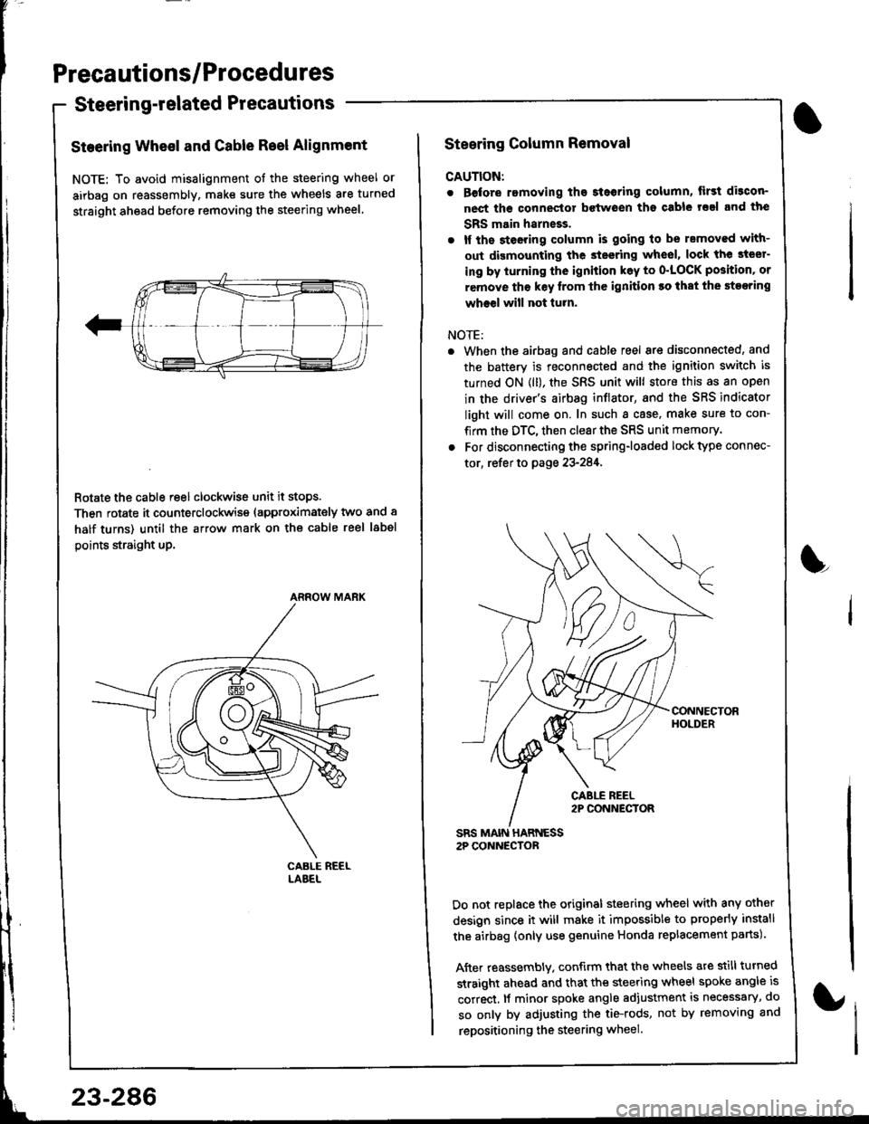
Steering Wheel and Gable Reel Alignment
NOTE: To avoid misalignment of the steering wheel or
airbag on reassembly. make sure the wheels are turned
straight ahead before removing the steering wheel.
Rotate the cable reel clockwise unit it stops.
Then rotate it counterclockwise (approximately two and a
half turns) until the arrow mark on the cable reel label
points straight up.
ARROW MARK
23-286
Steering Column Removal
CAUTION:
. Before romoving the steoring column, lirst di3con-
nect ths connector bctwoen tho csble rsal and the
SBS main harneEs.
. lf the steeting column is going to be rsmoved with-
out dismounting the steering wheel, lock the steer-
ing by iurning the ignition k6y to o'LOCK position' or
remove tho key lrom thc ignition ro that the steering
wheel will not turn.
NOTE:
When the airbag and cable reel are disconnected, and
the battery is reconnected and the ignition switch is
turned ON (ll), the SRS unit will store this as an open
in the driver's airbag inflator, and the SRS indicator
light will come on. In such a case, make sure to con-
firm the DTC, then clear the SRS unit memory.
For disconnecting the spring-loaded lock type connec-
tor, refer to page 23-284,
SRS MAIN HARNESS2P CONNECTOR
Do not replace the original steering wheel with any other
design since it will make it impossible to properly install
the airbag {only use genuine Honda replacement parts).
After reassembly. confirm that the wheels are still turned
straight ahead and that the steering wheel spoke angle is
correct, lf minor spoke angle adjustment is necessary, do
so only by adjusting the tie-rods, not by removing and
repositioning the steering wheel.
L
Page 1655 of 1681

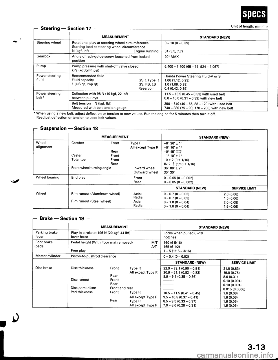
MEASUREMENTSTANDARD (NEWI
Steering wheelRotational play at steering wheel circumferenceStarting load at steering wheel circumferenceN (kgf, lbf) Engine running
0 - 10 (0 - 0.39)
34 (3.5,7 .71
GearboxAngle of rack-guide-screw loosened from lockedoosition20'MAX
PumpPump pressure with shut-off valve closedkPa (kgf/cm,, psi)6,400 - 7,400 (65 - 75, 924 - 1,067],
Power steeringfluidRecommended fluidFluid capacity GSR, Type Rf (US qt, lmp qtl cS, RS, LSReservoir
Honda Power Steering Fluid-V or S1.06 (1.12,0.93)
1.0 (1.06,0.88)
0.4 (0.42, 0.35)
Power steeringbelt*Deflection with 98 N (10 kgf,22 lbflbetween pulleys1 1.5 - 13.5 (0.45 - 0.531 with used belt8.0 - 10.0 (0.31 - 0.39) with new belt
Belt tension N (kgf, lbf)Measured with belt tension gauge390 - 540 (40 - 55, 88 - 120) with used belt740 - 880 (75 - 90, 170 - 2001with new belt
SteeringSection 17
* When using a new belt, adjust deflection or tension to new values. Run the engine for 5 minutes then turn it off.Readiust deflection or tension to used belt values.
Suspension - Section 18
BrakeSection 19
Unit of length: mm (in)
$t
MEASUREMENTSTANDARD (NEWI
WheelalignmentCamber Front Type RAll except Type RRearCaster FrontTotal toe FrontRearFront wheel turning angle Inward wheelOutward wheel
-0'30'r 1"-0' 10'r 1.-0" 45'�1?:i3i1. 10'�1 1.0!210!1116!,lN 2 lf (t7t6 1 1716136. 00'1 2"30'30'
Wheel bearingEnd play FrontRear0 - 0.05 (0 - 0.002)0 - 0.05 (0 - 0.002)
WheelRim runout (Aluminum wheel) AxialRadialRim runout (Steel wheel) AxialRadial
STANDARD (NEW}SERVICE LIMIT
0 - 0.7 (0 - 0.03)0 - 0.7 (0 - 0.03)0 - 1.0 (0 - 0.04)0 - 1.0 (0 - 0.04)
2.0 (0.08)
1.5 (0.06)2.0 (0.08)1.5 (0.06)
MEASUREMENTSTANDARD (NEW}
Parking brakeleverPlay in stroke at 196 N (20 kgf,44 lbf)lever forceLocks when oulled 6 -10
notches
Foot brakepedalPedal height (With floor mat removed)
Free play
M/TAtT160 (6 5/161165 rc 1nl1-5(1/16-3/16)
Master cylinderPiston-to-oushrod clearance0 - 0.4 (0 - 0.021
Disc brakeDisc thickness Front Type RAll except Type RRearDisc runout FrontRearDisc parallelism Front and rearPad thickness Front Type R
All except Type RRear Type RAll except Type R
STANDARD (NEWISERV]CE LIMIT
22.9 - 23.1 (0.90 - 0.91120.9 - 21.1 (0.82 - 0.83)
1= t (0.35-0.361
10.5 - 11.5 (0.41 - 0.45)9.5 - 10.5 (0.37 * 0.41)8.5 - 9.5 (0.33 - 0.37)7.0 - 8.0 (0.28 - 0.31)
21.0 (0.83)19.0 (0.75)
8.0 (0.31)
0.10 (0.004)
0.10 (0.004)
0.015 (0.0006)1.6 (0.06)
1.6 (0.06)1.6 (0.06)
1.6 (0.06)
Page 1659 of 1681

:/
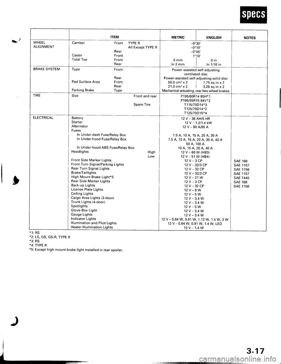
*1: RS*2: LS, GS, GS.R, TYPE R*3: RS+4: TYPE R*5: Except high mount brake light installed in rear spoirer.
ITEMMETRICENGLISHNOTES
WHEELALIGNMENTCamber Front TYPE RAll Except ryPE RRearCaster FrontTotal Toe FrontRear
-0"30'_0"10,_0"45'
1"10'omm I oinIn 2 mm I In 1/16 inBRAKE SYSTEMType Front
RearPad Surface Area FrontRearParking Brake Type
Power-assisted self-adjustingventilated discPower-assisted self-adlusting sol id disc50.0 cm2 x 2 | 7.75 sq in x 221.0 cm, x 2 | a.ZO sq in x 2Mechanical actuating, rear two wheel brakesTIRESize Front and rear
Spare Tire
P195/60R14 85H*1P195/55R15 84V*2T115t0D14*3T125/70D14*2T125n0D15*4
ELECTRICALBatteryStarterAlternatorFusesIn Under-dash Fuse/Relay BoxIn Under-hood Fuse/Relay Box
In Under-hood ABS Fuse/Relay BoxHeadlights
Front Side Marker LightsFront Turn Signal/Parking LightsRear Turn Signal LightsBrake/TaillightsHigh Mount Brake Light*5Rear Side Marker LightsBack-up LightsLicense Plate LightsCeiling LightsCargo Area Lights (3-door)Trunk Lights (4-door)SpotlightsGlove Box LightGauge LightsIndicator Lightslllumination and Pilot LightsHeater lllumination Lights
HighLow
12 V _ 36 AH/5 HR12V -1.2/'t.4kW
12V-90A/85A
7.5 A, 10 A, 15 A, 20 A, 30 A7.5 A. 10 A, 15 A, 20 A, 30 A, 40 A50A,100A10A,15A,20A,40A12V-60W(H83)12V -51 W (HB4)12V-3CP12V _3213 CP12V _32 CP12V-3213CP't2v -21 W12 V - 3 CP12V -32CP
12V_8W12V-5W12V-3.4W12V-3.4W12V_5W12V-3.4W12V-3.4W12 V - 0.84 W, 0.91 W, 1.12W, 1.4W, 3 W12 V - 0.84 W, 0.91 W, 1.4 W, LED12V-1.4W
SAE 168SAE 1157SAE 1156SAE 1157SAE 7440SAE 168SAE 1156
3-17
Page:
< prev 1-8 9-16 17-24