Page 790 of 1681

Diagnostic Trouble Code (DTC)
DTG Erasure (MES Mode)
NOTE: This operation can also be done with the Honda PGM Tester.
1. Connect the SCS short connector to the service check connector (2P) underthe glove box.
2, Deoress the brake pedal.
3. Turn the ignition switch ON (ll) while keeping the brake pedal depressed.
4. Afterthe ABS indicator goes off, release the brake pedal.
5. After the indicator comes on, depress the brake pedal again
6. After the indicator goes off, release the brake pedal again.
7. After a few seconds, the ABS indicator blinks twice and the DTC is erased. lf the indicator does not blink twice, repeat
steps 1 through 6. lf the indicator stays ON after the indicator blinks twice. check the DTC because a problem was
detected during initial diagnosis before shifting to DTC Erasure mode.
8. Turn the ignition switch OFF, and remove the SCS short connector.
Conditions lor DTC erasure
. Vehicle speed is 6 mph (10 km/h) or less.
. The SCS short connector is connected before the ignition switch is turned ON (ll).
. The brake pedal is depressed before the ignition switch isturned ON (ll)
ON
ABS INDICATOF
OFF
DEPRESSED
BRAKE PEDAL
RELEASED
Snilion switch
illr'I'
0.3soc.
'-------t
II2 sec,4 sgc.4 sec.5 aac.
0.3s6c.with in 3 s6c.with in 3 ssc.with in 3 s€c.
T
19-38
Page 797 of 1681

l
DTC121416, 18: Wheel Sensor {Electrical Noise/lntermittent lnterruptionl
- Wilh the ignition switch ONlll), the ABS indicator doesnot go off.- With the SCS service connec-tor connectcd (3e6 page 19-37), DTCa 12, 14, 16, or 18.reindicated.
Visually check for appropriatewheel sensor and pulser installation (see table).
Reinstall or replace th6 eppropri-ats wh6el sensor or puber.
Ch€ck lor a short to wire in thoone wheel s6nsor circuit:1. Disconnect the ABS controlunit 22P connector.2. Measu re the resistancebetween the appropriatewheel sensor (+) and (-) circuit terminals (see table).
Repair short to wire between theappropriate wheel sensor {+) and{-l circuits.ls there less than 450 0?
Check lor a short to .nother wirein lhe wheel sensor circuits:Check for continuity between theappropriate wheel sensor (+) circuit terminal and other wheelsensor (+i circuit terminals (see
table)-
R€psir short to wire between theappropriale wheol sensor andthe other wheel sensor.ls there continuity?
Eraso the DTC and test-drive thevehicle. lf ABS indicator comeson and same OTC is indiceted,reDlace the ABS control unil.
NOTE: ll the ABS indicator comes on for the reasons described below, the indicator should go
off when you test'drive the vehicle at speeds above 19 mph 130 km/h).. Only the drive wheels rotated. The vehicle spun. Electrical noise
DTCAppropriate Wheel Sensor
12Right - front
14Left front
Right - rear
18Left rear
DTCAppropriate Terminal
{+}Side(-)Side
12 (Right-front)No. 9: FRW (+)No.8: FRW (-)
'14 {Left-front)No. 7: FLW {+)No.6: FLW (-)'16 {Right-rear)No. 19: RRW 1+)No.20: RRW ( )
18 (Left-rear)No. 17: RLW (+)No. 18: RLW ( )
DTCAppropriateTerminalOther Terminal
12 (Right-tront)No.9: FBW (+)No. 7: FLW 1+)No. 19: RRW (+)No. 17: RLW (+)
14 (Left-front)No.7: FLW (+)No.9i FRW (+)No. 19: RRW (+)No. 17: RLW (+)
16 (Right-rear)No. 19r RRW {+)No.9: FRW (+)No. 7: FLW 1+)No.17: RLW (+)'18 (Left-rear)No. 17: RLW (+)No.9: FRW (+)No.7; FLW (+iNo. 19: RRW (+i
'
L
19-45
Page 804 of 1681

Troubleshooting
- When the v€hicl€ starts, theABS indicator comes on.- With the SCS service connec-tor connected lsee page 19-371. DTC 52 is indicated.
DTC 52: Motor Stuck OFF
l
l
NOTE: Connect the pump motor relayconnector terminal No.3 to No. 4 for amoment, and rechock the fuse. It the fuseis blown, check lor a short to bodyground in the motor power source circuit.
NOTE: Connect the pump motor relayconnector terminal No. 3 to No. 4 for amoment, and recheck the fuse. lf thetuse is blown, check for a short to bodyground in the MCK circuit.
PUTIIP MOTOR RELAY CONNECTOB
+B
Check the PMR circuit.lTo page 19-54)
JUMPER WIRE
Terminal side of temale terminals
Check fo. an open in the MOTORcircuit:1. Disconnect the pump motor
2. Connect the pump motorrelay connector terminal No.3 to No. 4 with a jumper wire.3. Measure the voltage betweenthe pum p motor connectorterminal No. l and bodyground,
PUMP MOTOR CONNECTON
u_l_lj
I MOTOR tWHTt
n)Y-L
Terminal side of temale terrninals
YES
Check the ABS MOTOR (40 A)fuse in the under hood ABSfuse/relay box, and reinstall thetuse if it is OK.
Feplace the fus6 and recheck.
check the ABS uNlT (10 A) fusein the under-hood ABS fuse/relaybox, and reinstall the fuse if it isoK.
Reolace the tuse and r.check.
Roplece tha pump motor .el.y.
Check the motor circuit:Connect the pump motor relayconnector terminal No. 3 to No, 4with a jumper wire for a moment.
Does the pump motor operate?
Rop.i. opan in the wir. betwconthc underhood ABS fuso/r6ltybox and the pump motor,
{To page 19-53}
Page 812 of 1681
DTC 71: Different Diameter tire
- While driving the vehicl€. theABS indicator comes on.- With the SCS sorvico connec-tor connocted (see page 19-371. DTC 71 is indicated.
Troubleshooting
Central Processing Unit (CPU)
- With the ignition switch ON(lll, tho ABS indicator does
not go off.- With the SCS service connec-lor connectgd (sss page 19-
3?), DTC 81 is indic€ted.
Problem ve.ification:1. Erase the DTC.2. Test-drive the vehicle.
Does the ABS indicatorcome on and is DTC 81 indicated?
R€place th6 ABS control unit.
lntermittent failure; the vehicle is
OK rt this time.
19-60
Page 1124 of 1681

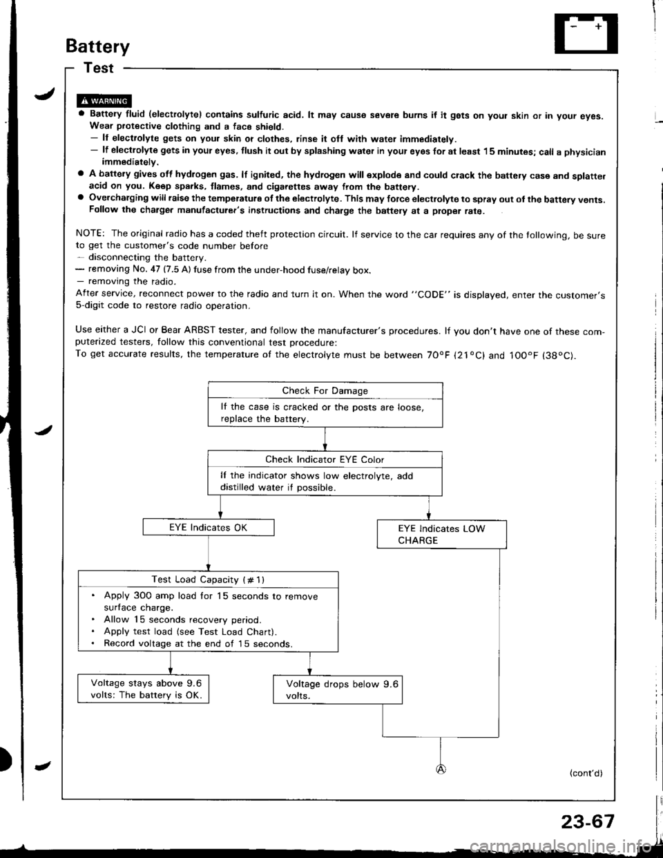
Battery
a Battery fluid (electrolytel contains sulfuric acid. lt may causo severe burns if it gsts on yout skin or in your eyes.Wear piotective clothing and a face shield.- ll electrolyte gets on your skin or clothes, rinse it ofl with water immediately.- lf electlolyte gets in your eyes, tlush it out by splashing water in your eyes for at least 15 minutes; call a physicianimmediately.
a A battery gives off hydlogen gas. lf ignited, the hydrogen will explode and could crack the battery case and splatte.acid on you. K6ep sparks, flames, and cigarettes away from the battery.a Overchalging will raisc the temperatulg of the electrolyte. This may force electrolyte to spray out ol the battery vents.Follow the chatge. manutacturer's instructions and charge the baftely at a ptope. rate.
NOTE: The original radio has a coded theft protection circuit. lf service to the car requires any of the tollowing, be sureto get the customer's code number before- disconnecting the battery.- removing No. 47 (7.5 A) fuse from the under-hood fuse/relay box.- removing the radio.
After service, reconnect power to the radio and turn it on. When the word "CODE" is displayed, enter tne customer's5-digit code to restore radio operation,
Use either a JCI or Bear ARBST tester, and follow the manufacturer's procedures. lf you don't have one of these com-puterazed testers, follow this conventional test Drocedure:To get accurate results, the temperature of the electrolyte must be between 70'F {21oC} and IOOoF (38oC).
lf the case is cracked or the posts are loose,
reDlace the batterv.
lf the indicator shows low electrolyte, add
distilled water if possible.
Test Load Capacity (# 1l
. Apply 3O0 amp load for 15 seconds to remove
surface charge.. Allow 15 seconds recovery period.. Apply test load {see Test Load Chart).. Record voltage at the end of l5 seconds.
Voltage stays above 9.6
volts: The battery is OK.
(cont'd)
Page 1332 of 1681
!
Gomponent/Wiring Locations Index
SRS INDICATOR LIGHT(ln the gauge assembly)Troubleshooting, page 23-287Gauge assembly, page 23-126
To HORN SWITCH
CABLE REELReplacement,page 23-322
DRIVER'S AIRBAGReplacement. page 23-317Disposal, page 23-320To DRIVER'S AIRBAG
DASHBOARD WIRE HARNESSFRONT PASSENGER'SAIRBAGBeplacement, page 23-317Disposal, page 23-320
to SRS INDICATOR LIGHT in GAUGE ASSEMBLY5P CONNECTOR
SRS MAIN HARNESSTo MAINWIRE HARNESS3P CONNECTOR
SRS MAINHARNESSto UNDER-DASHFUSE/RELAYBOX2P CONNECTOR
HARNESSto FRONT PASSENGERS AIRBAG2P CONNECTOR
SRS MAIN
SERVICE CHECXCONNECTOR {2PIIBRNAAIHT, BLK]to CABLE REEL2P CONNECTOR
MAIN WIRE HARNESSto DASHBOARD WIREHARNESS16P CONNECTOR
ERASE SIGNAL (MES}SRS UNITGBOUNOSRS MAIN HARNESSSRS UNIT(lncluding safing sensorano rmpact sensor)R6placement, page 23-326
2P CONNECTORSRS MAIN HARNESSto SRS UNIT18P CONNECTOR
S\--0
[GRN, GRNI or IWHT, BLKI
23-27A
Page 1333 of 1681

Description
I
J)
)
'\' '\, ili \.-.-1 i^\\,,; i \
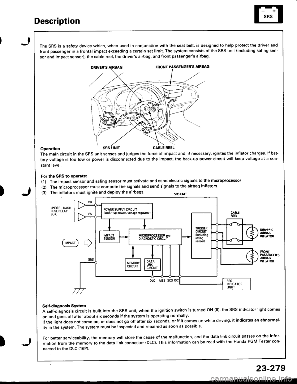
The SRS is a safetv device which, when used in coniunction with the seat belt, is designed to help protect the driver and
front passenger in a frontal impact exceeding a cenain set limit. The system consists ot the SRS unit (including safing sen-
sor and imDact sensor), the cable reel, the driver's airbag, and front passenger's airbag
Operation t'Its
The main circuit in the SRS unit senses and judges the force ot impact and, il necessary, ignites the inflator charges. If bat-
tery voltage is too low or power is disconnected due to the impact, the back-up power circuii will keep voltage at a con-
stant level.
For the SRS to operate:
(1) The impact sensor and safing sensor must activate and send electric signals to lhe mictop.Goi
{2) The microprocessor must compute the signals and send signals to the airbag inflators'
(3) The inflators must ignite and deploy the airbags sE Lr.r
UNDER DASHFUSE/RELAYBOX
Dnftr sAtacranroq
IIMPACT I ] )
F80t{TPASSEI{GEffSAIRSAGINFLAIOR
Drc MES SCS rDC
Self-diagnosis System
A self-diagnosis circuit is built into the sRs unit; when the ignition switch is turned oN (ll), the sRS indicator light comes
on and goes off after about six seconds if the system is operating normally'
lf the light does not come on, or does not go off after six seconds, or if it comes on while driving. it indicates an abnormal-
ity in the system. The system must be inspected and repaired as soon as possible'
For better servicesbility. the memory will store the cause of the malfunction, and the data link circuit passes on the infor-
mation from the memory to the data link connector (DLC). This information can be read with the Honda PGM Tester con-
nected to the DLc (16P).
23-279
J
Page 1334 of 1681
Circuit Diagram
FRONTPASSENGEF'SAJRBAGINFLATOR
f\4r
tlGRN GRN(YEL) (BLi.,'YEL)
I
G701
IGNITIONswtTcH
SRS INOICATOF CIBCUIT(ln the gauge assembly)
8LU
I
I
siEi'
IGRN
GRN(8RN)
I?
RNAVHT BRII/WHTlltl\---7 \*7
ECM SERVICECHECKcoirNEcTon
WHT/BLK +WHT
t"'
DATA LINKCONNECTOF(DLC)(r6P)
UNDEF-DASHFUSURELAY80x
ELKRED
J
PGM-FImain r€lay
MEIiIORY ERASEr2pt SIGNAL (MESIcoNNECToR (2P)
SRS UNIT TERMJNALS
BLX
G201G401
-NOER.NOOD FUSE/RELAY BOX
SRS INDICATORLIGHT 0.4W)
10 14 1 13 6 7(VA) 3(VB)SRS UNIT16 17 15 9188
DRIVER'SAJFBAGINFLATOR
1367I
10,/1,/1314151718
lerminal sde o{ male tefinnals
23-280
\'