1998 HONDA INTEGRA open hood
[x] Cancel search: open hoodPage 1028 of 1681
Troubleshooting
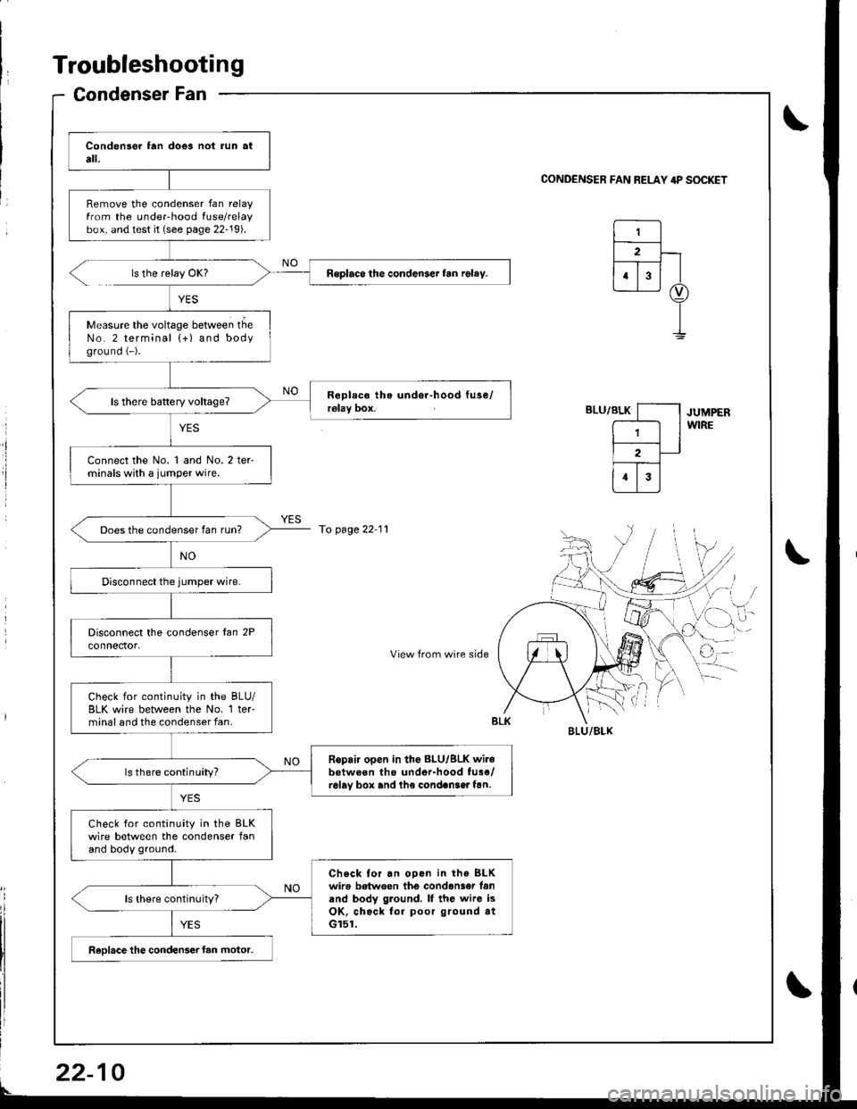
Condenser Fan
0
Remove the condenser fan relayfrom the underhood fuse/relaybox, and test it (see page 22-19).
Roplaco the condenser fan rgley.
Measure the voltage between tlieNo. 2 terminal {+) and bodyground (-).
Connect the No. 1 and No. 2 ter-minals with a jumper wire.
Does the condenser fan run?
Check for continuity in the BLU/BLK wire between lhe No. 1 ter'minal and the condenser fan.
Ropair open in the BLU/BLK wir.between tho undor-hood fu3e/relay box and lh€ condan3er fan.ls there continuity?
Check for continuity in the BLKwire between the condenser fanand body ground.
Check tor an ooen in the BLKwir6 betwoen the condan3er fanand body ground. lf the wire isOK, check for poor ground atGr51.
ReDlace the condenser fan motor,
CONDENSER FAN RELAY 4P S(rcKET
ls the relay OK?
YES
RoDlace the undor-hood tuse/r€lay box.JUMPERWIRE
To page 22 11
',,/-i, /
cr-i,
View from wire sideq
BI-U/BLX
22-
Page 1030 of 1681
Troubleshooting
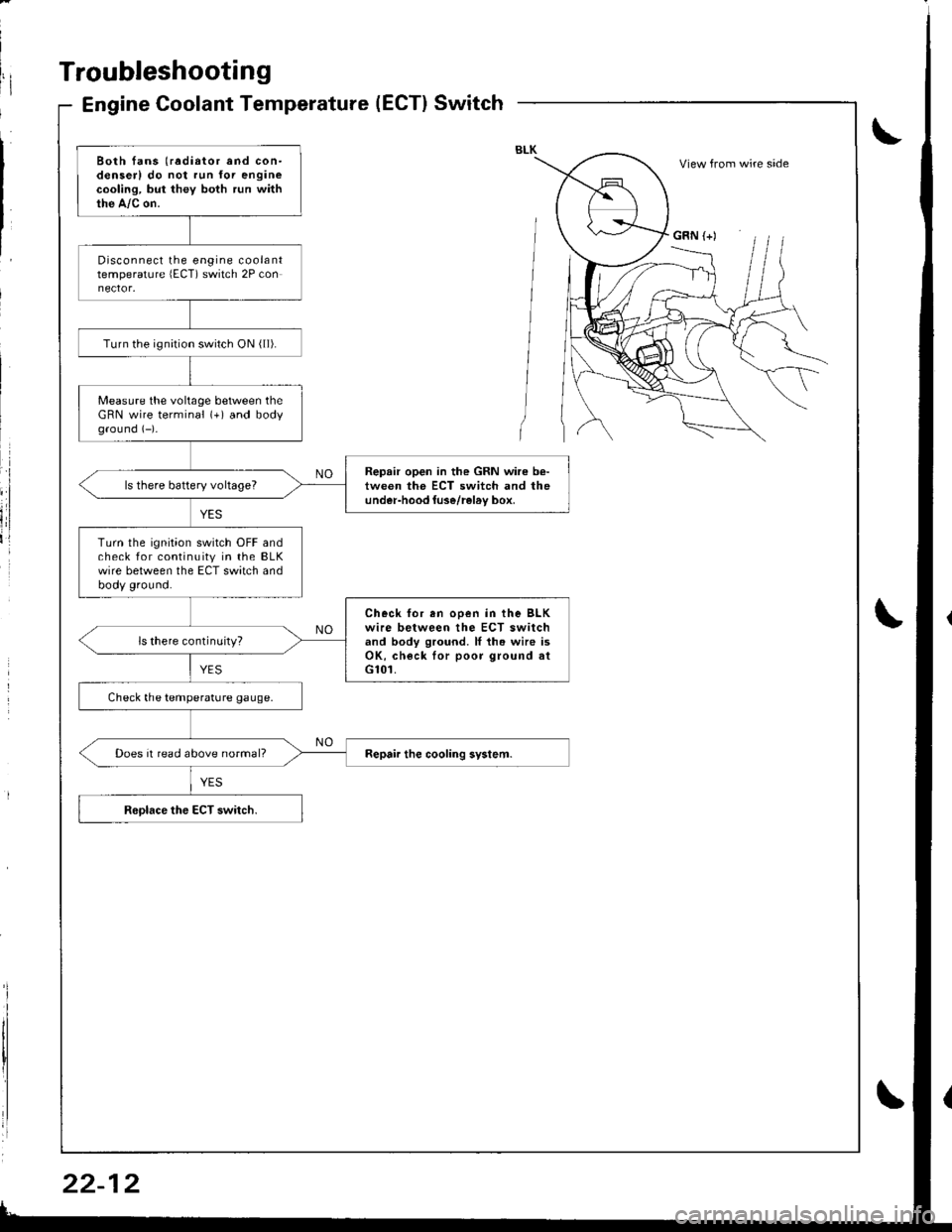
Engine Coolant Temperature(ECT}Switch
Both fans (radiator and con-denserl do not run for enginecooling, but they both run withthe A,/c on.
Disconnect the engine coolanttemperature lECT) switch 2P con
Turn the ignirion switch ON ( ll).
Measure the voltage between theGRN wire terminal (+) and bodyground (-)-
Repair open in the GRN wire b€-tween the ECT switch and theunder-hood luse/rel6v box,ls there battery voltageT
Turn the ignition switch OFF andcheck for continuity in the BLKwire between the ECT switch andbody ground.
Check for en ooen in the BLKwire between the ECT switchand body ground. ll th. wire isOK, check lor poor ground atG101.
ls there continuity?
Check the temperature gauge.
Does it read above normal?
View from wire side
GRN (+)
Page 1031 of 1681
BothFans
)
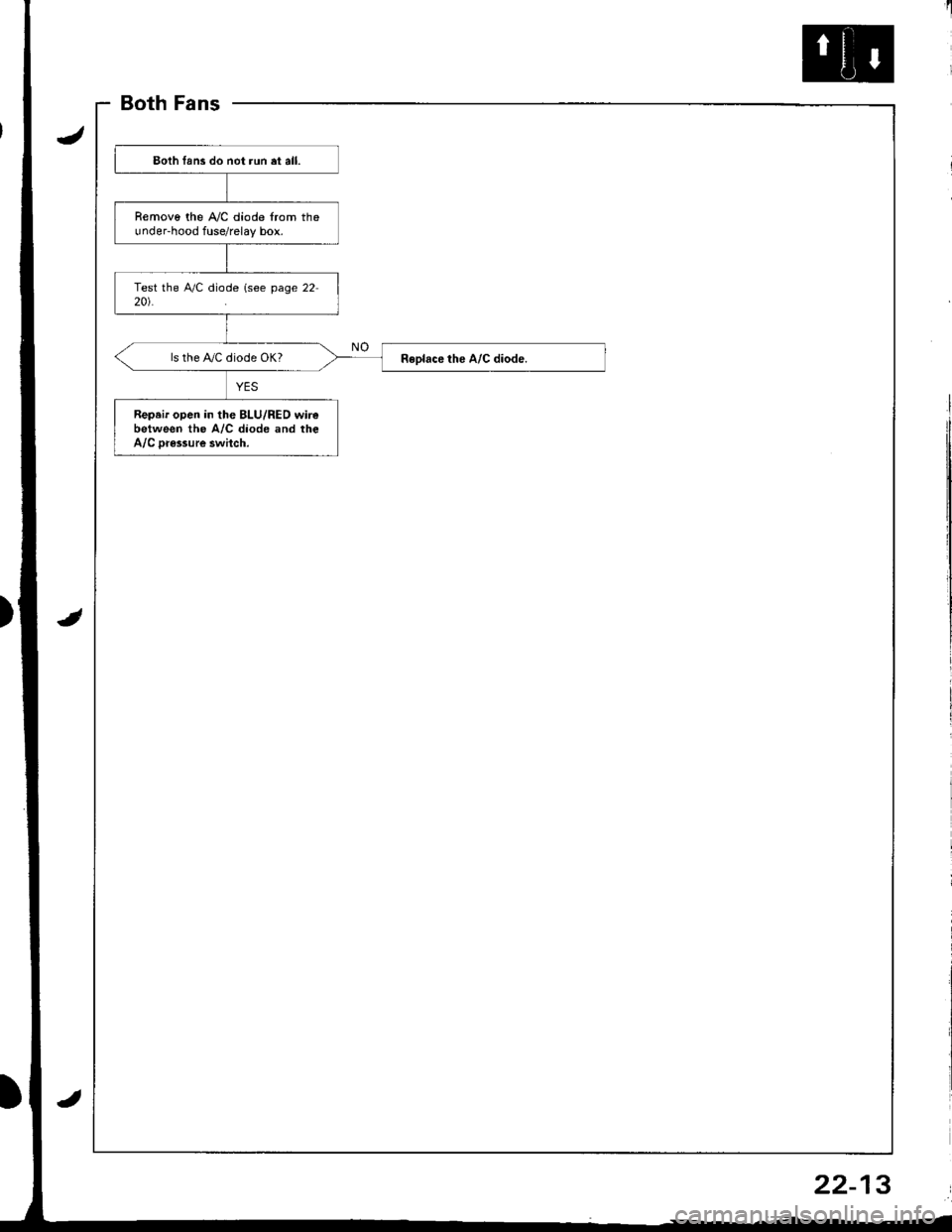
Eoth lans do not run et all.
Removo the A,/C diode from theunder-hood fuse/relay box.
ls the IVC diode OK?
Repeir open in the BLU/RED wirebetween the A/C diode and theA/C Dr€ssure swhch.
22-13
Page 1032 of 1681
Troubleshooting
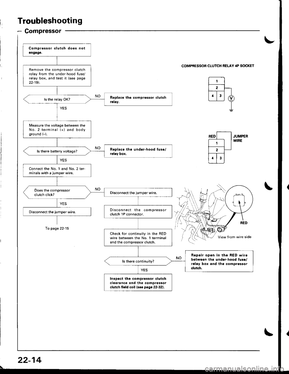
- Compressor
Remove the compressor clutchrelay trom the unde.hood tuse/relay box, and test it {see page
22-19t.
Measure the voltage beNveen theNo.2 terminal (+) and bodyground (-).
ls there battery voltage?
Connect the No. 1 and No. 2 terminals with a jumper wire.
Discon nect the compressorclutch 1P conoector.
Check lor continuity in the REDwire betlveen the No. 1 terminaland the compressor clutch.
Reprir open in tha BED wirabotwoon th6 undar-hood fusc/rolay box and lhs comp.osrorclutch.
In3p6ct th€ compre3sor clulchclear'nc€ and the comDressorcfutch ti€fd coil (se€ ptge22-321.
\-
COMPRESSOR CLUICH RELAY 'P SOCKET
JUMPERWIRE
\
To page 22-15
22-14
\
Page 1042 of 1681
A/C System Service
Performance Test
The performance test will help determine if the air con,
ditioner system is operating within specifications.
Use only service equipment that is U.L.-listed and is cer,
tified to meet the requirements of SAE J2210 to remove
HFC-134a (R-134a) from the air conditioner svstem.
CAUTION: Exposure to air conditioner retrigerant and
lubricant vapor or mist can irritate eyes, nose and
throat. Avoid breathing the air conditioner refrigerant
and lubricant vapor or mist.
lf accidental system discharge occurs, ventilate work
area before resuming service.
R-134a service equipment or vehicle air conditioner sys-
tems should not be pressure tested or leak tested with
compressed arr.
@ some mixtures of air and R-134a have
been shown to be combustible at elevated Dressures
and can result in fire or explosion causing iniury orproperty damage. Never use compressed air to pressure
test R-134a service equipment or vehicle air conditioner
systems.
Additional health and safety information may be
obtained from the refrigerant and lubricant manufactur-
ers.
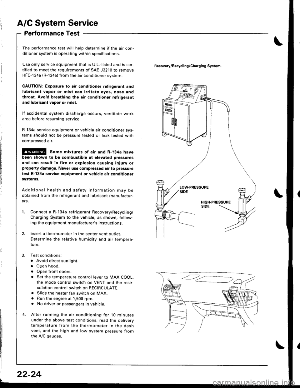
Connect a R-134a refrigerant Recovery/Recycling/
Charging System to the vehicle, as shown, follow-
ing the equipment manufacturer's instructions.
Insen a thermometer in the center vent outlet.
Determine the relative humidity and air tempera-
IUre.
Test conditions:
. Avoid direct sunlight.
. Open hood.
. Open lront doors.
. Set the temperature control lever to MAX COOL,
the mode control switch on VENT and the recir-
culation control switch on RECIRCULATE.. Slide the heater fan switch on MAX.. Run the engine at 1.500 rpm.. No driver or passengers in vehicle.
After running the air conditioning for'10 minutes
under the above test conditions, read the delivery
temperature from the thermometer in the dashvent, and the high and low system pressure from
the A,/C gauges.
Recovo.v/Recycling/Charging System.
LOW.PRESSURE
l
22-24
Page 1135 of 1681
Starting System
Starter Test (cont'dl
Check Cranking rpmr
Engine speed during cranking should be above 1OO rpm.
lJ speed is too low, check for:
a Loose batlery or starter terminals
a Excessively worn starter brushes
a Open circuit in commutator segments
a Dirty or damaged helical spline or drive gear
a Defective drive gear overrunning clutch
Check Starter Disengagement:
Press the clutch pedal all the way in (M/T), turn rhe igni
tion switch to "lll" and release to "11".
The starter drive gear should disengage from the flywheel
or torque converter ring gear when you release the key.
It the drive gear hangs up on the flywheel or torque con-
verter ring gear, check for:
a Solenoid plunger and switch mallunction
a Dirty drive gear assembly or damaged overrunning
clutch
5. Check for an open in the BLK/WHT wire circuit be
tween the starter and ignition switch, and con-
necrors,
6. Check the ignition switch (see page 23-71).
7. On cars with automatic transmission, check the A/Tgear position switch (neutral position switch) and
connector. On cars with manualtransmission, check
the starter cut relay, clutch interlock switch, and
connectors.
NOTE: Check the No. 42 (40 A) fuse in the under,hoodfuse/relay box for the starter cut relay.
Check Jor Wear and Damage:
The starter should crank the engine smoothly and stead,ily. lf the starter engages, but cranks the engine errati
cally, remove it. Inspect the starter, drive gear, andllywheel or torque converter ring gear lor damage.
a Check the drive gear overrunning clutch for binding
or slipping when the armature is rotated with the drivegear held. Replace the gears i{ damaged.
Check CJanking Voltage and Current Draw:
Cranking voltage should be no less than 8.O volts.
Current draw should be no more than * amperes.* 1.2 kW: 27O A
1 .4 kW: 360 A
It cranking voltage is too low, or current draw too high,check for:
a Dead or low charged batterya Open circuit in starter armature commutator segmentsa Starter armalure dragging
a Shorted armature windinga Excessive drag in engine
Page 1196 of 1681
Maintenance Reminder Unit Input Test
)
v
t
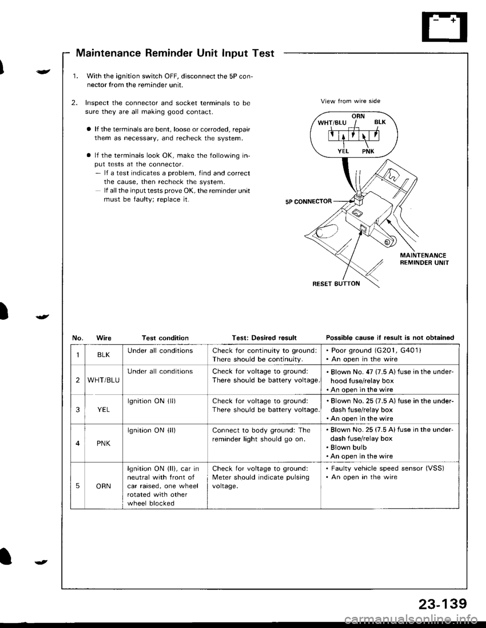
1.With the ignjtion switch OFF, disconnect the 5P con-
nector from the reminder unit.
Inspect the connector and socket terminals to be
sure they are all making good contact.
a lf the terminals are bent, loose or corroded, repair
them as necessary, and recheck the system.
a lf the terminals look OK, make the following in-
put tests at the connector.- lf a test indicates a problem, find and correct
the cause, then recheck the system.
lf all the input tests prove OK, the remind€r unit
must be faulty; replace it.
2.View from wire side
MAINTENANCEREMINDER UNIT
No.WileTest conditionTest: Dosired resultPossible cause it lesult is not obtained
ORN
IBLKUnder all conditionsCheck for continuity to ground:
There should be continuity.
. Poor ground (G201, G4011. An open in the wire
2WHT/BLU
Under all conditionsCheck for voltage to ground:
There should be battery voltage
. Blown No. 47 (7.5 A) fuse in the under-
hood fuse/relay box. An open in the wire
3YEL
lgnitionONflr)Check lor voltage to ground:
There should be battery voltage.
. Blown No.25 {7.5 A) fuse in the under-
dash fuse/relay box. An open in the wire
4PNK
lgnition ON {ll)Connect to body ground: The
reminder light should go on.
Blown No.25 (7.5 Alfuse in the under-
dash fuse/relay box
Blown bulb
An open in the wire
5ORN
lgnition ON (ll), car in
neutral with front of
car raised, one wheel
rotated with other
wheel blocked
Check for voltage to ground:
Meter should indicate pulsang
voltage.
. Faulty vehicle speed sensor (VSS)
. An open in the wire
t
23-139
Page 1206 of 1681
){r/
Control Unit Input Test
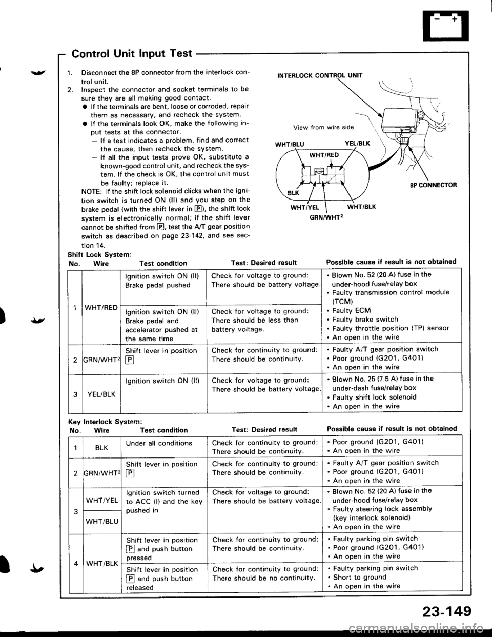
1. Disconnect the 8P connector from the interlock con-
trol unit.
2. lnspect the connector and socket terminals to be
sure they are all making good contact.
a It the terminals are bent, loose or corroded, repair
them as necessary, and recheck the system.
a lf the terminals look OK, make the following in-
put tests at the connector.- lf a test indicates a problem, tind and correct
the cause, then recheck the system.- lf all the input tests prove OK, substitute a
known-good control unit, and recheck the sys-
tem. lf the check is OK, the control unit must
be faulty; replace it.
NOTE: lf the shift lock solenoid clicks when the igni-
tion switch is turned ON (ll) and you step on the
brske Dedal (with the shift lever in E). the shift lock
system is electronically normal; if the shift lever
cannot be shifted from fl, test the 46 gear position
switch as described on page 23-142, and see sec-
tion 14.
Shift Lock System:
No. Wire Test condition
No. WireTest condition
Test: Desired resultPossible causs it result is not obtained
Test: Dcsired lesultPossible cause it result is not obtainsd
INTERLOCK CONTROL UNIT
GRN/wHT2
1WHT/RED
lgnition switch ON (ll)
Brake pedal pushed
Check for voltage to ground:
There should be battery voltage
Blown No. 52 {20 A) fuse in the
under-hood fuse/relaY box
Faulty transmission control module
(TCM)
Faulty ECM
Faulty brake switch
Faulty throttle position (TP) sensor
An open in the wire
lgnition switch ON (ll)
Brake pedal and
accelerator pushed at
the same me
Check for voltage to ground:
There should be less than
battery voltage.
tGRN/WHT'
Shift lever in position
E
Check tor continuity to ground:
There should be continuity.
Faulty A/T gear position switch
Poor ground {G20'1 , G401)
An open in the wire
3YEL/BLK
lgnition switch ON (ll)Check for voltage to ground:
There should be battery voltage
Blown No. 25 (7.5 A) fuse in the
under-dash fuse/relay box
Faulty shift lock solenoid
An open in the wire
Key Int€rlock Systcm:
BLKUnder all conditionsCheck lor continuity to ground:
There should be continuitY.
. Poor ground (G201, G401). An open in the wire
GRNiWHT'
Shift lever in position
E
Check for continuity to ground:
There should be continuity.
Faulty A/T gear position switch
Poor ground {G2O1, G401 }
An open in the wire
3
WHT/YELlgnition switch turned
to ACC (l) and the key
pushed in
Check tor voltage to ground:
There should be battery voltage.
Blown No. 52 (20 A) fuse in the
under-hood fuse/relaY box
Faulty steering lock assemblY
(key interlock solenoidl
An open in the wireWHT/BLU
4WHT/BLK
Shift lever in position
E and push button
pressed
Check for continuity to ground:
There should be continuity.
Faulty pafking pin switch
Poor ground (G2O1, G4O 1)
An open in the wire
Shift lever in position
E and push button
reteaseo
Check for continuity to ground:
There should be no continuity.
Faulty parking pin switch
Short to ground
An open in the wire
I'
23-149