Page 1457 of 1681
Cruise Control (cont'd)
- How the Circuit Works
The cruise control system uses mechanical and
electrical devices to maintain the car's soeed at a
setting selected by the driver.
System Description
The cruise control unit receives command signals
from the cruise control main switch and the cruise
control SevBesume switch. With the ignition switch
in ON (ll) or START (lll), voltage is provided to the
cruise control main switch. When you push the
switch to on, power is provided to the cruise control
unit and the brake switch.
The cruise control unit receives information about
operating conditions from the brake switch, the
ignition control module (lCM), the vehicle speed
sensor (VSS), and the clutch switch (manual
transmission) or the A,/T gear positton switch
(automatic transmission). The cruise control unit
then sends signals to the cruise conirol actuator
which regulates the throttle position to maintain the
selected speed. The control unit compares the
aclual speed of the car to the selected speed. The
control unit then uses the result of that comoarison
to oDen or close the throttle.
The brake switch releases the system's control of
the throttle at the instant you press on the brakepedal. The switch sends a signal to the control unit
by removing power from the normally closed brake
input (GRY wire), and providing power at the
normally open brake input (GRNMHT wire). The
control unit responds by allowing the throttle to
close. The clutch switch or the A/T gear position
switch sends a "disengage" signal to the control unit
that also allows the throttle to close.
The cruise control system will set and automatically
maintain any speed above 25 mph (40 km/h). To set
it, make sure the main switch is on and the switch
indicator is on. Then, after reaching the desired
speed, press the set switch. This sends a "set"
signal to the cruise control unit which, in turn,
controls the cruise control actuator to maintain the
set soeed.
When you push the SET switch and the cruise
control system is on, the "cruise control" ON
indicator lights up.
34-4
You can cancel the cruise control system by
turning the main switch off. This removes power to
the control unit and erases the set sDeed from
memory. lf the system is disengaged temporarily
by the brake switch, or clutch switch, and the car's
speed is still above 25 mph, press the RESUME
switch: the car will automatically return to the
previously set speed.
For gradual acceleration without pressing the
accelerator pedal, push the RESUME switch and
hold it there. This will send an "acceleration" signal
to the control unit. When you release the switch, the
system will be reprogrammed tor the new speed. To
slow the car down, push the SET switch in and hold
it there. This sends a "deceleration" signal to the
control unit, causing the car to coast. When the
desired speed is reached, release the SET switch.
This reprograms the system for the new speed.
Reter to the Service Manual (Section 23, Electrical)
for specific tests or troubleshooting procedures.
Page 1504 of 1681
- How the Circuit Works
With the ignition switch in ON (ll) or START (lll),
voltage is applied to the A,/T gear position indicator.
The A,/T gear position switch provides a ground for
each position. As an input is grounded, ils indicator
light comes on. lf you se,ecl B, tor example, ground
will be applied to the input of the A,/T gear position
indicator, and the R indicator bulb will come on.
With the headlight switch in PARK or HEAD, voltage
is applied to the RED/BLK wire terminal. this
changes the indicator panel illumination from lixed
to controlled by the dash lights dimmer inpul
through the RED wire.
When the lransmission ('98.�99 models) or
powertrain ('00 model) control module (TCM or
PCM) detects an abnormality in the automatic
transmission control system, or when you request
diagnostic trouble codes through the service
check connector, the TCM or PCM will make lhe D4
indicator light blink.
Refer to the Service Manual (Section 14,
Automatic Transmission) for soecific tests or
troubleshooting procedures.
89-1
Page 1558 of 1681
lnterlock System
- How the Circuit Works
Key Interlock
Battery voltage is supplied at all times through f use
33 to the key interlock switch. When the key is in
the ignition, battery voltage is supplied to the key
intedock solenoid and the key interlock circuit in the
interlock control unit. When the A/T gear position
switch is in PABK, ground is provided to the key
interlock circuit. This removes ground from the
interlock solenoid, the solenoid is deenergized, and
the key can be removed from the ignition.
Shift Position Interlock
Battery voltage is supplied at all times lrom fuse 52
to the brake switch. With the ignition in ON (ll) or
START (lll), battery voltage is supplied through luse
25 to the shift lock solenoid. When you push the
brake pedal, battery voltage is applied through the
GRN/VVHT wire to the transmission ('98-�99 models)
or powertrain ('00 model) control module (TCM or
PCM). lf, at the same time, you do not push the
accelerator pedal, a low voltage signal is sent
through the RED/BLK wire to the TCM or PCM. The
TCM or PCM then applies voltage through the
WHT/RED wire to the shift lock circuit in the
interlock control unit. lf the A,/T gear position switch
is in the PARK position, the shift lock circuit
provides ground to the shift lock solenoid. The
solenoid is then energized, and the shift lever can
be moved from the PARK Dosition.
Refer to the Service Manual (Section 23, Electrical)
for specific tests or troubleshooting procedures.
138-2
Page 1569 of 1681
Component Location
b-
13. Right Front Corner of Engine Compartment16. Right Side of Engine (GS-R Shown, Others Similar)
14. Top Front of Manual Transmission17. Right Side of Engine (All Except GS-R)
15, Top Front ot Automatic Transmission18. Right Side of Engine (GS-R)
l201-2
Page 1573 of 1681
37. Left Side of Engine Compartment
Component Location
!
42. Underside of Car. Bight Bear ot Transmission
40. Underside of Car. Front of Manual Transmission
38. Behind Left Side of Air Scooo41. Underside of Car, Front of Transmission ('98-'99)
39. Underside of Car, Left Front Corner of Engine
201-6
Page 1638 of 1681
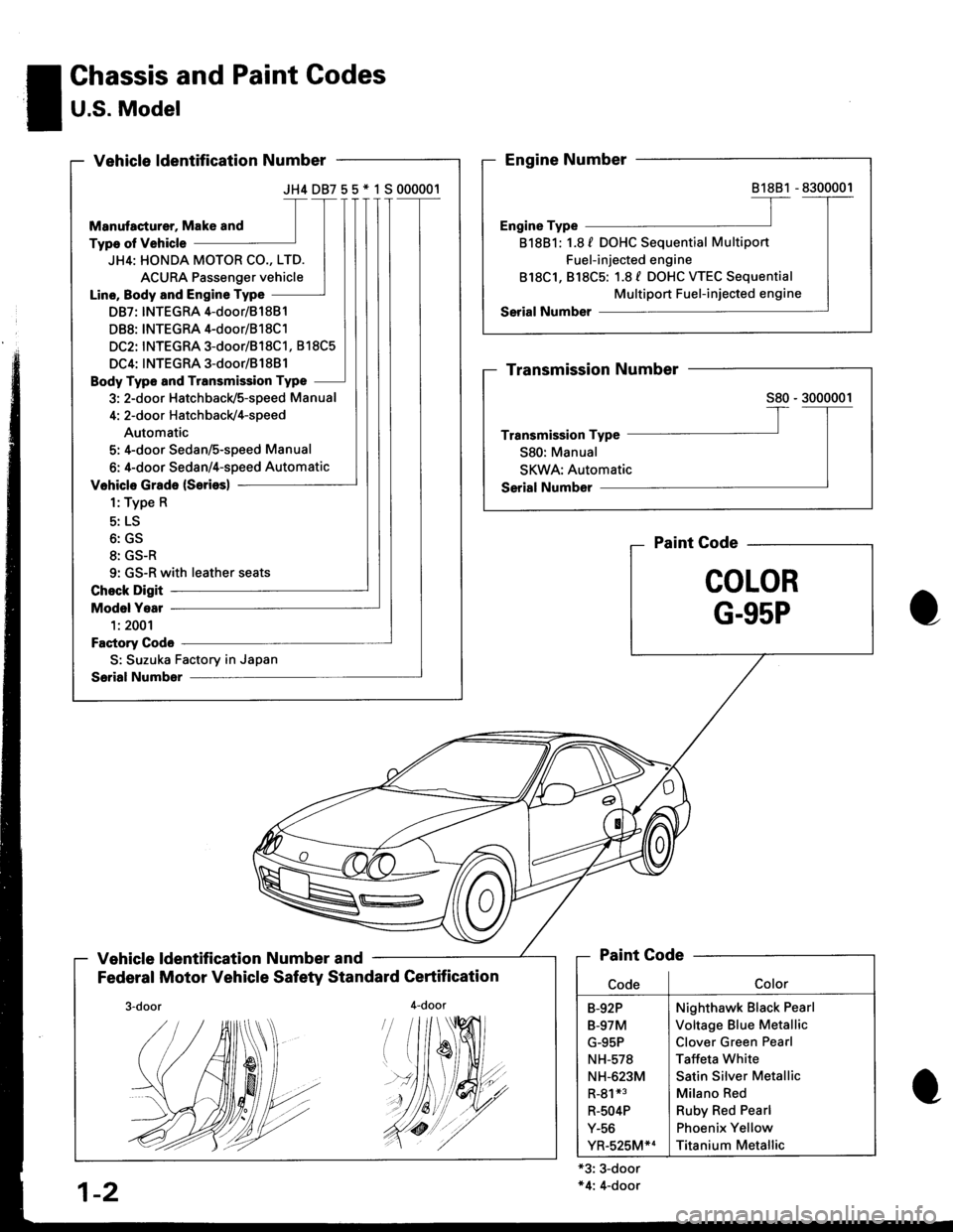
JH4DB755*1S000001
JH4: HONDA MOTOR CO., LTD.
ACURA Passenger vehicle
Line, Body and Engine Type
DB7: INTEGRA 4-door/81 881
DB8: INTEGRA 4-door/B1 8C1
DC2: INTEGRA 3-door/818C1, 818C5
DC4: INTEGRA 3-door/B1881
Body Type and Transmission Type
3: 2-door Hatchback/5-speed Manual
4: 2-door Hatch back/4-speed
Automatic
5: 4-door Sedan/S-speed Manual
6: 4-door Sedan/4-speed Automatic
9: GS-R with leather seats
S: Suzuka Factory in Japan
! Chassis and Paint Codes
I U.S. Model-
Vehicle ldentification Number and
Federal Motor Vehicle Safety Standard Certification
4-door
Paint Gode
COLOR
G-95P
'#19
'//dt
+3: 3-door*4: 4-door
81881
818B1: 1.8 f DOHC Sequential Multiport
Fuel-injected engine
818C1, 818C5: 1.8 f DOHC WEC Sequential
Multiport Fuel-injected engine
Paint Code
Nighthawk Black Pearl
Voltage Blue Metallic
Clover Green Pearl
Taffeta White
Satin Silver Metallic
Milano Red
Ruby Red Pearl
Phoenix Yellow
Titanium Metallic
B-92P
B-97M
G-95P
NH-578
NH-623M
R-81*3
R-504P
Y-56
YR-525M*4
1-2
./.4r//.'.
Page 1639 of 1681
JH4DC238* 1 S800001
JH4: HONDA MOTOR CO., LTD.
ACURA Passenger car
Line, Body and Engine Type
DC2: INTEGRA 3-door/818C1, 818C5
DC4: INTEGRA 3-door/81 88l
Body Type and Transmission Type
3: 2-door Hatchbacld5-speed Manual
S: Suzuka Factory in Japan
\
Canada Model
Vehicle ldentification Number and
Canadian Motor Vehicle Safety Standard Gertification
Paint Gode
COLOR
NH.O
81881
818B1: 1.8 f DOHC Sequential Multiport
Fuel-injected engine
818C1, 818C5: 1.8 / DOHC WEC Sequential
Multiport Fuel-injected engine
Nighthawk Black Pearl
Championship White
Satin Silver Metallic
Milano Red
Titanium Metallic
rfilill
1-3
Page 1649 of 1681
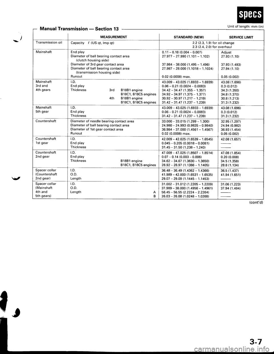
Unit of length: mm (in)Manual TransmissionSection 13
_/
/
MEASUREMENTSTANDARD (NEW}SEBVICE LIMIT
Transmission oilCapacity / (US qt, lmp qt)2.2 12.3, 1.9) for oil change2.3 12.4,2.0) for overhaul
MainshaftEnd playDiameter of ball bearing contact area(clutch housing side)Diameter of 3rd gear contact areaDiameter of ball bearing contact area(transmission housing side)Runout
0.1 1 - 0.18 (0.004 - 0.007)27 .977 - 27.990 (1 .101 - 1.102]|
37.984 - 38.000 (1.495 - 1.496)27.987 - 28.000 (1.1018 - 1.1024l.
0.02 (0.0008) max.
Adiust27 .93 (1.101
37.93 (1 .493)27 .94 11.101
0.05 (0.002)
Mainshaft3rd and4th gears
LD.End playThickness 3rd 81881 engine818C1, B18C5 engines4th 81881 engine818C1, 818C5 engines
43.009 - 43.025 (1 .6933 - 1 .(0.06 - 0.21 (0.0024 - 0.0083)34.42 - 34.47 (1 .355 - 1.357)34.92 - 34.97 (1.37 5 -'�t.377 )30.92 - 30.97 (1.2't7 -'�t.219)
31.42 - 31.47 n.237 - 1.239)
i939)43.0t0.3 ((
34.334.830.831 .3
(1.696)
.01211.350)1.370)1.21311.2321
Mainshaftsth geart.D.End playTh ickness
43.009 - 43.025 (1.6933 - 1.6939)0.06 - 0.21 (0.0024 - 0.0083)31 .42 - 31 .47 11 .237 - 1.2391
43.08 (1.696)
0.3 (0.012)
31.3 11.2321
CountershaftDiameter of needle bearing contact areaDiameter of ball bearing contact areaDiameter of 1st gear contact areaRunout
33.000 - 33.015 (1 .299 - 1 .300)24.980 - 24.993 (0.9835 - 0.9840)36.984 - 37.000 (1.4561 - 1.456710.02 (0.0008) max.
32.95 (1.2971
24.94 (0.982)
36.93 (1 .454)0.05 (0.002)
Countershaft1 st geart.D.End playTh ickness
42.009 - 42.025 (1.6539 - 1.6545)0.045 - 0.205 (0.0018 - 0.0081)31.45 - 31 .50 (1.238 - 1.240)
42.08 (1.657)
Countershaft2nd geart.D.End playThickness 81881 engine818C1, 818C5 engines
47.009 - 47 .025 (1.8507 - 1.8514)0.07 - 0.14 (0.003 - 0.006)34.62 - 34.67 (1 .3630 - 1.3650)28.92 - 28.97 (1.1386 - 1.1405)
47.08 (1 .8s410.20 (0.008)
34.5 (1.358)
28.8 (1.1341
Spacer collar(Countershafl
2nd gear)
t.D.o.D.Length
36.48 - 36.49 (1.4362 - 1.4366)41.989 - 42.000 (1.6531 - 1.6535)29.07 -29.09 (1.1445- 1.14531
36.5 (1 .437)41.94 (1.651)
Spacer collar(Mainshaft
4th and5th gears)
t.D.o.D.Length AB
31 .002 - 31 .012 11 .2205 - 't .2209'37.989 - 38.000 ( 1.4956 - 1.4961 )56.45 - 56.55 (2.2224 - 2.2264'�)26.03 - 26.08 (1.0248 - 1.0268)
31.06 (1 .223)37.94 (1 .494)
(cont'd)