Page 1129 of 1681

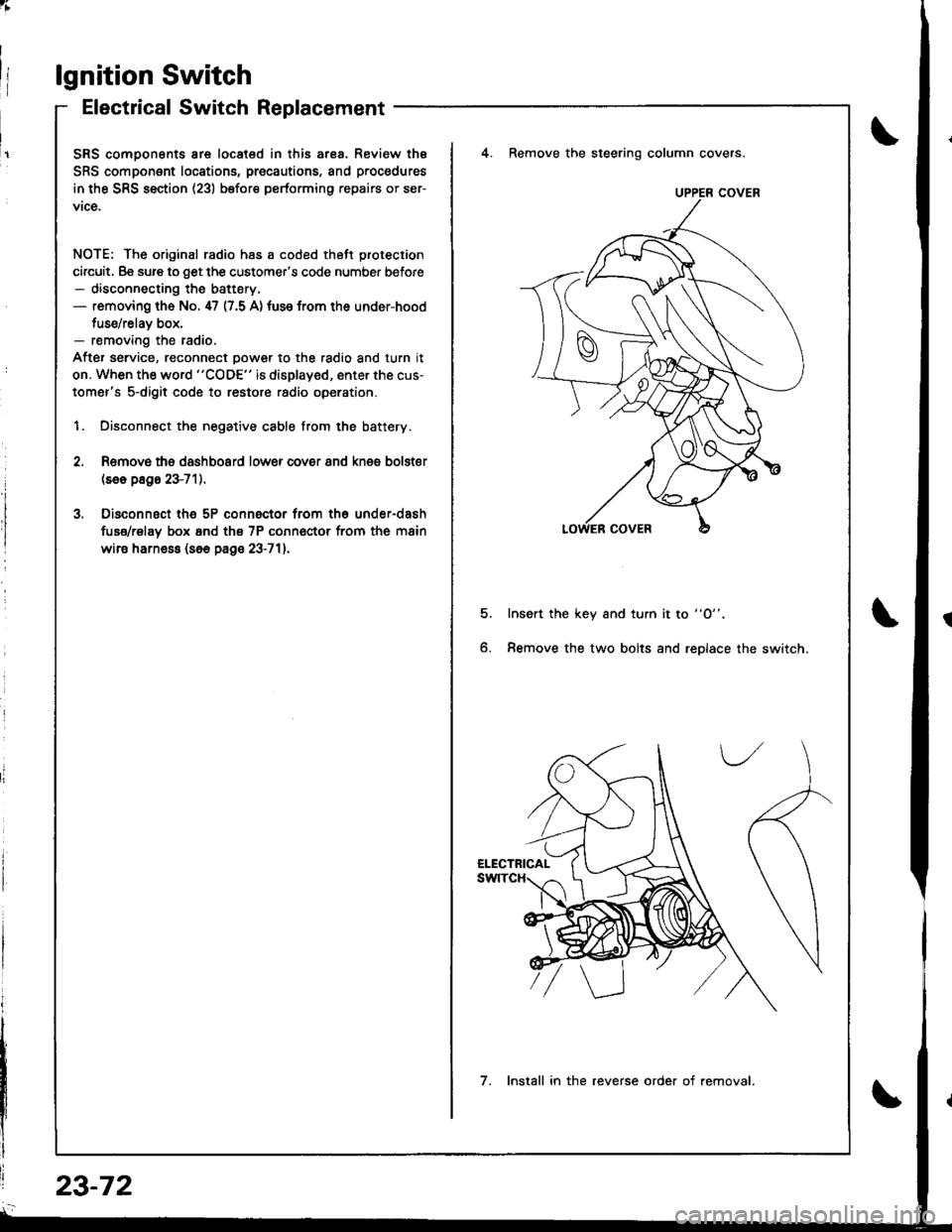
lgnition Switch
Electrical Switch Replacement
SRS comoonents are located in this ar8a. Review thE
SRS component locations, precautions, and procedures
in the SRS section (23) before performing repairs or ser-
vice.
NOTE: The original radio has a coded thett protection
circuit, Be sure to get the customer's code number before- disconnecting the battery.- removing th6 No. 47 (7.5 A) tuse from the under-hood
tuse/relav box,- removing the radio.
After service, reconnect oower to the radio and turn it
on. When the word "CODE" is displayed, enter the cus-
tomer's s-digit code to restore radio operation.
1. Disconnect the negative cable from the battery.
4. Remove the steering column covers.
Romovs ths dashboard lower cover 8nd knes bolster(se6 p8g6 23-71).
Disconnsct th6 5P connector from th6 under-dash
fuse/rel8y box 6nd th€ 7P conn€ctor from the main
wire harne$ (s6e page 23-711.
5.Insert the key and turn it to "O".
Remove the two bolts and replace the switch6.
UPPER COVER
7. Install in the reverse order of removal.
23-72
Page 1130 of 1681

;
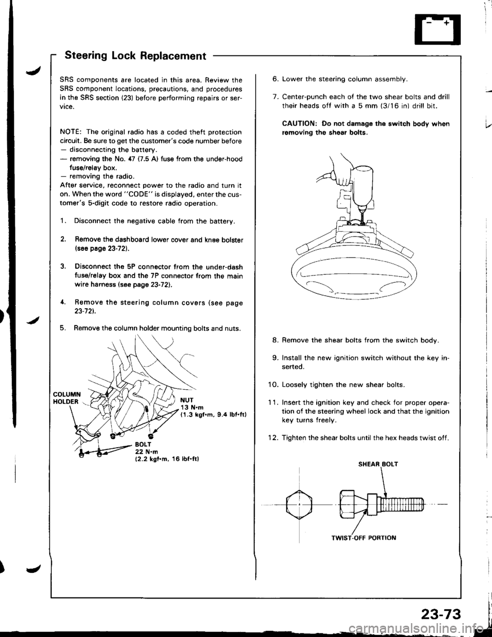
Steering Lock Replacement
SRS components are located in this area. Review the
SRS component locations, precautions, and procedures
in the SRS section (23) before performing repairs or ser-
vice.
NOTE: The original radio has a coded theft protection
circuit. Be sure to get the customer's code number before- disconnecting the battery.- removing the No. 47 (7.5 A) fuse trom the under-hood
fuse/relav box.- removing the radio.
After service, reconnect power to the radio and turn it
on. When the word "CODE" is displayed. enter the cus-
tomer's 5-digit code to restore radio operation.
1. Disconnect the negative cable from the battery.
2. Remove ths dsshboard lower cover and knee bolster(s6o p8ge 23-72).
3, Disconnect the 5P connector from the under-dash
fuse/relay box and the 7P connsctor from th€ main
wire harness (see page 23-72l.,
4. Remove the steering column covars (see page
23-721.
5. Remove the column holder mounting bolts and nuts.
NUT13 N.m(1.3 kgl.m, 9.4 lbt.ftl
BOLT22 N.m(2.2 kgf.m, 16 lbf.ftl
6.
7.
Lower the stee.ing column assembly.
Center-ounch each of the two shear bolts and drill
their heads oft with a 5 mm {3/16 in) drill bit.
CAUTION: Do not damage the switch body when
lemoving th€ sheal bolts.
Remove the shear bolts from the switch body.
Install the new ignition switch without the key in-
serted.
1O. Loosely tighten the new shear bolts.
11. Ins€rt the ignition key and check for proper opera-
tion of the sleering wheel lock and that the ignition
key turns freely.
12. Tighten the shear bolts until the hex heads twist off.
8.
Page 1156 of 1681
)
)
Charging System
Component Locationlndex
CHARGING SYSTEM LIGHT(ln the gauge assembly)Test, pages 23-102,103Bulb Locations, page 23-122
UNDER-HOOD FUSE/RELAY BOX(USA: HAS bUiIt-iN ELECTRICALLOAD DETECTOR (ELD) UNIT}Troubleshooting of ELD, secrion 11
BATTERYTest,
ALTERNATOR BELTInsp€ction and Adiustment, page 23_115ALTERNATORTroubleshooting, page 23'102Alternator/FegulatorTosl, pages 23-105,'106Replacement, page 107Overhaul, page 23-108
23-99
.t-
Page 1173 of 1681
Fan Controls
RADIATORFANswtTcHTest, page 23-119
Component Location Index
For the A/C system, see section 22.
UNDER-HOODFUSE/RELAY BOX
CONDENSER FAN RELAYTest, page 23-69
RADIATOR FAN RELAYTest, page 23,69
FAN MOTORTest, page 23-119
TOR FAN MOTORTest, page 23,119
: lt tt tt tt l
c=, Ll L-t t lf l]-]l
f1 a l f -r a'r -
I i I r""""rlla-t fr -
a tL) | |Irt -
1/^ l/-\ltr.z{ N/ L
Page 1251 of 1681

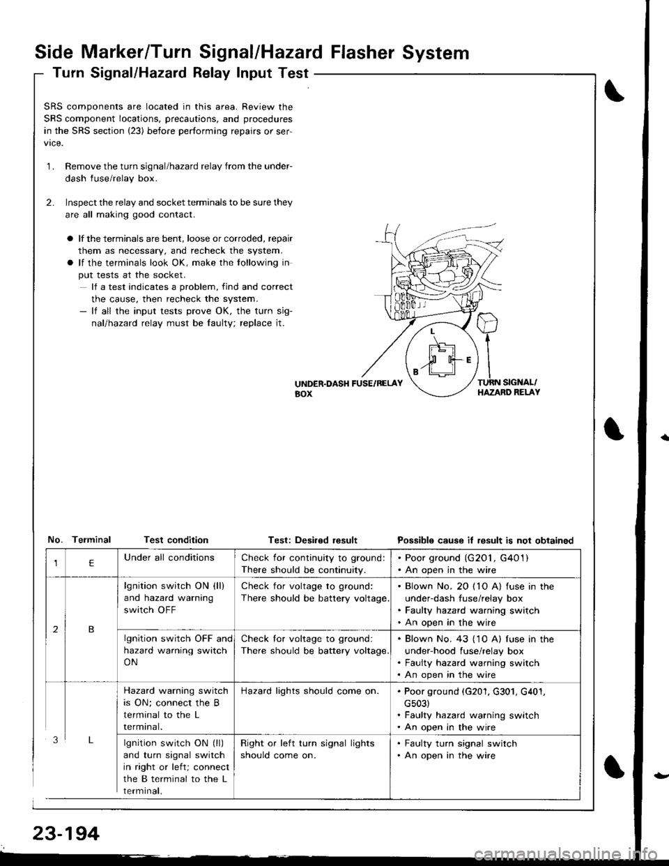
Side Marker/Turn Signal/Hazard Flasher System
Turn Signal/Hazatd Relay Input Test
\
t
SRS components are located in this area. Review the
SRS component locations, precautions, and procedures
in the SRS section (23) before performing repairs or ser-
1.Remove the turn signal/hazard relay from the under-
dash fuse/relay box.
Inspect the relay and socket terminals to be sure they
are all making good contact.
a lf the terminals are bent, loose or corroded, repair
them as necessary, and recheck the system.
a lf the terminals look OK, make the tollowing in
put tests at the socket.
lf a test indicates a problem, find and correct
the cause, then recheck the system.- lf all the input tests prove OK, the turn sig-
nallhazad relay must be faulty; replace jt.
2.
UiTDER.DASH FUSE/RELAYaox
TURN SIGNAL/HAZAND RELAY
No. Telminal Test conditionTest: Deaired resultPossible cause it result is not obtained
lgnition switch ON (ll)
and turn signal switch
in right or left; connect
the B terminal to the L
rermtnat,
Check for continuity to ground:
There should be continuity.
. Poor ground (G201, G401). An open in the wire
lgnition switch ON (ll)
and hazard warning
switch OFF
Check for voltage to ground:
There should be battery voltage
. Blown No. 20 ( 10 A) fuse in the
under-dash fuse/relay box. Faulty hazard warning switch. An open in the wire
lgnition switch OFF and
hazard warning switch
ON
Check lor voltage to ground:
There should be battery voltage.
. Blown No. 43 ('1 0 A) f use in the
under-hood fuse/relay box. Faulty hazard warning switch. An open in the wire
Hazard warning switch
is ON; connect the B
terminal to the L
rermtnat.
Hazard lights should come on.. Poor ground (G201, G301, G401,
cs03). Faulty hazard warning switch. An open in the wire
Right or left turn signal lights
should come on.
. Faulty turn signal switch. An open in the wire
Page 1253 of 1681
Stereo Sound System
Component Location Index
DOORSPEAKERReplacement, page 23-2OO
NOTE: The original radio has a coded theft protection
circuit. Be sure to get the customer's code number betore- disconnecting the battery.- removing the No.47 (7.5 A) fuse from the under-
hood fuse/relay box.- removing the radio.
After service, reconnect power to the radio and turn it
on. When the word "CODE" is displayed, enter the cus-
tomer's 5 digit code to restore radio operation.
STEREO RADIO/CASSETTEPLAYERRemoval, page 23-199Terminals, page 23 200
RIGHT TWEETERReplacement, page 23'200
BIGHT REARSPEAKERReplacement, page 23-201
LEFT REARSPEAKERReplacement, page 23,201POWER ANTENNA MOTORTest, page 23-202Replacernent, page 23-203
23-196
Page 1264 of 1681
Horn
Component Location lndex
JSRS components are located in this area. Review the
SRS component locations, precautions, and procedures
in the SRS section {23) before performing repairs or ser-
vtce,
HORNTest, page 23 211
HORN SWITCHESTest, page 23-209
CABLE REELReplacement, page 23 322UNDER-DASHFUSE/BELAY BOX
{---=-\s":=',-i=
il
-rrj _LJLi lJJJ I -.r ----------;- - t--t -----,------- L I t---HORN RELAY
I Wire colo6: WHT/GRN, WHT/GRN ILBLU/GRN, and BLU/REO ITest, page 23-70
)
23-207
Page 1266 of 1681

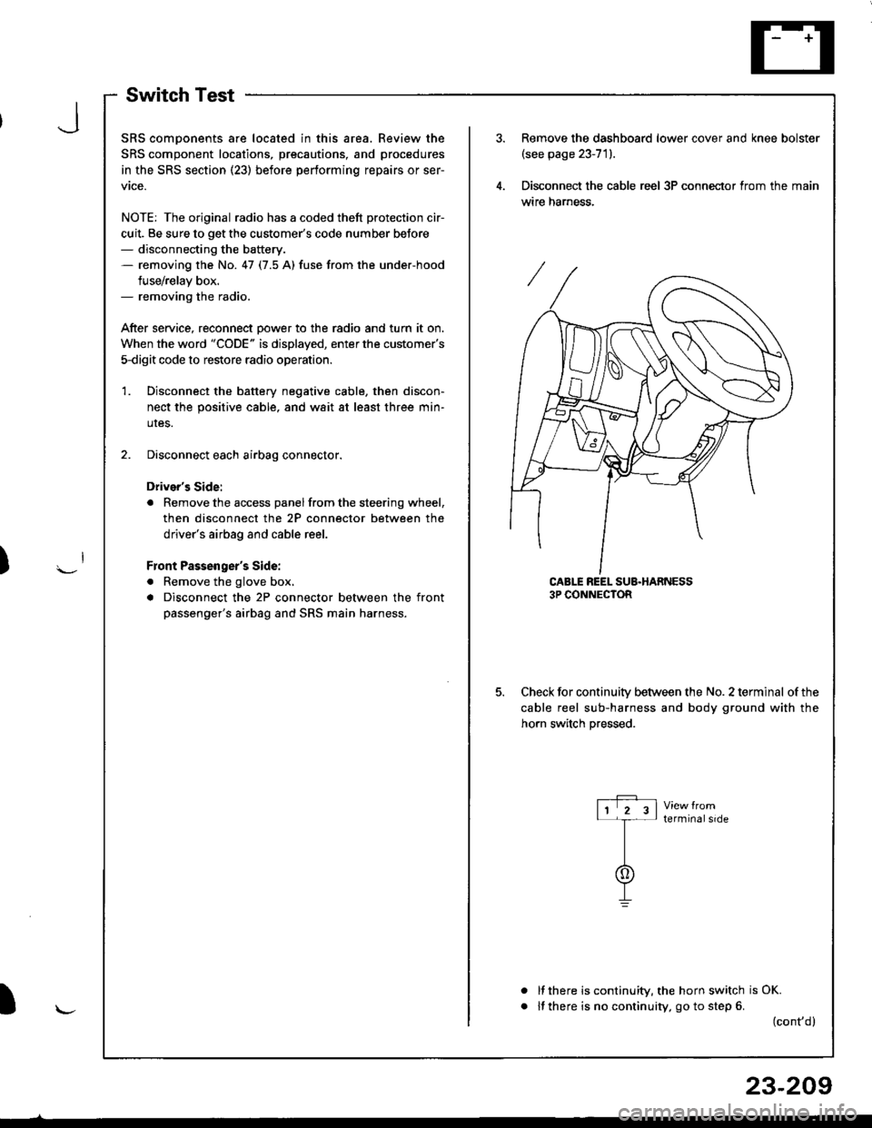
SwitchTest
SRS comDonents are located in this area. Review the
SRS component locations, precautions, and procedures
in the SRS section (23) before performing repairs or ser-
vtce.
NOTE: The original radio has a coded thett protection cir-
cuit. Be sure to get the customer's code number beJore- disconnecting the battery.- removing the No. 47 (7.5 A) fuse from the under-hood
fuse/relay box.- removing the radio.
After service, reconnect Dower to the radio and turn it on.
When the word "CODE" is displayed, enter the customer's
5-digit code to restore radio operation
Disconnect the battery negative cable, then discon-
nect the positive cable, and wait at least three min-
uIes.
Disconnect each airbag connector.
Driver's Side:
a Remove the access panel from the steering wheel,
then disconnect the 2P connector between the
driver's airbag and cable reel.
Front Passenger's Side:
. Remove the glove box,
a Disconnect the 2P connector between the front
passenger's airbag and SRS main harness.
1.
Remove the dashboard lower cover and knee bolster(see page 23-71).
Disconnect the cable reel 3P conneclor from the main
wtre narness.
CABLE REEL SUB.HARNESS3P CONNECTOR
Check for continuitv between the No. 2 terminal of the
cable reel sub-harness and body ground with the
horn switch Dressed.
terminalside
a
It there is continuity, the horn switch is OK.
lf there is no continuity, go to step 6. (cont,d)
r-P r11 2 3l-t-
I
I\-J
)
I
23-209