1998 HONDA INTEGRA air condition
[x] Cancel search: air conditionPage 418 of 1681

Automatic Transmission
Special Tools ................ '14-2
Descraption .................... 14-3
Clutches ............ ...... 14-6
Power Flow ..,........... 14-8
Electronic Control System ..................... 1 4-1 8
Hydraulic Control ...... 14-23
Hydraulic Flow .........- 14-28
Lock-up System ........ 14-38
Electrical System
Component Location -................................ 1 4-45
Circuit Diagram ............. 14-46
TCM Terminal Voltage/
Measuring Conditions ......,.................... 1 4-48
Troubleshooting Procedures .. . ... ........ ...... ... 14-50
Symptom-to-Component Chart
Electrical System ...... 14-54
Electrical Troubleshooting
Troubleshooting Flowcharts .......... ... ...,.. 14-56
Lock-up Control Solenoid Valve A/B Assembly
Test .................. ...... 14-A7
Replacement ............. 14-a7
Shilt Control Solenoid Valve A/B Assembly
Test .................. ...... '14-88
Replacement .,..,........ 14-88
lvlainshaf t/Countershaft Speed Sensors
Replacement ....-......,. 14-89
Transmission Control Module (TCM)
Replacement ............. 14-89
Hydraulic System
Symptom-to-Component Chart
Hydraulic System ...... 14-90
Road Test ,................... 14-94
Stall Speed
Test .................. ...... 14-97
Fluid Level
Checking/Changing .... 14-98
Pressure Testing ........... 14-99
Transmission
Transmission
Removal ............. ...... 14-10�4
lllustrated lndex
Transmission/Right Side Cover ............... 1 4-1 08
Transmission Housin9 ................,..,....... 1 4-1'1 O
Torque Converter Housing/ValveBody .................. .. 14-112
Right Side Cover
Removal ............. ...... 14-114
Transmission Housing
Removal ............. ...... 14-1 l6
Torque Converter Housing/Valve Body
Removal ............. ...... l4-1 18
Valve Caps
Description ...........-... 14-120
Valve Body
Repair ................ ...... 14-12'l
Valve
Assembly
ATF Pump
Inspeclton
Main Valve Body
Disassembly/lnspection/Reassembly
Regulator Valve Body
Disassembly/lnspection/Reassembly
Lock-up Valve Body
Disassembly/lnspection/Reassembly
Secondary Valve Body
Disassembly/lnspection/Reassembly
Servo Body
....... 14-124
....... 14-126
....... 14-127
....... 14 124
Disassembly/lnspection/Reassembly .......
1st-hold Accumulator/Right Side Cover
Disassembly/lnspection/Reassembly .......
Mainsha{t
14-130
14-132
Disassembly/lnspection/Reassembly ....... 14-133
Inspection ................. 14-134
Countershaft
Disassembly/lnspection/Reassembly,..,.., l4-136
Disassembly/Reassembly ..,...,..,.........,,.. 1 4-1 37
Inspection ......,...,..,... 14-138
One-way Clutch
Disassembly/lnspection/Reassembly ....,.. 14-141
Sub-shaft
Disassembly/lnspection/Reassembly ...,,..'14-142
Disassembly/Reassembly ....................... 1 4- l 43
Sub-shaft Bearings
Replacement ,..,,.,,..,.. 14-144
Clutch
lllustrated Index ................................... I 4-1 45
Disassembly ............. 14-144
Reassembly .............. 14-150
Torque Converter Housing Bearings
Mainshaft Bearing/Oil Seal
Replacement ......... 14-154
Countershaft Bearing Replacement ......... 1 4- 1 55
Transmission Housing Bearings
Mainshaft/Countershaft BearingReplacement ......,.. 14-'156
Sub-shaft Bearing Replacement .,............ 1 4-1 57
Reverse ldler Gear
Installation .........-..... 14-158
Parking Brake Stop
Inspection/Adjustment .......................... 1 4-1 58
Transmission
Reassembly .............. 14-160
Torque Converler/Drive Plate ..............,.,,.,, 1 4-1 67
Transmission
Installation ............... 14-168
Cooler Flushing ......... 14-172
ATF Cooler Hoses
Connection ,..,,,....,,.,, '14-'174
*shift cable
Removal/lnstallation . . .. .... ... .... ... .... .. . ... .. 14-'l75
Adjustment ,..,...,,,,.,, 14-'116*Shilt lever
Disassembly/Reassembly ....................... 1 4-'17 7'Shift Indicator Panel
Adjustment .............. 14-178
\l
)g
Page 466 of 1681

Terminal NumberSignalDescriptionMaasuring Conditlons/Tarminal Voliage
424ACCLAir conditioning (Ay'C) clutch relay
control
With A,/C comDressor ON: 0 V
With Ay'C compressor OFF: Battery voltage
A25tG1Power supply systemWith ignition switch ON (ll)r 12 V
426LG1Ground
B1Not used
82BAROS SBarometric pressure sensor signal
input
With ignition switch ON (ll) and depending on
barometric pressure: Approx. 3 V
B3ECTEngine coolant temperature sen-
sor signal input
With ignition switch ON (ll) and depending on
engine coolant tem perature: Approx. 0.1 - 4.8 V
B4TPSThrottle position sensor signal
input
With ignition switch ON (ll) 8nd throttle fully
open: 4.14 - 4.82 V
With ignition switch ON (ll) and throttle fully
closed: 0.44 - 0.56 V
B5VSSVehicle speed sensor signal inputWith ignition switch ON (ll) and front wheels
rotating; Pulsing signal
B6AFSBUpshifvdownshift comparative
signal output
With engine idling: 0 V
At uDshift or downshift: 5 V for an instant
B7AFSAUpshifvdownshift com parative
srgnal output
With engine idling: 0 V
At upshift or downshift: 5 V for an instant
B8NCSGCountershaft speed sensor signal
ground
Always: 0 V
B9NCCountershaft speed sensor signal
Input
Depending on vehicle speed: Pulsing signal
When vehicle is stopped:0 V
B10NMMainshaft speed sensor signal
input
Depending on vehicle speed: Pulsing signal
When vehicle is stoDoed: 0 V
811Not used
812STOP SWBrake switch signal inputWith ignition switch ON {ll) and b.ake pedal
depressed: Battery voltage
With ignition switch ON (lll and brake pedal
released:0 V
813Not used
814scsTiming adjustment
service check signal
With ignition switch ON (ll) and service check
connector oDen:5 V
With ignition switch ON (ll) and service check
connector connected with special tool: 0 V
815Not used
816Not used
817NMSGMainshaft speed sensor signalgroundAlways: 0 V
818Not used
819FASShift acknowledge inputWith engine idling: 5 V
At upshift or downshift: 0 V for an instant
820VBEF+5 V referenceWith ignition switch ON {lll: Approx. 5 V
82'lNot used
Not used
14-49
Page 536 of 1681

I
l"
I
J
NOTE:
a Clean all parts thoroughly in solvent or carburetor
cleaner and dry with compressed air.
a Blow out all passages.
a When removing the valve body replace the lollowing:. O-rings. Lock washers
1 . Remove the ATF feed pipes from the servo body, ser-vo detent base, accumulator cover, lock-up valve
body and main valve body.
2. Remove the three bolts securing the ATF strainer
and servo detent base, then remove the strainer
and detent base.
3. Remove the three bolts securing the accumulator
cover, then remove the accumulator cover.
4. Remove the six bolts securing the servo body. then
remove the servo body and separator plate.
5. Remove the one bolt securing the secondary valvebody, then remove lhe secondary valve body andseparator plate.
6. Remove the eight bolts securing the lubricator plate
and lock-up valve body, then remov€ th€ lubricator
plate. Iock-up valve body, and separator plate.
7. Remove the one bolt securing the regulator valve
body, then remove the regulator valve body.
8. Remove the stator shaft and stop shaft.
9. Remove the detent spring from the detent arm, then
remove the control shaft from the torque converter
housrng.
1O. Remove the detent arm and detent arm shatt from
the main valve body.
1 'l . Remove the four bolts securing the main valve body,
then remove the main valve body.
'I2. Remove the ATF pump driven gear shatt, then re-
move the ATF pump gears.
13. Remove the main separator plate with two dowel
pins.
15.
14. Clean the inlet opening ot the ATF st,ainer thorough-
ly with compressed air, then check that it is in good
condition. and the inlet opening is not clogged.
INLET OPENING
Replace the ATF strainer if it is clogged or damaged.
NOTE: The ATF strainer can be reused if it is notclogged.
14-119
Page 671 of 1681

Inspection and Adjustment
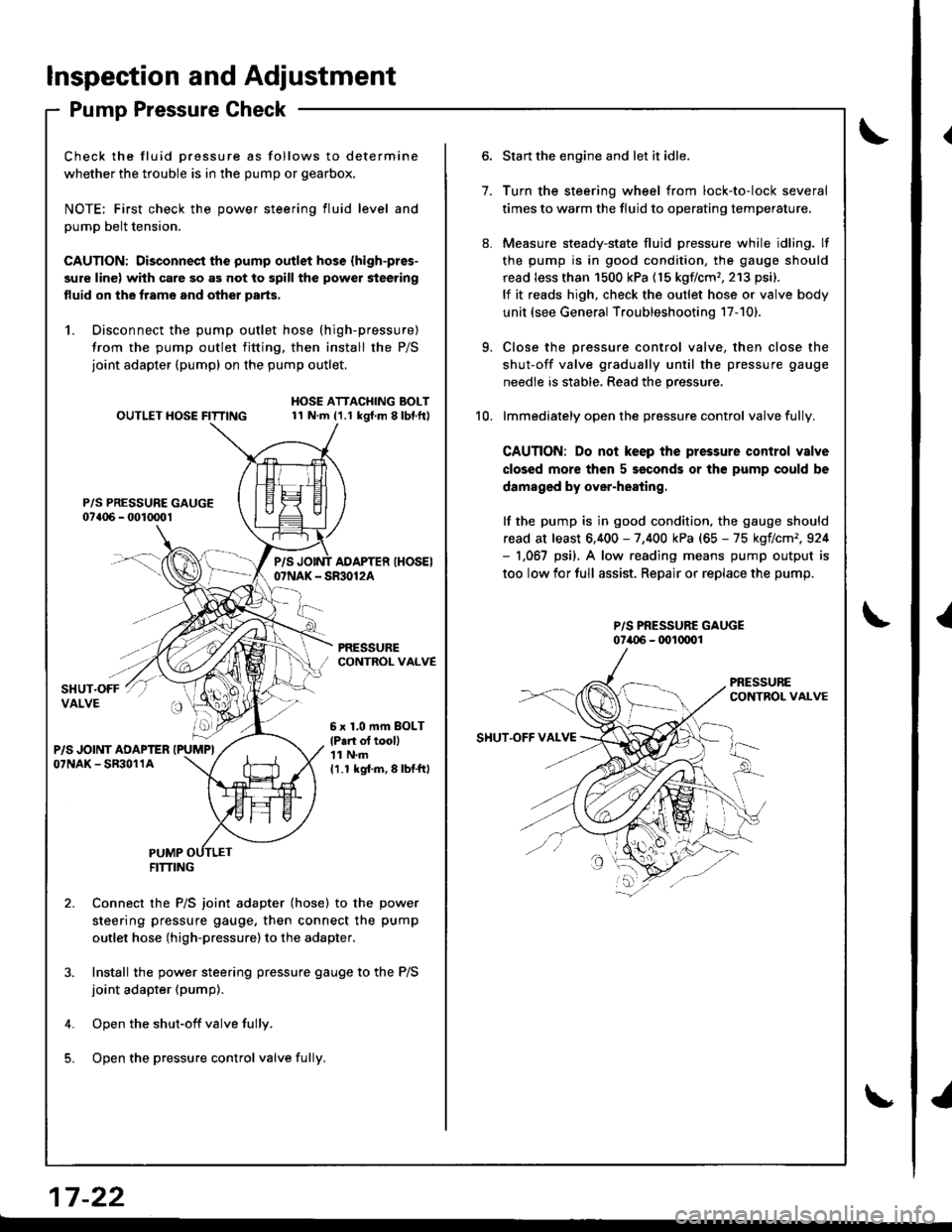
Pump Pressure Check
Check the fluid Dressure as follows to determine
whether the trouble is in the pump or gearbox.
NOTE; First check the power steering fluid level and
pump belt tension.
CAUTION: Disconnect the pump outlet hose (high-pres-
sure line) with care so as not to spill the power steering
fluid on the frame and other parts,
1. Disconnect the pump outlet hose (high-pressure)
from the pump outlet fitting, then install the P/S
joint adapter (pump) on the pump outlet.
P/S PRESSURE GAUGE07a06 - 001mo1
OUTLET HOSE FITTINGHOSE ATTACHING BOLT11 N.m (1.1 kgt.m 8lbl.ft)
PRESSURECONTROL VALVE
P/SAOAPTER IHOSEI07NAK - SR30124
6 x 1,0 mm BOLT
lP.n ol tooll'| 1 N.m
11.1 kgi.m,8lbtftl
PUMPFITTING
Connect the P/S joint adapter (hose) to the power
steering pressure gauge, then connect the pump
outlet hose (high-pressure)to the adapter.
Install the power steering pressure gauge to the P/S
joint adapter (pump).
Open the shut-off valve fully.
Open the pressure control valve fulli.
1.
Start the engine and let it idle.
Turn the steering wheel from lock-to-lock several
times to warm the fluid to operating temperature.
Measure steady-state fluid pressure while idling. lf
the pump is in good condition, the gauge should
read less than 1500 kPa (15 kgflcm'�,213 psi).
lf it reads high, check the outlet hose or valve body
unit (see General Troubleshooting 17-101.
Close the pressure control valve, then close the
shut-off valve gradually until the pressure gauge
needle is stable, Read the pressure.
lmmediately open the pressure control valve fully.
CAUTION: Do not keep the pressure control valve
closed more then 5 seconds or the pump could be
damaged by over-heating.
lf the pump is in good condition, the gauge should
read at least 6,400 - 7,400 kPa (65 - 75 kgflcm',924- 1,067 psi). A low.eading means pump output is
too low for full assist. Repair or replace the pump.
P/S PRESSURE GAUGE07i.{)6 - (x)l(xrol
9.
10.
SHUT.OFF VAI.VE
17 -22
{
I
Page 788 of 1681

Troubleshooting Precautions
Kickback
L The motor operates when the ABS is functioning, and the fluid in the reservoir is forced out to the master cylinder,
causing kickback at the brake pedal.
Pump Motol
1. The pump motor operates when the ABS is functioning.
2. The ABS control unit checks the pump motor operation during initial diagnosis and when the vehicle is started. You
mav hear the motor operate at this time, but it is normal
Brake Fluid Replacement/Air Bleeding'1. Brake fluid replacement and air bleeding procedures are the same as vehicles without ABS. To ease bleeding, start
with the front wheels.
Troubleshooting
1. The troubleshooting flowcharts procedures assume that the cause of the problem is still present and the ABS indica-
tor is still on. Following the flowchart when the ABS indicator does not come on can result in incorrect diagnosis.
2. Ouestion the customer about the conditions when the problem occurred, and try to reproduce the same conditions
for troubleshooting.
Find out when the ABS indjcator came on. such as during initial diagnosis. during ABS control, after ABS control,
when vehicle speed was at a certain speed, etc.
3, When the ABS indicator does not come on during the test-drive, but troubleshooting is performed based on the DTC,
check for loose connectors, poor contact at the terminals, etc. before you start troubleshooting'
4. After troubleshooting, erase the DTC and test-drive the vehicle. Be sure the ABS indicator does not come on.
5. The connector illustrations show the female terminals with a single outline and the male terminals with a double outline.
Page 995 of 1681

SYMPTOMREMEDY
Hot air tlow is low.Blower motor runs, but one or more
speeds are inoperative.
Follow the flowchart (see page 21-9).
Blower runs propetly.Check for the following:. Clogged heater duct
. Clogged heater outlet
. Incorrect door Position
No hot air tlowBlower motor does not run at all.Follow the flowchart {see page 21-11}
Blower motor runs.Check for the following:
. clogged heater duct
. Clogged blower outlet. Clogged heatet valve
. Faultv air mix door
. Heater valve cable adjustment lsee page 21-27].
. Air mix control cable adiustment {see page 21-27)
. Faulty thermostat (see section 10)
. Clogged evsporator (with air conditioning)
. Frozen evaDorator (with air conditioning)
Mode control motor does not run, or one or more mooes are
inoDeratave.
Follow the flowchart (see page 21-14).
Recirculation control door does not change between FRESH
and RECIRCULATE.
Follow the flowchart {see page 21-17).
Troubleshooting
Symptom Chart
NOTE: Check the engin€ coolant level and allow the engine to warm up before troubleshooting'
21-8
v
Page 1007 of 1681

Blower Unit
Replacement
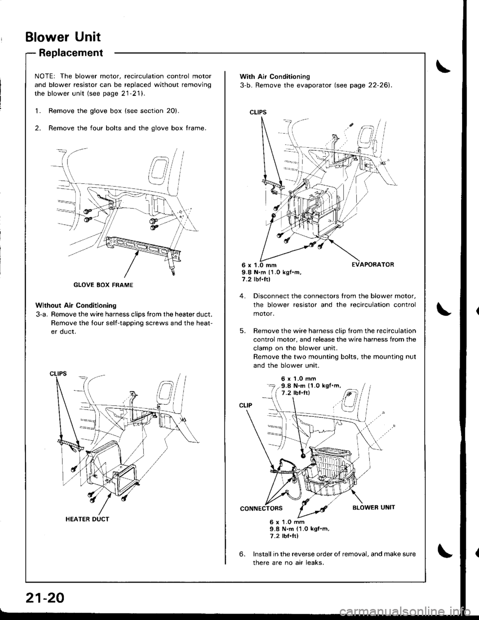
NOTEr The blower motor, recirculation control motor
and blower resistor can be replaced without removjng
the blower unit (see page 21-21).
Remove the glove box {see section 20}.
Remove the four bolts and the glove box frame.
Without Air Conditioning
3-a. Remove the wire harness clips trom the heater duct.
Remove the tour self-tapping screws and the heat-
er duct.
1.
2.
HEATER DUCT
21-20
With Air Conditioning
3-b. Remove the evaporator (see page 22-26).
CLIPS
9.8 N.m 11.0 kgf.m,7.2 rbf.ftl
4. Disconnect the connectors from the blower motor,
the blower resistor and the recirculation control
motor,
5. Remove the wire harness clip from the recirculation
control motor, and release the wire harness from the
clamp on the blower unit.
Remove the two mounting bolts, the mounting nut
and the blower unit.
6 x 1.0 mm
6.
6 x 1.O mm9.8 N.m (1.0 kgf'm,7.2 rbr.ftl
Install in the reverse order of removal. and make sure
there are no air leaks.
9.8 N.m (1.0 kgl'm,
Page 1021 of 1681

lllustrated Index
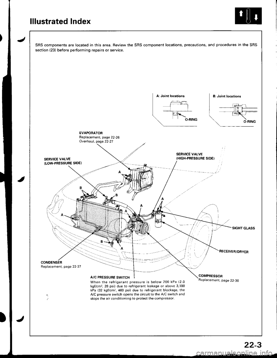
JSRS components are located in this area. Review the SRS component locations, precautions, and procedures in the SRS
section (23) before performing repairs or service.
EVAPORATORReplacement, page 22,26Ove.haul. page 22-27
SERVICE VAI-VE
ILOW.PRESSURE SIDE)
SERVICE VALVE{HIGH.PRESSUEE SIDE}
SIGHT GLASS
CONOENSERReplacement, page 22 37
A/C PRESSURE SWITCHCOMPRESSOR
When the refrigerant pressure is below 200 kPa (2.0
kgllcm,, 28 psi) due to refrigerant leakage or above 3,'100kPa (32 kgtcm,,460 psi) due to relrigerant blockage, theA,/C pressure sw;tch opens the circuit to the A,/C switch andstops the air conditioning to protect the compressor.
page 22-30
22-3