Page 1250 of 1681
Circuit Diagram
UNDEB HOOD FUSUBELAY 8OX
N0.41 (100A) No.5l (l5A)
UNDER DASHFUSE/FELAY BOXCOMEINATIONLIGHT SWITCH
wHT ---{. rcr- RED/GRNV rclrrtor swror
WHT/BLK +WNTBLK/YEL
WHT/GRN
I GFNBLU GRIVBLU
-]JJ
IVVGRNIELU TRATLERI L|GHTINGI CONNECTOR
TRUN SIGNALswrTcHF (Not used)
GBN/ORN
GRNioRN-
GRNALU GRN/BLU
RED
tltl
rl
I
t
OASH LIGHTSBFIGHTNESSCONTROLLEH
*f --.f ,-+r*n"+
RN/YE
t
TBLK
GRN,YEL
tttol
I RE,
lo'8LK
8LK
I
G201G401
GFN/BLU
)
23-193
Page 1251 of 1681

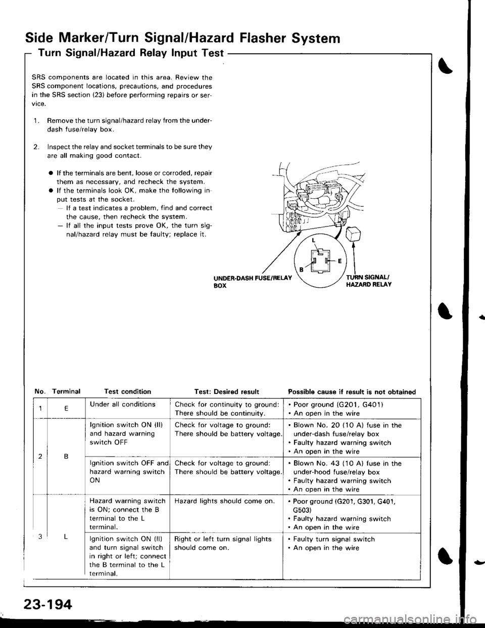
Side Marker/Turn Signal/Hazard Flasher System
Turn Signal/Hazatd Relay Input Test
\
t
SRS components are located in this area. Review the
SRS component locations, precautions, and procedures
in the SRS section (23) before performing repairs or ser-
1.Remove the turn signal/hazard relay from the under-
dash fuse/relay box.
Inspect the relay and socket terminals to be sure they
are all making good contact.
a lf the terminals are bent, loose or corroded, repair
them as necessary, and recheck the system.
a lf the terminals look OK, make the tollowing in
put tests at the socket.
lf a test indicates a problem, find and correct
the cause, then recheck the system.- lf all the input tests prove OK, the turn sig-
nallhazad relay must be faulty; replace jt.
2.
UiTDER.DASH FUSE/RELAYaox
TURN SIGNAL/HAZAND RELAY
No. Telminal Test conditionTest: Deaired resultPossible cause it result is not obtained
lgnition switch ON (ll)
and turn signal switch
in right or left; connect
the B terminal to the L
rermtnat,
Check for continuity to ground:
There should be continuity.
. Poor ground (G201, G401). An open in the wire
lgnition switch ON (ll)
and hazard warning
switch OFF
Check for voltage to ground:
There should be battery voltage
. Blown No. 20 ( 10 A) fuse in the
under-dash fuse/relay box. Faulty hazard warning switch. An open in the wire
lgnition switch OFF and
hazard warning switch
ON
Check lor voltage to ground:
There should be battery voltage.
. Blown No. 43 ('1 0 A) f use in the
under-hood fuse/relay box. Faulty hazard warning switch. An open in the wire
Hazard warning switch
is ON; connect the B
terminal to the L
rermtnat.
Hazard lights should come on.. Poor ground (G201, G301, G401,
cs03). Faulty hazard warning switch. An open in the wire
Right or left turn signal lights
should come on.
. Faulty turn signal switch. An open in the wire
Page 1256 of 1681
Unit Removal
NOTE: The original radio has a coded thelt protection
circuit. Be sure to get the customer's code number before- disconnecting the battery.- removing the No. 47 (7.5 A) fuse in the under-hood
fuse/relay box.- removing the radio.
After service. reconnect power to the radio and turn it on.
When the word "CODE" is displayed, enter the cus-
tomer's 5-digit code to restore radio operation.
'1. Remove the center console (see section 20).
2. Remove the cigarette lighter assembly (see page
23-2131.
)
FRONT CONSOLE
Remove the four mounting screws, then remove the
front console.
Loosen the two mounting screws. then disconnect
the 16P connector and the antenna lead, and Dull
out the stereo radio/cassette plaver.
16P CONNECTOR
ANTENNA SUB-LEAD
23-199
Page 1257 of 1681

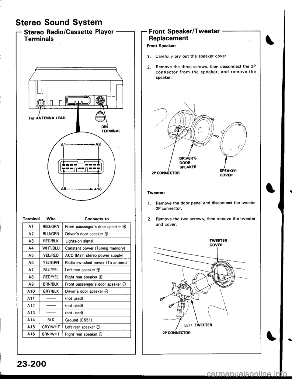
Stereo
Stereo
Sound System
Radio/Cassette PlayerFrontSpeaker/Tweeter
Replacement
Front Sp€aker:
'1. Carefully pry out the speaker cover.
2. Remove the three screws, then disconnect the 2P
connector from the speaker, and remove the
speaKer.
2P CONNECTOR
Tweoter:
1. Remove the door panel and disconn€ct the tweeter
2P connector.
2. Remove the two screws, then remove the tweeter
ano cover.
A
//1
\7
)-ISPEAKERCOVER
2P CONNECTOR
Terminals
T€rminalWireConnecta to
\
FoT ANTENNA LEAD
oIttFRMINAL
a9- -- -------> A 16
AIRED/GRNFront passenge.'s door speaker @
A2BLU/GRNDriver's door speaker O
A3RED/BLKLights-on signal
A4WHT/BtUConstant power (Tuning memory)
A5YEL/REDACC {Main stereo power supply)
A6YEL/GRNRadio switched power 1To antenna)
A7BLU/YELLeft rear speaker @
A8RED/YELRight rear speaker @
A9BRNi BLKFront passenger's door speaker O
A10GRY/BLKDriver's door speaker O
A11(not used)
{not used)
A13(not used)
A14 BLKGround {G551)
A15 GRY,ryVHTLeft rear speaker O
A168RN AVH TRight rear speaker O
23-200
Page 1263 of 1681
Clock
CircuitDiagram
CAUTION:
a Prv the clock out at the left side.
a Be careful not to damage the clock and the dashboard
when prying the clock out.
1. Pry the clock out from the dashboard. then discon-
nect the 4P connector.
4P CONNECTOR
CLOCK
BATTERY
UNDER,HOODFUSE/RELAYBOX
WI-]T/BLK
I
A/ BAT I 1GN TION
Y*"t No3o(7.sA)-|" -v
F'nrrn l
I
WHT/BLU
l- wHT 8LU
al-
STEREO BADIOiCASSETTE PLAYEF
BLK
G201G401
BLKGround
BYELrG1
pry,
(Main clock power sup-
cRE D/BLKLights-on signal
DWHT/BLUConstant power
(Time memory)
Terminals
23-206
Page 1267 of 1681
Horn
Switch Test (cont'd)
Remove the driver's airbag assembly (refer to the
SRS sub-section in section 23).
Check for continuity between the No. 2 terminal of
the cable reel sub-harness 3P connector and horn
Dositive terminal.
lf there is no continuity. replace the cable reel.
lf there is continuity, replace the horn switch.
a
a
HORN POSITIVE TERMINAL
23-210
9.
10.
11.
12.
lf all tests prove OK, reinstall the driver's airbag
assembly (re{er to the SRS sub-section in section 23).
Reconnect the driver's airbag connectors, and rein-
stall the access panel on the steering wheel.
Reconnect the front passenger's airbag connector,
and reinstall the glove box.
Connect the battery positive cable, then connect the
negative cable.
Atter installing the airbag assembly, confirm that
- the SRS indicator light should come on for about
six seconds and then go off with the ignition switch
oN 0t).- the horn sounds with the horn button pressed.
Page 1269 of 1681
Gigarette Lighter
Circuit Diagram
UNDER.HOOD FUSURELAY 8OX
3o{75A) J-
Y
Lit*is***/
I
r'
OASH LIGHTSERIGHTNESSCONTFOLLER
BLK
G201G401
23-212
Page 1270 of 1681
J
)
1.Remove the two ashtray mounting screws. Then pull
out the ashtray from the front console panel. and
disconnect the 4P connector.
2.Disconnect the thermofuse case from the
end.
Remove the thermal protector, and pull
cigarette lighter socket.
socket
out the
CIGARETTE LIGHTERLTGHT t1.4 Wl
ASHTRAY LIGHTt1.4 WlEULB CASE
FRONT CONSOLEPANEL
THERMOFUSECASE
RING NUT
THERMAL PROTECTOR
scREws
ILLUMINATIONRING
CrcANETTE LIGHTERsocxET
When installing the cigarette lighter, align each lug
on the face panel, illumination ring, and cigarette
lighter socket with the groove of the hole. then po-
sition the bulb housing on the thermal protector be-
tween the stops in the console panel.
Make sure that the ground wire, bulb socket, and
thermofuse housing are seated to the cigarette light-
er assembly.
5.
ASHTRAY
l\-
23-213